Table of Contents
Advertisement
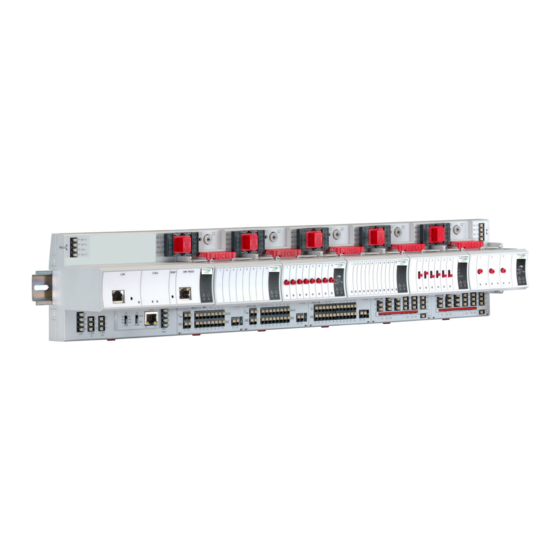
CentraLine I/O Modules
CONTENTS
Safety Information ............................................................... 2
General Safety Information ............................................. 2
Safety Information as per EN60730-1 ............................. 2
System Overview ................................................................ 3
System Architecture ........................................................ 3
CentraLine I/O Modules and Sockets ............................. 4
Interfaces and Bus Connections ..................................... 7
Technical Data ................................................................. 7
Planning ............................................................................... 8
Overview .......................................................................... 8
Transformer Selection ..................................................... 8
Fusing Specifications ...................................................... 9
System Protective Earth Grounding ................................ 9
Lightning Protection ......................................................... 9
Panel Bus Topologies ..................................................... 9
Bus Topologies ............................................. 9
Cable Specifications ........................................................ 9
Dimensions .................................................................... 11
Mounting/Dismounting Modules ..................................... 12
Mounting/Dismounting Modules / Sockets .................... 12
Mounting/Dismounting Electronic Modules ................... 14
Mounting/Dismounting Cross Connectors .................... 15
Mounting/Dismounting Swivel Label Holders ............... 15
Wiring and Setting up the System .................................. 16
General Safety Considerations ..................................... 16
Wiring Push-in Terminals .............................................. 16
Connecting Power Supply ............................................. 17
Connecting Single Bus Controller Systems .................. 17
Connecting Panel Bus and L
Controller Systems ........................................................ 18
Addressing Panel Bus I/O Modules .............................. 20
Connecting Field Devices ............................................. 20
Commissioning and Updating Firmware ....................... 21
Description of the CentraLine I/O Modules .................... 22
Common Features ......................................................... 22
Analog Input Modules .................................................... 22
Analog Output Modules ................................................. 27
Binary Input Modules ..................................................... 33
Relay Output Modules ................................................... 36
Copyright © 2019 Honeywell GmbH ● All Rights Reserved
W
Bus Mixed
ON
ORKS
Installation &
Commissioning
Instructions
INSTALLATION AND COMMISSIONING INSTRUCTIONS
Floating Output Module ................................................. 41
Mixed Panel Bus I/O Modules ....................................... 45
Description of Extra Parts ................................................ 49
XS814 Auxiliary Terminal Package ............................... 49
XS830 Auxiliary Terminal Package ............................... 49
XS831 Auxiliary Terminal Package ............................... 49
XS815 Cross Connectors .............................................. 50
XAL10 Swivel Label Holders ......................................... 50
XAL11 Swivel Label Holders ......................................... 50
XS816 Bridge Connectors ............................................. 50
LonWorks Software Interface Description ...................... 51
Overview ........................................................................ 51
CLIOL821A Analog Input Module .................................. 51
CLIOL(R)822A Analog Output Module .......................... 53
CLIOL823A Binary Input Module ................................... 54
CLIOL(R)824A Relay Output Module ............................ 55
Troubleshooting ................................................................ 56
Testing Wiring Connections ........................................... 56
CentraLine I/O Module Troubleshooting ....................... 56
Appendix: Sensor Characteristics ................................... 60
BALCO 500 .................................................................... 60
NTC 20 k ..................................................................... 61
PT 1000 .......................................................................... 62
NI1000TK5000 ............................................................... 64
NTC 10 kΩ ..................................................................... 65
PT 3000 .......................................................................... 66
Johnson A99 PTC Thermistor ....................................... 67
Trademark Information
Echelon, LON, L
M
ON
trademarks of Echelon Corporation registered in the United
States and other countries.
3.4
CentraLine
I/O MODULES
, L
T
, L
W
, Neuron, are
ARK
ON
ALK
ON
ORKS
EN1Z-0973GE51 R0119
Advertisement
Table of Contents


Need help?
Do you have a question about the CLIOP821A and is the answer not in the manual?
Questions and answers