
Related Manuals for SPR Therapeutics, Inc. SPRINT PNS System

Summary of Contents for SPR Therapeutics, Inc. SPRINT PNS System
- Page 1 Clinician Instructions for Use 1 | SPRINT ® PNS System – Clinician Instruction for Use [L0090-MAN-000 Rev F]...
- Page 2 © 2018 SPR Therapeutics, Inc. All rights reserved. 2018-5-XX Kommentar [MW1]: Will require to be updated prior to final release SPR Therapeutics, SPRINT ® , MicroLead™ and OnePass Introducer™ are trademarks of SPR Therapeutics, Inc., registered in the U.S. and other countries. The BLUETOOTH ®...
-
Page 3: Table Of Contents
Table of Contents Glossary.............................5 1 Introduction ............................6 1.1) Indications for Use ..........................7 1.2) Contraindications ..........................7 1.3) Warnings ............................7 1.4) Precautions ............................9 1.5) MRI Safety Information ........................11 2 System Overview .......................... 13 2.1) System Components ........................13 2.2) Programming Tools Overview ...................... -
Page 4: Glossary
Chapter 1: Introduction Glossary Amplitude – the level of current flowing during the stimulus pulse. The Amplitude is measured in milliamperes (mA). See Figure G.1 G.1: Stimulus waveform; Two stimulus pulses are shown Burst – the portion of a stimulation cycle during which stimulus pulses are delivered at the maximum programmed amplitude and pulse duration (Figure G.2). - Page 5 Chapter 1: Introduction Gap – the portion of a stimulation cycle during which stimulus pulses are not delivered (Figure G.2). (Not applicable when duty cycle is set to 100%; i.e., when the pulse train continues at set value until stimulation is stopped.) Intensity - the strength of the stimulation delivered on a scale of 1.0 (minimum) to 100.0 (maximum).
-
Page 6: Introduction
Patient Instructions for Use (Section 2: Important Safeguards). SPRINT PNS System placement The Sprint PNS System is for use in the back and/or extremities. The Sprint PNS System is not intended to treat pain in the ... - Page 7 MicroLead and/or at the Mounting Pad. Do not reuse the SPRINT PNS System – the SPRINT PNS System is a single patient device. Use of the system, or any component thereof except the Clinical Programmer, by more than one person may result in infection, damage to the system, or failure of the System to operate.
-
Page 8: Precautions
Chapter 1: Introduction 1.4) Precautions Refer to the precautions below before using the system. Additional precautions specific to home use are included in the Patient Instructions for Use. Painful stimulation – If stimulation feels painful to the patient, decrease the intensity or turn it off. If it is not possible to turn stimulation off, remove the Pulse Generator from the Mounting Pad (this will force the stimulation to turn off). - Page 9 Chapter 1: Introduction and digital appliances). The System incorporates Bluetooth wireless communications features in the Pulse Generator and the Hand-Held Remote. Although commonly used with many personal digital appliances, too many Bluetooth equipped devices in use at the same time within a few feet of each other can disrupts the operation of one or more of those devices.
-
Page 10: Mri Safety Information
Chapter 1: Introduction Not water proof – Do not submerge any components of the SPRINT System in water, alcohol, other fluids, or dust. Exposure to fluids or dust could damage the System and cause it to stop operating. Adding a drop of water to the pad before its use to improve adhesion is acceptable. Battery Care –... -
Page 11: System Overview
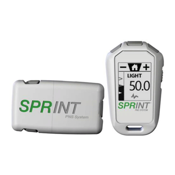
Chapter 2: System Overview 2 System Overview 2.1) System Components ® The SPRINT PNS System is made up of sterile and non-sterile components. * Indicates that two (2) of each component will be included for a dual lead system. ✎ NOTE: Components not shown to scale. 11 | SPRINT ®... - Page 12 Chapter 2: System Overview Sterile Components 1. Percutaneous Sleeve: Part of the MicroLead™ OnePass Introducer™ System, the Percutaneous Sleeve is used for testing stimulation and placing the MicroLead. 2. Stimulating Probe: Part of the MicroLead™ OnePass Introducer™ System, the Stimulating Probe is used to test stimulation prior to placing the MicroLead.
-
Page 13: Programming Tools Overview
Chapter 2: System Overview 13. Mounting Cradle: Adhesive pad that holds the MicroLead Connector in place near the MicroLead exit site to minimize the potential for lead dislodgement. 14. Rechargeable Battery: The power source used to run the Pulse Generator. 15. - Page 14 Chapter 2: System Overview The Hand-Held Remote is not able to access some programming features that are available via the Clinical Programmer. To unlock the Hand-Held Remote: Move the Lock/Unlock Switch to the up position. To lock the Hand-Held Remote: Move the Lock/Unlock Switch to the down position.
- Page 15 Chapter 2: System Overview ✎ NOTE: When stored for extended periods of time, the Clinical Programmer should be stored in a cool, dry location. 15 | SPRINT ® PNS System – Clinician Instruction for Use [L0090-MAN-000 Rev F]...
-
Page 16: Procedure Preparation
Chapter 3: Procedure Preparation 3 Procedure Preparation 3.1) Procedural Precautions These instructions are intended to provide the clinician with considerations, but are not intended as definitive descriptions of the lead placement technique. The clinician, based on standard clinical practice, should determine lead placement decisions and technique. MicroLead Insertion Site Considerations: As necessary, the lead insertion site should be adjusted to meet these criteria: Leads are only intended to be placed in the back and/or extremities. -
Page 17: Gather Components
Chapter 3: Procedure Preparation 3.2) Gather Components Inspect all packaging for any signs of damage and lay out the components for easy access. Components provided for MicroLead Placement Pulse Generator with Rechargeable Battery (non-sterile) Mounting Pad (non-sterile) Hand-Held Remote (non-sterile) ... -
Page 18: Prepare The Microlead Exit Site(S)
Chapter 3: Procedure Preparation 3.5) Prepare the MicroLead Exit Site(s) 1. With the patient appropriately positioned, clean the skin following your institution’s guidelines for aseptic technique. Clip (do not shave) hair as necessary. 2. If desired, administer local anesthetic around the planned insertion site(s) for the MicroLead. Local anesthesia may be provided at the discretion of the clinician. - Page 19 Chapter 3: Procedure Preparation 4. Remove Mounting Pad adhesive liner. Attach the Mounting Pad with Pulse Generator onto clean skin outside of the sterile field, in an area away from motor points and away from the lead insertion site. Sensations of motor activity may occur beneath the Mounting Pad and Pulse Generator.
-
Page 20: Microlead Placement & System Set-Up
Chapter 4: MicroLead Placement & System Set-Up 4 MicroLead Placement & System Set-up 4.1) Identifying Lead Placement Target using the OnePass Introducer™ System 1. Locate the target peripheral nerve. (see Appendix G: Lead Placement in Proximity to Peripheral Nerves for example lead placements) 2. - Page 21 Chapter 4: MicroLead Placement & System Set-Up 3. Insert the Percutaneous Sleeve with Stimulating Probe through the skin in a location that provides access to the target nerve, using ultrasound or fluoroscopic guidance as appropriate. 4. Connect the Stimulating Probe to the Pulse Generator. If the connection is too short, use an appropriate length Extension Cable.
-
Page 22: Testing Stimulation
Chapter 4: MicroLead Placement & System Set-Up 4.2) Testing Stimulation During the initial lead placement, use the Hand-Held Remote OR the Clinical Programmer to test stimulation with the Stimulating Probe. Refer to Section 4.2.1 below if you choose the Hand-Held Remote or 4.2.2 if you wish to use the Clinical Programmer. - Page 23 Chapter 4: MicroLead Placement & System Set-Up Remote Screens Instructions This is an instructional screen that appears for a set amount of time. To pause stimulation, press the button. Press to continue. The button will appear as an option only when stimulation is paused.
- Page 24 Chapter 4: MicroLead Placement & System Set-Up Remote Screens Instructions NOTE: The intent of the Fast Cycle approach is to allow for identification of changes in muscle tension as stimulation intensity is increased. This cycling approach is not available for procedures in which the 100 Hz frequency is used.
- Page 25 Chapter 4: MicroLead Placement & System Set-Up Remote Screens Instructions Once the desired level of stimulation has been reached, press the button to turn stimulation OFF, then press the button to continue. With stimulation OFF, unlock the lead connector and deploy the lead. Re- connect the lead connector to the lead and confirm that the lead is in the desired location by testing stimulation again.
- Page 26 Chapter 4: MicroLead Placement & System Set-Up 4.2.2) Testing Stimulation with the Clinical Programmer Tablet DUAL LEAD SYSTEM: Follow the instructions below, testing the first MicroLead (used with the light gray connector cables). After connecting the light gray lead connector to the first MicroLead, press “Next”...
- Page 27 Chapter 4: MicroLead Placement & System Set-Up Press and hold the button on the side of the Pulse Generator until it beeps and begins flashing blue (about 8 seconds). The Pulse Generator will appear in the Available Devices section at the bottom of the screen. If no devices are shown, select “start scan”.
- Page 28 Chapter 4: MicroLead Placement & System Set-Up Select the desired frequency (12Hz or 100Hz) appropriate for the therapeutic application. For 12 Hz, the goal is generally to induce a sense of tension in the muscle. At 100 Hz, the goal is generally to produce a comfortable tingling sensation.
- Page 29 Chapter 4: MicroLead Placement & System Set-Up Select Start Stim to begin testing stimulation. Adjust the intensity as desired by using the (–) and (+) arrows. The number displayed between them is the intensity level. The intensity scale ranges from 1 (minimum possible intensity) to 100 (maximum possible intensity).
- Page 30 Chapter 4: MicroLead Placement & System Set-Up Once the desired level of stimulation has been reached, stop stimulation by pressing the Stop Stim button and select Next to continue. NOTE: If desired response cannot be obtained, stop stimulation, set the intensity as low as possible and adjust position as needed before testing again.
- Page 31 Chapter 4: MicroLead Placement & System Set-Up Select Start Stim to begin testing stimulation. Adjust the intensity as desired by using the (–) and (+) arrows. The number displayed between them is the intensity level. The intensity scale ranges from 1 (minimum possible intensity) to 100 (maximum possible intensity).
- Page 32 Chapter 4: MicroLead Placement & System Set-Up Select Next to continue with testing the second lead if performing a Dual Lead Placement or Select Set Min/Max for establishing therapy settings (see Section 4.4.2 Establishing Therapy Settings with the Clinical Programmer). Note: graphic is shown with a Dual Lead Placement 32 | SPRINT ®...
-
Page 33: Confirming Location & Placing The Microlead(S)
Chapter 4: MicroLead Placement & System Set-Up 4.3) Confirming Location & Placing the MicroLead(s) Handle the SPRINT MicroLead, its Introducer, Percutaneous Sleeve and Stimulating Probe with extreme care. They may be damaged by excessive traction or sharp instruments. Do not bend, kink, or stretch the lead body or its Introducer, Percutaneous Sleeve, or ... - Page 34 Chapter 4: MicroLead Placement & System Set-Up 1. Once the optimal location for the electrode has been determined, disconnect the Stimulating Probe from the Pulse Generator. 2. Unlock the Stimulating Probe from the Percutaneous Sleeve by rotating the hub counter- clockwise and remove the Stimulating Probe, leaving the Percutaneous Sleeve in the tissue.
- Page 35 Chapter 4: MicroLead Placement & System Set-Up 4. In order to confirm MicroLead location, insert the loose end of the MicroLead into the entry site on the hinged side of the MicroLead Connector. Shut the snap closure of the MicroLead Connector to de-insulate the MicroLead and create an electrical connection.
- Page 36 Chapter 4: MicroLead Placement & System Set-Up 7. Deploy the MicroLead by applying pressure to the skin near the MicroLead exit site. With the other hand, gently retract the Percutaneous Sleeve with Introducer, leaving the MicroLead implanted. 8. Re-insert the loose end of the MicroLead into the entry site on the hinged side of the MicroLead Connector assuring that adequate lead length exists between the skin exit site and the MicroLead Connector to create a strain relief loop (3-5 cm is typical).
- Page 37 Chapter 4: MicroLead Placement & System Set-Up 9. Shut the snap closure of the MicroLead Connector to de-insulate the MicroLead and create an electrical connection. 10. Trim the excess MicroLead wire. 11. Slide the MicroLead Connector into the Mounting Cradle, then adhere the Mounting Cradle to the skin.
- Page 38 Chapter 4: MicroLead Placement & System Set-Up 12. Cover the MicroLead insertion site and Mounting Cradle with the non-adhesive center portion of the Waterproof Bandage, leaving the plug end of the MicroLead Connector exposed. 13. Connect the Magnetic Coupler to the Pulse Generator, using a long or short extension cable if needed.
-
Page 39: Establishing Therapy Settings
Chapter 4: MicroLead Placement & System Set-Up 4.4) Establishing Therapy Settings Use the Hand-Held Remote OR the Clinical Programmer to establish therapy settings for use by the Patient. Refer to Section 4.4.1 below if you choose the Hand-Held Remote or 4.4.2 if you wish to use the Clinical Programmer. - Page 40 Chapter 4: MicroLead Placement & System Set-Up Single-Lead Dual-Lead Instructions The screen will briefly display Minimum is Set, then advance automatically to enable setting of the maximum stimulation intensity level. To proceed to setting the maximum stimulation, press button to continue. To return to setting the minimum stimulation intensity level press the button.
- Page 41 Chapter 4: MicroLead Placement & System Set-Up Single-Lead Dual-Lead Instructions The screen will briefly display Maximum is Set. Dual Lead System: Continue setting stimulation parameters for the second MicroLead (used with the dark gray connector cables). Setting parameters for the second (dark) MicroLead repeats the steps used to set the parameters for the first MicroLead.
- Page 42 Chapter 4: MicroLead Placement & System Set-Up 4.4.2) Establishing Therapy Settings using the Clinical Programmer Tablet If the Clinical Programmer Tablet is not connected to the Pulse Generator, turn on the tablet and connect to the Pulse Generator now (see Section 4..2.2 for instructions on connecting to the Pulse Generator).
- Page 43 Chapter 4: MicroLead Placement & System Set-Up To adjust favorites that allow the patient to easily reach a desired stimulation level, tap one of the boxes below the word FAVORITES. This will set the currently displayed stimulation intensity value as a favorite. You can set up to 3 favorites. To remove a favorite, tap on the box of the favorite you wish to delete.
-
Page 44: Patient Counseling
Chapter 5: Patient Counseling 5 Patient Counseling Review the Patient Instructions for Use, including the warnings and precautions listed in the Patient Instructions for Use, with the patient. Also discuss the following topics with the patient to ensure ® optimal use of the SPRINT PNS System. -
Page 45: Air Travel
Chapter 5: Patient Counseling Check the skin beneath the Waterproof Bandage for signs of irritation, redness, or infection. If signs of infection are present, a healthcare provider should be notified. 5.3) Air Travel The Pulse Generator’s Rechargeable Batteries contain lithium. Storage and packing the batteries during air travel must comply with all federal and international aviation regulations for spare, uninstalled, lithium batteries in carry-on bags. -
Page 46: End Of Treatment
Chapter 6: End of Treatment 6 End of Treatment 6.1) MicroLead(s) Withdrawal To withdraw the MicroLead(s): 1. Turn stimulation OFF. 2. Disconnect and remove all external system components. 3. If desired, cut the MicroLead close to the MicroLead Connector between the skin and the MicroLead Connector, ensuring that the potion of MicroLead that remains exposed may be easily grasped. -
Page 47: System Disposal
Chapter 6: End of Treatment It is possible that a fragment (or fragments) of the MicroLead could break off and remain in the body after removal. Upon removal, inspect the MicroLead for signs of damage. If a MicroLead fragment remains after lead removal, clinical judgment should be used to determine if the fragment should be removed. -
Page 48: Appendix A Troubleshooting
Appendix A: Troubleshooting APPENDIX A Troubleshooting Problem Possible Causes Actions to be Taken Mounting Pad is not Skin is not clean Clean skin with mild soap and adhering to skin water and allow skin to dry OR wipe skin with an alcohol pad and allow to dry OR apply a drop of tap water to adhesive side of mounting pad OR use a... - Page 49 Appendix A: Troubleshooting Problem Possible Causes Actions to be Taken Pulse Generator Screen (Remote or Hand-Held Remote or Clinician Ensure the component is Clinical Programmer) Programmer out of range within arm’s length of the shows “Wireless Pulse Generator; Error” Hand-Held Remote: Toggle lock switch down to retry connection Clinician Programmer: Attempt...
- Page 50 Appendix A: Troubleshooting Problem Possible Causes Actions to be Taken Stimulation will not Rechargeable battery is too low Replace and recharge the turn on Rechargeable Battery Lead Connect Error See troubleshooting section “Screen shows Lead Connect Error” Hand-held remote Magnetic Coupler or Short or Long Check connection between Screen shows “Lead Extension not fully connected to Pulse...
- Page 51 Appendix A: Troubleshooting Problem Possible Causes Actions to be Taken MicroLead breaks MicroLead is damaged or broken at Use the Connector Key to away from the connection to MicroLead Connector remove the MicroLead from MicroLead Connector the MicroLead Connector; Move the MicroLead Connector approximately 1 cm closer to the MicroLead exit site, then close the MicroLead...
-
Page 52: Appendix B Optional Features When Using The Clinical Programmer
Appendix B: Establishing Advanced Therapy Settings Using the Clinical Programmer APPENDIX B Optional Features when Using the Clinical Programmer B.1) Optional Features Several optional features are available while in the View/Edit Program screen. These features are described below, and can be accessed by pressing the icon (menu shown below). - Page 53 Appendix B: Establishing Advanced Therapy Settings Using the Clinical Programmer Intensity testing option using the directly set minimum and maximum intensities Press the button to return to directly controlling amplitude and pulse duration to change the minimum and maximum. Tap the Save and Finish button to save your changes in the direct parameter control.
-
Page 54: Appendix C Contacting Spr Therapeutics
Appendix C: Contacting SPR APPENDIX C Contacting SPR Therapeutics Via Mail: SPR Therapeutics, Inc. 22901 Millcreek Blvd, Suite 110 Cleveland, OH, 44122 USA Via Telephone: Toll Free: 844-378-9108 Via Fax: 216-803-0777 Via Email: support@sprtherapeutics.com 54 | SPRINT ® PNS System – Clinician Instruction for Use [L0090-MAN-000 Rev F]... -
Page 55: Appendix D Technical Description And Specifications
Technical Description and Specifications Technical Description The SPRINT PNS System is a neurostimulation system using one or two percutaneous leads and a skin worn Pulse Generator to deliver low levels of pulsing electrical currents to selected nervous system tissue. The Pulse Generator has a rechargeable battery incorporating a Lithium Ion polymer cell. - Page 56 Appendix D: Specifications SPRINT Test Needle (REF 9645-2575 & 9645-24125) Parameter Specification 7.5 cm (REF 9645-2575) Needle Length 12.5 cm (REF 9645-24125) Sterility Provided sterile by Ethylene Oxide and non-pyrogenic SPRINT Stimulating Probe (REF 80048) Parameter Specification Probe Length 12.3 cm Sterility Provided sterile by Ethylene Oxide and non-pyrogenic SPRINT Percutaneous Sleeve (REF 80022)
- Page 57 Appendix D: Specifications Parameter Specification charge delivered accurate to +/- 15%) Maximum Charge Density at 0.4 µC/mm (when in use with the SPRINT MicroLead) Stimulating Electrode Maximum Current Density at 0.06mA / cm (1.4mA / 25cm Return Electrode (Pad) Range of Load Impedance 200Ω...
- Page 58 Appendix D: Specifications Parameter Specification Charging Current 115mA. SPRINT Recharging Base Power Supply (REF 9616) Parameter Specification Size Approximately 3.9cm X 3.3cm X 2.4cm Commercially available USB Power Adapter (with integral plug cap for Description US market) Safety Certifications UL (60950-1); FCC Part 15 class B; Output 5.00V (+/- 0.24V) at up to 1.0A DC (0.15A is required) Mains Power...
- Page 59 Appendix D: Specifications Parameter Specification Wireless Communications Bluetooth 4.0 Internal Battery Rechargeable Lithium-Ion Battery Operating Temperature 0°C to +35°C (32°F to 95°F) Safety Certifications CE Marked; IEC 60950-1 compliant; FCC Part 15 class B; Input 5.0V DC SPRINT Clinical Programmer Charger (REF 9631) Parameter Specification Size...
- Page 60 Appendix D: Specifications Parameter Specification Light Gray (REF 9680) Colors Dark Gray (REF 9681) Proximal end: touchproof keyhole connector Connector Distal end: touchproof keyhole connector SPRINT Long Extensions (REF 9685 & 9686) Parameter Specification Light Gray (REF 9680) Colors Dark Gray (REF 9681) Proximal end: touchproof keyhole connector Connector Distal end: touchproof keyhole connector...
-
Page 61: Appendix E Symbols & Messages
Appendix E: Symbols & Messages APPENDIX E Symbols & Messages Table A: Hand-Held Remote Symbols and Messages Table A explains the symbols and messages that appear on the Hand-Held Remote and its screen. Symbol or Message Description Stimulation on/off button Stimulation is on Stimulation is off Increase... - Page 62 Appendix E: Symbols & Messages Table B: Pulse Generator Lights and Tones Table B explains the lights and tones that are output by the Pulse Generator. Light or Tone Description Short beep Newly inserted Rechargeable Battery high to medium charge 5 second Green light Short beep Newly inserted Rechargeable Battery low charge...
- Page 63 Appendix E: Symbols & Messages Symbol or Message Description Low Battery Pulse Generator Battery is low Recharge Battery Hardware Error Hardware/Internal error in the Pulse Generator Internal Error Full Rechargeable Battery in the Pulse Generator Mostly full Rechargeable Battery in the Pulse Generator Partially full Rechargeable Battery in the Pulse Generator Low Rechargeable Battery in the Pulse Generator;...
- Page 64 Appendix E: Symbols & Messages Symbol or Message Description Open Admin Mode (Only accessible by SPR representative) Decrease setting to the minimum possible value Increase setting to the maximum possible value Information displayed relates to the Light Gray MicroLead (MicroLead connected to the light gray MicroLead Connector and cables) Information displayed relates to the Dark Gray MicroLead (MicroLead connected to the Dark Gray MicroLead Connector and cables)
- Page 65 Appendix E: Symbols & Messages Symbol or Message Description Lot number Serial Number Use by date (YYYY-MM-DD): This product should be used before the specified day. YYYY-MM-DD Keep dry The degree of protection from water and dust offered by the Pulse IP 22 Generator and Hand-Held Remote.
-
Page 66: Appendix F Using The Stimulating Needle For Microlead Placement Procedure
Appendix F: Using the Stimulating Needle for MicroLead Placement Procedure APPENDIX F Using the Stimulating Needle for MicroLead Placement Procedure Based on physician preference, the MicroLead can be tested and placed using the Stimulating Needle in conjunction with the MicroLead Introducer. 1. - Page 67 Appendix F: Using the Stimulating Needle for MicroLead Placement Procedure 9. Once the desired location has been attained, unlock the MicroLead Connector by inserting the MicroLead Connector Key into the indented lock sites on the underside of the MicroLead Connector until the snap closure of the MicroLead Connector can be opened. Once opened, withdraw the MicroLead from the MicroLead Connector.
-
Page 68: Appendix G Microlead Placement In Proximity To Peripheral Nerves
Appendix G: MicroLead Placement in Proximity to Peripheral Nerves APPENDIX G MicroLead Placement in Proximity to Peripheral Nerves The following sections provide more detailed instructions for placing the MicroLead in proximity to several common nerves targeted for pain relief: the femoral nerve (lower extremity example), ... - Page 69 Appendix G: MicroLead Placement in Proximity to Peripheral Nerves the desired response is achieved. If the desired response cannot be obtained with the highest intensity setting, the electrode may need to be repositioned. Lower Extremity Example: Femoral Nerve Stimulation As an example, the target nerve may be the femoral nerve. The MicroLead may be advanced, generally under ultrasound guidance, to the target location using an approach similar to those used for delivering regional anesthesia to the femoral nerve.
- Page 70 Appendix G: MicroLead Placement in Proximity to Peripheral Nerves The lead should be placed in the optimal location, following the instructions in Section 4: Lead Placement and System Set-up. Back Example: Medial Branch of Dorsal Ramus Stimulation As an example, the target nerves may be the medial branches of the dorsal rami of the lumbar spinal nerve located in the multifidus (paraspinal muscle).
-
Page 71: Appendix H Limited Warranty
APPENDIX H Limited Warranty SPR warrants to Buyer that Products manufactured by SPR that are sold to Buyer will be free from defects in material and workmanship under normal use consistent with regulatory clearance for the earlier of: (a) the expiration date of the Products;... - Page 72 22901 Millcreek Blvd, Suite 110 Cleveland, OH, 44122 USA Call 844-378-9108 | Fax 216-803-0777 www.sprtherapeutics.com support@sprtherapeutics.com © 2018 - SPR Therapeutics, Inc.
Need help?
Do you have a question about the SPRINT PNS System and is the answer not in the manual?
Questions and answers
Wirelessly error