Table of Contents
Advertisement
Installation, Operation &
Maintenance
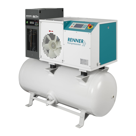
RS-B
Please read carefully before commissioning and follow
instructions. Keep in a safe place for future use.
Manual
RENNER GmbH Kompressoren
Emil-Weber Str. 32
D-74363 Gueglingen
Tel: +49 (0)7135 931 93 0
Fax: +49 (0)7135 931 93 50
info@renner-kompressoren.de
www.renner-kompressoren.de
GB
Advertisement
Table of Contents

Subscribe to Our Youtube Channel
Related Manuals for Renner Kompressoren RS-B


Summary of Contents for Renner Kompressoren RS-B
- Page 1 Installation, Operation & Manual Maintenance RS-B Please read carefully before commissioning and follow instructions. Keep in a safe place for future use. RENNER GmbH Kompressoren Emil-Weber Str. 32 D-74363 Gueglingen Tel: +49 (0)7135 931 93 0 Fax: +49 (0)7135 931 93 50 info@renner-kompressoren.de...
-
Page 2: Table Of Contents
Table of contents Chapter 0 Subject page General information General information Structure and use of this manual Intended usage / misuse Requirement of the user Personnel responsibilities Chapter 1 Subject page Safety advice Symbols Basic safety advice Accident conduct Chapter 2 Subject page Machine... -
Page 3: Table Of Contents
Table of contents (continuation) Chapter 3 Subject page Installation & putting into Compressor installation operation Connections Putting into operation Kapitel 4 Subject page Operating / normal Control instrumentation RENNERlogic Control instrumentation RENNERtronic Control instrumentation RENNERtronic plus Compressor startup / normal use To stop the compressor Failures during operation 4-10... -
Page 4: Table Of Contents
Chapter 5 Subject page Maintenance What to take into account Remove faults Venting the compressor system Cleaning work Checking oil level Change of oil filter Changing oil Cleaning oil level sight glass 5-10 Cleaning oil cooler 5-11 5.10 Checking safety valve 5-12 5.11 Tensioning and changing drive belt(s) - Page 5 Appendixes Subject Data sheet CE Conformity Declaration AW1 Maintenance check AW2 Motor bearings AW3 Maintenance work Pressure switch Refrigeration dryer (optional) Table of contents Content-...
-
Page 6: Information
Chapter 0 General Information Hereunder you will find general information relating to the Contents following subjects: Utilisation of the INSTALLATION, OPERATION & MAINTENANCE MANUAL Compressor Operation and Usage Personnel responsibilities Survey This chapter relates to the following subjects: Subject Page General information Structure and use of the manual Intended Usage... -
Page 7: General Information
0.1 General Information General information regarding this manual. Contents This manual is applicable to the following compressor: Validity Compressor Detail Classification Type Screw compressor Year of construction Serial number Model Location RENNER GmbH compressors Manufacturer Emil-Weber-Strasse 32 D-74363 Gueglingen June 2016 Date of issue Safe-keeping and This manual should be kept in a clean safe condition and... - Page 8 0.1 General Information (Continuation) This documentation contains copyrighted information. Copyright Without prior consent of RENNER GmbH this information must not be photocopied, duplicated, translated or put on data carrier neither as a whole or part document. RENNER GmbH reserves all further rights. For safety reasons any modification or alteration may be Modification of the permitted only after having received the agreement of the man-...
-
Page 9: Structure And Use Of This Manual
0.2 Structure and use of this manual The following information relates to the structure and use of this Contents manual. This manual contains the following chapters: Chapter Chapter Summary General Information regarding: – the manual, – its usage – personnel responsibilities Definition of the symbols used Basic safety instructions Description and function of the compressor... -
Page 10: Intended Usage / Misuse
0.3 Intended usage / misuse The intended usage of the compressor is described Definition: Persons are regarded as authorized, when they have received adequate training/instruction and is then charged with defined authorized persons work on or with the compressor... Keys to the guard doors must only be made accessible to authorized persons. -
Page 11: Requirement Of The User
0.4 Requirement of the user Hereafter the duties and obligations of the user are outlined Contents when operating the machines The user has to particularly ensure that Safety of the plant the compressor must be used only according to Manu- facturer recommendations in conjunction with all current health and safety regulations the compressor must be operated only when in faultless... -
Page 12: Personnel Responsibilities
0.5 Personnel responsibilities The requirements in regard to personnel responsibilities are Contents as follows. Duty of operating The personnel must carry out the following duties: personal to control and inspect the compressor as to its faultless and safe function (see chapter 2.1) to operate the compressor according to the operating points previewed to recognize and delete or report respectively disturbances... -
Page 13: Basic Safety Advice
Chapter 1 Safety Advice This chapter informs you about Contents Definition of the symbols used. Basic advice as to the safe handling of the compressor. Advice regarding accidents. Important advice! It must be clearly understood that the safety advice given in this manual should only be used as an additional aid to the national safety accident prevention rules and laws currently in force. - Page 14 1.1 Symbol Symbol definitions Contents Danger! This symbol relates to the danger of life and health of people Dangers to life will be particularly related to by using the expression: danger for life. Danger! This symbol relates to danger for life and health of people due to electric voltage.
- Page 15 1.2 Basic safety advice Hereafter you will find basic safety advice for the safe handling Contents of the compressor. Danger! To minimise risk of personal injury, damage to equipment or property, strictly follow the remedial actions stated below. Possible danger Remedial action Remaining dangers You should only operate this...
- Page 16 1.2 Basic safety advice (continuation) Danger! Please strictly follow the under mentioned safety advice to avoid the danger of electrical shock or personal injury. Possible danger Remedial actions Danger of life Do not touch live cables or Danger to people by an connections.
- Page 17 1.2 Basic safety advice (continuation) Attention! To minimise risk of personal injury, damage to equipment or property, strictly follow the remedial actions stated below. Possible damage Measures for prevention Physical injury of the Do not remove or make personnel and damage inoperative any safety device to the compressor due Rectify defects immediately...
- Page 18 1.3 Accident Conduct Hereafter you will get to know which measures must be taken at Contents accidents or disasters (e.g. fire or explosion) Preparations for Please undertake the following measures at regular time intervals so as to be prepared in case of an accident: appropriate help at accidents Take part on regular basis in First - Aid courses in order...
-
Page 19: Machine Description
Chapter 2 Machine description This chapter covers the following: Content definition of the safe access points for operating the com- pressor, overview of the compressor and its control instrumentation, technical data. This chapter is subdivided as follows: Overview Subject Page Authorised access points Safety devices Compressor unit... - Page 20 2.1 Authorised access points This section defines the safe access points for operating the Content compressor and for carrying out minor inspection and mainte- nance work. Other access points are not intended for operating the com- Important pressor and are therefore not permitted as operator stations! Note! Safe operation can only be guaranteed from the operator termi- nals specified.
- Page 21 2.1 Authorised access points (cont.) The following access points only are provided for the operation Description of the of the machine: access points Operation ... Actions permitted ... of the control panel Check working pres- sure Check oil and operating temperature Read operating hours Switch compressor on...
- Page 22 2.2 Safety devices This section provides an overview of the major compressor el- Content ements and their functions. Figure safety devices The following safety devices are fitted to the outside of the Description of the compressor: safety devices Item Description Function Emergency stop Stops compressor immediately in...
- Page 23 2.3 Compressor unit Figure compressor unit Description of the After removing the front walls of the compressor, you will see the most important components of the unit: compressor unit Item Description Function Suction air filter Is used to filter suction air cartridge Separator cartridge Filters the finest residue oil...
- Page 24 2.3 Compressor unit (cont.) Air end (item 8) Description The direction of rotation of the air end is to the left (anti- aggregate clockwise) when looking from the front-side on to the shaft (see components picture). Pay attention to the directional arrow on the side of the air end with the sign D.
- Page 25 2.3 Compressor unit (continuation) 2) As a “non return valve“ it prevents at the same time the re- Description unit verse flow of compressed air from the air mains or the air ves- components sel, back into the compressor unit. Due to this function the (contd.) compressor unit is totally pressure relieved once it is stopped.
- Page 26 2.3.2 Compression unit (continuation) Oil scavenge window / oil scavenge non-return valve Description: The oil scavenge non-return valve prevents the oil separator Compression unit cartridge from flooding by scavenging oil from the air end. components (con- tinuation) Oil filter (item 12) The oil filter (cartridge) cleans the compressor oil from impuri- ties.
- Page 27 2.4 Instrumentation Panel RENNERlogic Figure Instrumentation panel RENNERlogic The following controls are found on the instrumentation panel: Description of the Instrumentation panel RENNERlogic Item Description Function Start button Switches the compressor on Stop button Switches the compressor off Emergency stop Switches the compressor off in case of emergency Operating hour...
- Page 28 2.5 RENNERtronic Control (Optional) The “RENNERtronic” controls and monitors the entire workings Content of the compressor. It is possible to set or change a number of parameters and functions.=> please also note the enclosed instructions Figure Control RENNERtronic The "RENNERtronic" control features the following Instrumentation instrumentation controls: components:...
- Page 29 2.6 RENNERtronic plus Control (Optional) The “RENNERtronic plus” controls and monitors the entire Content workings of the compressor. It is possible to set or change a number of parameters and functions.=> please also note the enclosed instructions Figure Control RENNERtronic plus The "RENNERtronic plus"...
- Page 30 2.7 Refrigerant drier (optional) Contents This section provides a brief overview of the refrigeration drier, installed as an optional feature. Diagrams of refrigerant drier 1.) Compressed air inlet 6.) Electrical connections 2.) Cpmpressed air outlet 7.) Maintenance access 3.) Refrigerant air intake 8.) Mounting holes 4.) Refrigerant air outlet E100.) On-off switch...
- Page 31 Description The refrigerant drier also has a cooling unit to cool the com- pressed air. The unit also removes moisture from the com- Refrigerant drier pressed air. The resulting condensate is drained off using a condensate separator. Attention! Please see the explanations in chapter 4 and the KT Appendix as well as the manufacturer’s instruction manual.
-
Page 32: Compressor Installation
Chapter 3 Installation and commissioning This chapter contains the most important information on trans- Content porting, installing and storing the compressor. General Infor- The installation plan and the technical data of this specific screw compressor model can be ordered from RENNER GmbH. mation The compressor is delivered on a euro-pallet, packaged in a carton and labelled. -
Page 33: Connections
3.1 Compressor installation This section contains important instructions which you need to Content observe in order to safely install the compressor and to prevent damage or malfunction. Warning! Follow the safety instructions! Always remain outside the danger zone of a raised load! Compressor instal- Key word Ensure that... - Page 34 3.2 Connections This section covers important instructions which you need to Content observe in order to safely connect the compressor to the com- pressed air system as well as the electrical supply. Warning! Before connecting the machine to the compressed air system, all conduits and hose connections inside the compressor must be checked and, if necessary, retraced.
- Page 35 3.2 Connections (continuation) B Electrical connection Attention! All wiring work on the controls, and the compressors have to be carried out in consideration of the 5 safety rules. Only the connection to the electricity supply is now required for the machine which is now ready to use with all conduits in- stalled.
-
Page 36: Putting Into Operation
3.3 Compressor start-up This section covers important information which you need to Content observe in order to start up the compressor safely. Each component of the machine is tested at the factory in con- General points tinuous operation after the final assembly. The test ensures that the components indicate the data given and operate fault-free. - Page 37 3.3 Compressor start-up (continuation) When first starting up the machine, as well as after each Checking the change to the electrical feed line, the rotation of the screw com- rotational direction pressor must be checked. INFO The rotation of the V-belt pulley must follow the direction of the attached arrows! If necessary, reconnect the connecting cable (electrician).
- Page 38 3.3 Compressor start-up (continuation) Carry out a test run so that the oil can be distributed throughout Test run the machine. INFO Conduct a Step Operation: Figure / Expl. test run Open the shut-off valve. Press the start button and let the machine run for approx.
- Page 39 Chapter 4 Operation / Normal use This chapter covers the information required for normal opera- Content tion of the compressor. Overview This chapter is subdivided into the following sections: Subject Page Control instrumentation RENNERlogic Control instrumentation RENNERtronic Control instrumentation RENNERtronic plus Starting normal operation Switching off the compressor Remedying malfunctions in normal operation...
-
Page 40: Control Instrumentation Rennerlogic
4.1 Control instrumentation RENNERlogic This section provides an overview of the instrumentation control Content RENNERlogic. Figure Instrumentation components RENNERlogic Function The control components have the following function(s): Instrumentation components Item Description Function/Use RENNERlogic Start button Starts the compressor Note: The main switch must be switched on. -
Page 41: Control Instrumentation Rennertronic
4.2 Control instrumentation RENNERtronic This section provides an overview of the instrumentation control Content RENNERtronic. Figure Instrumentation control RENNERtronic The instrumentation control has the following function(s): Function Instrumentation control Item Description Function RENNERtronic Compressor ON / Switches the compressor on Start LED (green) Service LED... - Page 42 Item Description Function Enter Select a menu item. Confirm or save entries or changes. LED (red) Fault / maintenance LED Quit Quit discards inputs and ends a selected menu item. It also acknowledges warning and error messages. Display Displays the parameters and the error/warning messages.
-
Page 43: Control Instrumentation Rennertronic Plus
4.3 Control instrumentation RENNERtronic plus This section provides an overview of the instrumentation control Inhalt RENNERtronic plus. Figure Instrumentation control RENNERtronic plus Function The instrumentation control has the following function(s): Instrumentation Pos. Bezeichnung Funktion control RENNERtronic LED (green) Service LED plus Compressor ON / Switches the compressor on... - Page 44 4.4 Starting normal operation The following section explains how to start the compressor and Content contains essential points for normal operation. Danger! There are moving parts inside the compressor housing which can cause serious injuries. Never operate the compressor with the housing open! Check the following points before starting the compressor: Before starting the compressor...
- Page 45 4.4 Starting normal operation (continuation) Monitor normal Step Operation Figure / Expl. operation Oil temperature and (contd.) operating temperature The oil temperature and operating temperature must not exceed 110°C. If 110°C is exceeded the compressor will cut out automatically. Important! Should the compressor fail to cut out automati- cally it must be switched...
- Page 46 4.5 Switching off the compressor This section explains how to switch off the compressor in nor- Content mal operation and/or at the end of operations. Stop normal To switch off the compressor carry out the steps below in the order listed: operation Step Operation...
- Page 47 4.5 Switching off the compressor (continuation) If you want to shut off the compressor completely: Completely shut off (e.g. after completing the work), then in addition to the above steps, you must also turn off the main switch. Note: Switching the machine off via the red emergency stop button can lead to the oil frothing up in the separator tank.
- Page 48 4.6 Remedying malfunctions in normal operation This section contains advice on remedying malfunctions. Content Danger! Human error in remedying faults or lack of professional training can lead to serious damage to property or physical injury. It is therefore essential that faults are rectified by duly qualified persons.
- Page 49 4.6 Remedying malfunctions in normal operation (continuation) Malfunctions Fault Possible Cause Remedy (contd.) System starts Check and correct • Time for star-delta connec- with difficulty time setting, tion too long or too correct setting short 3-6 seconds, adjust on Relay K 1T •...
- Page 50 4.6 Remedying malfunctions in normal operation (continuation) Malfunctions Fault Possible Cause Remedy (contd.) Motor overload Eliminate reason for • Blocked tripping (therm. seizure system overcurrent relay) Check supply line • Phase failure has stopped the Check and adjust • Motor over- system overload setting;...
- Page 51 4.6 Remedying malfunctions in normal operation (continuation) Malfunctions Fault Possible Cause Remedy (contd.) Oil in compressed air Have oil scavenge • Oil scavenge line and system cleaned nozzle in oil sight glass clogged • Separator cartridge Check cartridge and defective replace if necessary •...
- Page 52 4.6 Remedying malfunctions in normal operation (continuation) Malfunctions Fault Possible Cause Remedy (contd.) Intake regulator Install new actuating • Actuating cylin- does not close at cylinder, check sole- der defective, no discharge pressure noid valve control pressure Clean nozzle • Nozzle blocked or frozen Pressure vessel not Change non-return...
- Page 53 Chapter 5 Maintenance instructions This chapter contains information on the maintenance work Content required. This chapter is subdivided as follows: Overview Subject Page What to take into account Remove faults Venting the compressor system Cleaning work Checking oil level Changing oil filter Changing oil 5-10 Cleaning oil level sight glass...
- Page 54 5.1 What to take into account This section contains general information to be heeded during Content servicing and maintenance work. Personnel Servicing and maintenance work may only be carried out by duly qualified personnel. requirement The specific personnel requirements are set out in Chapter 0. Danger! It is essential to adhere to the following safety instructions in order to avoid all risks of personal injury or death:...
-
Page 55: What To Take Into Account
5.1 What to take into account (continued) The following steps must be carried out after completing the After completion of work: work Step Operation Follow the maintenance schedule and complete the inspection sheets, activity logs, etc. (see Appendix W “Maintenance Check”). Check that the safety devices are working correctly. - Page 56 5.1 What to take into account (continued) Take the standard safety precautions and proceed with great General care when carrying out any servicing work. Notes Please follow especially the points below: Servicing work to be carried out by qualified personnel only. Correct tools only to be used for servicing work.
-
Page 57: Remove Faults
5.2 Remove faults This section covers general points on troubleshooting and con- Content tains references to relevant sources of information. Danger! Always take measures to ensure that the machine can be shut off in an emergency by a second person. You may only rectify faults or carry out checks if you are duly qualified (specialist training in mechanical or electrical engineering). -
Page 58: Venting The Compressor System
5.3 Venting the compressor system This section outlines the main points to be taken into account Contents when the unit has to be vented. The pressure has to be removed from the unit before all servic- Why vent? ing and maintenance work. The unit vents automatically when switched off but if there is a fault the unit might remain pressur- ised even after being switched off. -
Page 59: Cleaning Work
5.4 Cleaning work The following section contains information on cleaning the Content compressor and the air filter. In terms of general cleaning, vacuum the unit or wipe it with a General points damp cloth. Check the intake passage regularly, where neces- sary removing any leaves, dust, dirt or similar matter in the in- terests of an efficient air supply. -
Page 60: Checking Oil Level
5.5 Checking oil level This section outlines the procedure for checking the oil level in Content the compressor. The level in the oil tank is a key factor in the operational safety General points of the unit. Due diligence should be exercised in conducting the following checks at the specified times. - Page 61 5.6 Changing oil filter This section outlines the procedure for changing the oil filter. Content An oil filter may only be changed when the unit is switched off Important note! and fully depressurised and without power. Changing the oil Step Operation filter Switch off the unit and take measures to prevent it...
-
Page 62: Changing Oil
5.7 Changing oil This section outlines the procedure for changing the oil. Content The oil may only be changed when the unit is switched off and Important note! fully depressurised! The unit should be at operating tempera- ture (approx. 60°C - 80°C) when the oil change is carried out. The unit should be run with the type of oil best suited to its op- eration. -
Page 63: Cleaning Oil Cooler
5.8 Cleaning oil return window This section outlines the procedure for cleaning the oil scav- Content enge sight gauge (optional extra). The oil scavenge sight gauge is screwed onto the line on the General points separator cartridge. Cleaning the oil Step Operation level indicator... - Page 64 5.10 Check the safety valve Check After 2000 operating hours - however at least 1x a year General points The check process may only take a few seconds and be completed only by hand Caution risk of injury! Scalding danger by escaping hot air-oil mixture Since this is a dangerous process, please proceed with extreme caution.
- Page 65 5.11 Tensioning and changing of drive belts(s) This section outlines the procedure for tensioning and/or chang- Content ing the V-belt. The belt can be set to the optimum tension using the adjust- General points mentscrews on the air end block. Fig.
- Page 66 Change the Step Operation V-belt How to "tighten a V-belt", step 1 and 2 Loosen adjustment screw, remove old belts Insert the new V-belt (please only use RENNER orig- inal spare parts). As described above in “Thighten belts”, step 3 – 6. Check for each V-belt replacement the alignment of the V- belt pulleys to each other.
-
Page 67: And Disposal
Chapter 6 Decommissioning and disposal This chapter contains important advice for (temporarily) Content decommissioning or disposing of your compressor. Survey This chapter is divided into the following sub-sections: Subject Page Decommissioning of plant Re-commissioning after storage Shut-down and disposal 6 - 1 6 Decommissioning and disposal... - Page 68 6.1 Decommissioning of plant This section contains instructions you need to follow when Content decommissioning the compressor for an extended period of time, and when subsequently returning it to operation. When decommissioning for an extended period of time, prepare the unit as follows: Decomissioning of Step Activity...
- Page 69 6.2 Re-commissioning after storage Compressor units that have been switched off, Re-commissioning decommissioned or stored away for longer than 3 months, information should not be put back into operation until the following measures have been carried out. Re-commissioning Follow the procedure outlined below to return the compressor to operation after being out of commission for 3 months or more.
- Page 70 6.3 Shut-down and disposal This section describes what you need to consider when shutting Content down and disposing of the unit. DANGER Observe the safety instructions outlined in this handbook, the instructions specified in the supplier's documentation as well as accident prevention guidelines. Danger of life! Moving or lifting the compressor should only be undertaken in a safety conscious manner.
- Page 71 6.3 Shut-down and disposal (Cont.) The following materials were predominately used in the Materials construction of the unit: Information Material Where used Batteries, NiCad-/Li • Control Copper • Cables Steel • Machine frame • Side panels and doors • Motor and components Plastic, rubber, PVC •...
- Page 72 Weight Air receiver power of oil connection Conn. db(A) m³/min m³/h mm² L x B x H 7,5 bar 10 bar RS-B 2.2 0,335 0,265 direkt 1,95 ½" 716 x 536 x 540 x-500 RS-B 3.0 0,46 0,38 direkt 1,95 ½"...
- Page 73 RENNER Serial no.: Series / type description: RS-B, RSK-B, RSD-B, RSDK-B 2,2 - 11 kW Description: Screw Compressor for generating compressed air of 7,5 to 10 bar meets all relevant provisions of the above stated guideline and the other applied guidelines (to follow) - including the changes applicable at the time of the declaration.
- Page 74 Appendix W - Maintenance Control for RS-B 3 - 11 with less than 2000 hours / year after ... years Maintenance work Fill out commissioning report Check screw connections and tighten if necessary Check that all connections are firm and tight...
- Page 75 Appendix W - Maintenance Control for RS-B 3 - 11 with more than 2000 hours / year after ... hours Maintenance work 2000 4000 6000 8000 10000 12000 14000 16000 18000 20000 Fill out Commissioning report Check screw connections and tighten if necessary...
- Page 76 Appendix W2 Maintenance of Motor Bearings This Appendix provides an overview of how motor bearings are Contents to be maintained. This description only applies to current sys- tems and may differ to the maintenance required for older mo- tors. Our compressors up to 37kW are fitted with motors having Continuously lubri- closed, continuously lubricated deep-groove ball bearings –...
- Page 77 Appendix W2 Maintenance of Motor Bearings (cont.) Motor bearings re- Our motors from 45 kW are fitted with “open” ball bearings. Motors this size and up have re-lubrication devices on the A- quiring re- and B-sides. lubrication These bearings must be re-lubricated regularly in accordance with the information given in the maintenance check sheet.
- Page 78 Appendix W2 Maintenance of Motor Bearings (cont.) The details of the bearings installed by us and the lubrication quantities to be filled (only for WEG motors) are listed below: Grease lubrica- Size Output (kW) A-side B-side quantity tion in- (grams) terval 1,5 / 2,2 6205 ZZ...
- Page 79 Appendix W 3 Manual Maintenance Work RENNER GmbH Operat. Airfilter Oilfilter Motor bearings other service work Oilseparator cartridge Oilfilling Drive belt Signature and date cartridge A + B Side (take another sheet if required) Hours cartridge Please tick the work which has been done and/or record measured data which confirm by signature . AW –...
- Page 80 Appendix ADS End Pessure Switch This chapter provides a brief overview of all the pressure switch Contents functions. Warning! From the factory side, the pressure switch is ideally adjusted to the respective machine configuration. Any change to the default settings can have serious consequences on the service life of your system.
- Page 81 Appendix ADS End Pressure Switch AADS-2 AADS - Appendix Pressure Switch...
- Page 82 Appendix KT Operating instructions for the refrigerant drier In this chapter you receive a brief overview for the optionally Content installed refrigerant drier. Please follow the refrigerant drier safety instructions found in the separate operating manual. It is particularly dangerous to breath-in the cooling steam or get in contact with the cooling agents.
- Page 83 Appendix KT refrigerant drier (cont.) Figure Refrigerant drier 1.) Compressed air inlet 6.) Electrical connections 2.) Compressed air outlet 7.) Maintenance access 3.) Cooling air inlet 8.) Fixing holes 4.) Cooling air outlet E100.) Switch-on 5.) Steam trap EICA.) Electronic regulator Figure control panel AKT-2...
- Page 84 Appendix KT refrigerant drier (cont.) Electronic Item Description Function Regulator Pressure dew point indicator 10x green LED Pressure dew point normal Green area Pressure dew point is too high Red area Compressed air drier is turned on Green LED In the setting mode the blinking LED shows which data will be displayed Condensate magnetic valve is...
- Page 85 Appendix KT refrigerant drier (cont.) Maintenance Before completing any maintenance work, please follow all safety provisions for electrical systems and electrical de- vices (see Chapter 1 of the original operating manual). The compressed air refrigerant drier must be mainained at dif- ferent intervals.
- Page 86 Appendix AD Compressed air receiver Illustration: air receiver Description No. Description Function of air receiver Connection from Inlet of compressed air into compressor the air receiver Safety valve Protects the air receiver against too high a pressure Compressed air outlet Outlet of compressed air to the c.a.
Need help?
Do you have a question about the RS-B and is the answer not in the manual?
Questions and answers
Поднять давление
To increase the pressure on a Renner Kompressoren RS-B, you would need to adjust the pressure switch settings. However, the manual warns that the pressure switch is pre-set at the factory for the specific machine configuration. Changing these settings without prior consultation with RENNER Kompressoren GmbH can negatively affect the service life of the system and void the legal warranty. Therefore, pressure adjustments should only be made after approval from the manufacturer.
This answer is automatically generated