
Related Manuals for ClimateMaster MPC


Summary of Contents for ClimateMaster MPC
- Page 1 MPC MULTIPROTOCOL DDC CONTROLS Application, Operation & Maintenance 97B0031N01 Revised: November 19, 2018...
-
Page 2: Table Of Contents
BACview6 Service Tool and Addressing ................. 11-13 Equipment Touch Tool Overview ..................14 MPC LED Codes ........................17 MPC Sequence of Operation ..................18-23 Multi-Generation Water-to-Air Point Matrix ..............24-34 MPC Feature Configuration ..................... 35-37 Generation 4 Water-to-Water Points Matrix ..............38-41 MPC Wall Sensors ...................... - Page 3 CXM, DXM or DXM2 controller, which also resides • Program archival feature. in the heat pump control box. The MPC has factory pre- • Supports up to five AWS13,14,15 (Rnet) sensors. loaded application software which allows optimal control •...
- Page 4 T H E S M A R T S O L U T I O N F O R E N E R G Y E F F I C I E N C Y MPC MultiProtoCol DDC Controls N o v e m b e r 1 9 , 2 0 1 8...
- Page 5 T H E S M A R T S O L U T I O N F O R E N E R G Y E F F I C I E N C Y MPC MultiProtoCol DDC Controls N o v e m b e r 1 9 , 2 0 1 8...
- Page 6 T H E S M A R T S O L U T I O N F O R E N E R G Y E F F I C I E N C Y MPC MultiProtoCol DDC Controls N o v e m b e r 1 9 , 2 0 1 8...
- Page 7 T H E S M A R T S O L U T I O N F O R E N E R G Y E F F I C I E N C Y MPC MultiProtoCol DDC Controls N o v e m b e r 1 9 , 2 0 1 8...
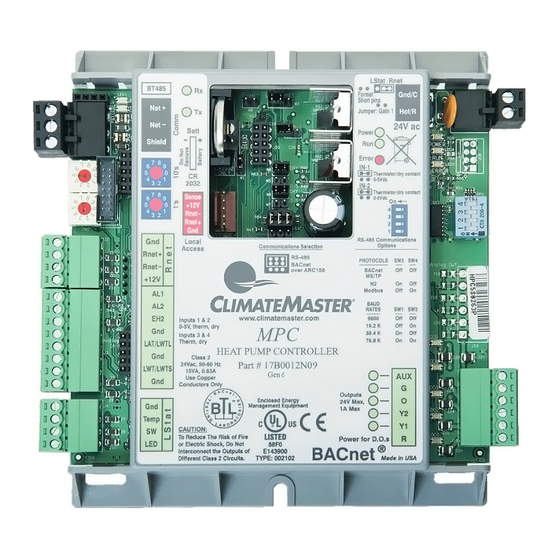
- Page 8 Communications Selection Protocol Configure When the Communications Selection jumper is in the The communications port on the MPC has MultiProtoCol “BACnet over ARC156” position, DIP switch selectors capability which means the MPC can be configured SW1, SW2, SW3, and SW4 are all disabled. When the to communicate via BACnet, Johnson Controls N2, or communications selection jumper is in the “BACnet over...
- Page 9 N2 Setup – N2 must be configured for RS-485 communications with a baud rate of 9600, using 8 data bits, no parity, and 1 stop bit. The MPC is always an N2 slave. Refer to Table 1 for setup. ModBus Setup – ModBus must be configured for RS-485 communications.
- Page 10 1. Lstat 2. RNet iGate Communication The RNet connection is at the upper left of the MPC and On units equiped with a DMX2 board, the iGate functions the LSat is at the lower left. Both are four to five wire are not available when the MPC is installed.
-
Page 11: Bacview6 Service Tool And Addressing
A large 4-line by 40-character backlit LCD display is provided for easy reading even in poor lighting conditions. The device also includes an alarm indicator light and audible warning. ClimateMaster recommends this service tool for sites over 25 units or units with the stand- alone application. - Page 12 “ones” digit, allowing for hardware- based address- ing of up to address 99. For example, if the module’s The Gen 4, 5 and 6 MPC allows the device instance address is three, set the tens switch to zero and the to be changed using the BACview6 service tool.
- Page 13 T H E S M A R T S O L U T I O N F O R E N E R G Y E F F I C I E N C Y MPC MultiProtoCol DDC Controls N o v e m b e r 1 9 , 2 0 1 8 BACview6 Service Tool and Addressing Addressing &...
- Page 14 Wire the Equipment Touch to the controller's RNet port. The RNet can have one Equipment Touch device and up to five RNet (ASW13) sensors. Note: The Equipment Touch RNet does not support RS Sensors. When prompted for password: ClimateMaster Password = 1111...
- Page 15 The Equipment Touch (Figure 12) is a touchscreen device with a 4.3 Inch color LCD Screen that is connected to an MPC GEN 7 Controller Unit. It will allow access to most all internal control/ status points, alarms that would normally require access to the system server (WebCNTL) to access.
- Page 16 T H E S M A R T S O L U T I O N F O R E N E R G Y E F F I C I E N C Y MPC MultiProtoCol DDC Controls N o v e m b e r 1 9 , 2 0 1 8 Equipment Touch Mounting Details 7.
-
Page 17: Mpc Led Codes
MPC LED Codes Digital Output LEDs The MPC Controller has the following LEDs: There are 5 digital outputs on the MPC. One output Power - indicates when power is on. (AUX) can be custom configured to control an external Run - blinks when the processor is running. -
Page 18: Mpc Sequence Of Operation
ECM, then the fan is energized only during a call for • Make sure the MPC wiring is correct. Make sure heating or cooling. "Auto" mode is the default mode of all color codes match and that no wire strands are operation At 30% PID, the fan(G) energizes in Auto shorting over to other terminals. - Page 19 EH2 output to button. This should display the correct address and the EHZ input on the MPC. This is available through number of ZS Sensors that are attached to the MPC. BAS network points. A history counter will also keep Press the <Back>...
- Page 20 AV:33 be made from the Wall Sensor. Dirty Filter Reset BV:7 Unchecked The MPC will default to RNet Sensors. If you have Dirty Filter Interval AV:30 1500 LSTAT Sensor types you will need to set jumper W3 Dirty Filter Mode...
- Page 21 Zone Temperature. You should be the MPC. You can remove the Y1, Y2 output wires to able to observe the Cool PID start increasing keep unit from going into Heat or Cool mode for this as the MPC is set to go into a Cooling cycle.
- Page 22 Cooling Mode YES: Go to step 3. Dirty Filter Mode Time Power down the MPC and wire up the BACview6 Load Balance Select Service Tool and ZS Sensor(s). Once these are EXT OCC/ Dirty FILT Sens installed, power MPC back up. The BACview6 should Archive Enable power up and display the “Main”...
- Page 23 RNet Sensor). You should be able observe the Cooling PID start increasing via to observe the Heat PID start increasing via WEBCNTL as the MPC is set to go into WEBCNTL (if it is being used). The MPC a Cooling cycle.
- Page 24 T H E S M A R T S O L U T I O N F O R E N E R G Y E F F I C I E N C Y MPC MultiProtoCol DDC Controls N o v e m b e r 1 9 , 2 0 1 8...
- Page 25 Actual heating setpoint based upon occupancy status, setpoint adjustment and metric conversion. Network setpoint for the cooling setpoint (Fahrenheit) in occupied mode. Fahrenheit network setpoint for multiple MPC's sharing the same space temperature sensor. Only for slave units when (BV:16) is"ON".
- Page 26 T H E S M A R T S O L U T I O N F O R E N E R G Y E F F I C I E N C Y MPC MultiProtoCol DDC Controls N o v e m b e r 1 9 , 2 0 1 8...
- Page 27 Indicates the number of Supply Fan operational Hours has exceeded the Dirty Filter Interval setting. Reset via Dirty Filter Reset (BV:7) Indicates there is no valid Room Sensor connected to the MPC Unit. Network Input to reset the C1 Cycle Counter (AV:20) back to Zero.
- Page 28 T H E S M A R T S O L U T I O N F O R E N E R G Y E F F I C I E N C Y MPC MultiProtoCol DDC Controls N o v e m b e r 1 9 , 2 0 1 8...
- Page 29 T H E S M A R T S O L U T I O N F O R E N E R G Y E F F I C I E N C Y MPC MultiProtoCol DDC Controls N o v e m b e r 1 9 , 2 0 1 8...
- Page 30 T H E S M A R T S O L U T I O N F O R E N E R G Y E F F I C I E N C Y MPC MultiProtoCol DDC Controls N o v e m b e r 1 9 , 2 0 1 8...
- Page 31 Network Input used to select between LSTAT (ASW06-08) wall sensors and communicating was sensors(ASW13-15). RNet should be "OFF" when using LSTAT Sensors and "ON" for all other configurations. The MPC board jumper W3 must be set to LSTAT for LSTAT sensors or RNet for RNet sensors.
- Page 32 T H E S M A R T S O L U T I O N F O R E N E R G Y E F F I C I E N C Y MPC MultiProtoCol DDC Controls N o v e m b e r 1 9 , 2 0 1 8...
- Page 33 T H E S M A R T S O L U T I O N F O R E N E R G Y E F F I C I E N C Y MPC MultiProtoCol DDC Controls N o v e m b e r 1 9 , 2 0 1 8...
- Page 34 T H E S M A R T S O L U T I O N F O R E N E R G Y E F F I C I E N C Y MPC MultiProtoCol DDC Controls N o v e m b e r 1 9 , 2 0 1 8...
-
Page 35: Mpc Feature Configuration
RNet Sensor Setup (Generation 7 only): The Gen7 Alarm Relay AUX output turns “ON” anytime MPC is capable of averaging up to 5 ZS Sensors Output ALARM is True. together over the RNet link. Use one ASW15 and up Reheat ICM &... - Page 36 9. Test Mode (All Generations): Test Mode is used compressor with the least runtime becomes to test the output functions of the MPC unit This the stage 1 compressor while the high time configuration will only remain active for 30 Minutes.
- Page 37 W8. Reset the Rotary switches c: Slave CLSP (AV10) to 0,2.. 7. Power the MPC back up and it should be ready d: Occupied Mode(BV12) 3: Map the Master Points to the Slave points. to run with the restored Factory programming.
-
Page 38: Generation 4 Water-To-Water Points Matrix
T H E S M A R T S O L U T I O N F O R E N E R G Y E F F I C I E N C Y MPC MultiProtoCol DDC Controls N o v e m b e r 1 9 , 2 0 1 8... - Page 39 Network setpoint for the cooling setpoint (Fahrenheit) in occupied mode. Fahrenheit network setpoint for multiple MPC's sharing the same space temperature sensor. Ony for slave units when M/S Switch (BV:16) is"ON". Slave Cooling Differential Deadband. Active only when M/S Switch (BV:16) is"ON".
- Page 40 T H E S M A R T S O L U T I O N F O R E N E R G Y E F F I C I E N C Y MPC MultiProtoCol DDC Controls N o v e m b e r 1 9 , 2 0 1 8...
- Page 41 T H E S M A R T S O L U T I O N F O R E N E R G Y E F F I C I E N C Y MPC MultiProtoCol DDC Controls N o v e m b e r 1 9 , 2 0 1 8 Description Network input for the actual Celsius Heating Setpointwhen used as a slave unit.
-
Page 42: Mpc Wall Sensors
The three different types of ASW wall sensors feature easy to use analog to digital connections on the MPC. With only 4 to 5 wire connections, the field technician can easily troubleshoot the ASW to determine if it is operating properly. - Page 43 T H E S M A R T S O L U T I O N F O R E N E R G Y E F F I C I E N C Y MPC MultiProtoCol DDC Controls N o v e m b e r 1 9 , 2 0 1 8 ASW 13,14,15 Wall Sensors (RNet Sensors) - For use with MPC ASW13 ASW14...
- Page 44 T H E S M A R T S O L U T I O N F O R E N E R G Y E F F I C I E N C Y MPC MultiProtoCol DDC Controls N o v e m b e r 1 9 , 2 0 1 8...
- Page 45 LSTAT Wall Sensors The three different types of LSTAT ASW wall sensors feature easy to use analog to digital connections on the MPC. With only 4 to 5 wire connections, the field technician can easily troubleshoot to the ASW to determine if it is operating properly.
- Page 46 3. Pull the RNet communication cable through the large rectangle in the backplate. Figure 18: Climatemaster recommends that you use the following RNet wiring scheme: Connect this wire... To this terminal... +12V...
- Page 47 1 second. of override time. The maximum override time will always c) The MPC will interpret the button a manual reset and be 180 minutes. the MPC will reset the heat pump.
- Page 48 6. At this point you can use the Tablet or Phone to This section covers the installation and setup of the set up and monitor the MPC just as if it had an Android Application from OEMCntl that allows an Equipment Touch Screen attached.
- Page 49 BMS but not at the CXM? A. Yes using the RNet sensors. Up to five sensors may A. The jumper IN1 on the MPC is set to 0-5Vdc instead be daisy chained. One ASW15 and up to 4 ASW13 of dry.
- Page 50 There are three Icons that are present on every screen, MPC file. Home, Back and Information. Clicking the Home Screen 3. MPC Setup/Status- Navigates to the screen allowing will return the user to this screen which is the top of the access to all user setup/status screens.
- Page 51 Equipment Touch Manual - Screen Descriptions Maintenance Screen The Maintenance Screen is used to monitor normal operation of the MPC unit and contain various status points. Using the Home Icon or Home button will return the user to the Home Screen. For information on the Maintenance screen the Help Button will provide help on the meaning and use of the Icons used in the Screen.
- Page 52 8. Heat/Cool Contro l - Provides access to the control points and status screen related to controlling Heating and Cooling function. (Control/ Status). 9. MPC Alarms - Provides access to the MPC Alarm Status Screen (Status Only). 10. MPC Faults - Provides Access to the MPC Fault Status Screen (Status Only).
- Page 53 T H E S M A R T S O L U T I O N F O R E N E R G Y E F F I C I E N C Y MPC MultiProtoCol DDC Controls N o v e m b e r 1 9 , 2 0 1 8...
- Page 54 T H E S M A R T S O L U T I O N F O R E N E R G Y E F F I C I E N C Y MPC MultiProtoCol DDC Controls N o v e m b e r 1 9 , 2 0 1 8...
- Page 55 T H E S M A R T S O L U T I O N F O R E N E R G Y E F F I C I E N C Y MPC MultiProtoCol DDC Controls N o v e m b e r 1 9 , 2 0 1 8...
- Page 56 T H E S M A R T S O L U T I O N F O R E N E R G Y E F F I C I E N C Y MPC MultiProtoCol DDC Controls N o v e m b e r 1 9 , 2 0 1 8...
- Page 57 T H E S M A R T S O L U T I O N F O R E N E R G Y E F F I C I E N C Y MPC MultiProtoCol DDC Controls N o v e m b e r 1 9 , 2 0 1 8...
- Page 58 AUX output in Relative Humidity mode. When Off the Aux output goes on when the Trip Point is exceeded and the MPC is in Occupancy Mode. When It is ON the AUX output will respond anytime the setpoint is exceeded regardless of...
- Page 59 T H E S M A R T S O L U T I O N F O R E N E R G Y E F F I C I E N C Y MPC MultiProtoCol DDC Controls N o v e m b e r 1 9 , 2 0 1 8...
- Page 60 T H E S M A R T S O L U T I O N F O R E N E R G Y E F F I C I E N C Y MPC MultiProtoCol DDC Controls N o v e m b e r 1 9 , 2 0 1 8...
- Page 61 Hour period. Figure 45: 10. TEST Mode Alarm- This alarm is present when the MPC is put into test mode and stays in test mode longer than 1 hour 11. CO2 Alarm- Alarm triggers when CO2 levels exceed the setpoint.
- Page 62 Leaving Water Temperature status. These points do faults. For more information on these faults, please refer not affect control of the MPC unit but instead are for to the DXM2 Software specification. reporting purposes for the BMS and are available via analog outputs 1 and 2.
- Page 63 T H E S M A R T S O L U T I O N F O R E N E R G Y E F F I C I E N C Y MPC MultiProtoCol DDC Controls N o v e m b e r 1 9 , 2 0 1 8...
- Page 64 T H E S M A R T S O L U T I O N F O R E N E R G Y E F F I C I E N C Y MPC MultiProtoCol DDC Controls N o v e m b e r 1 9 , 2 0 1 8...
- Page 65 The ALARM will reset automatically anytime a sensor is plugged in after the ALARM has triggered. To configure the Equipment Touch for RNet sensors. 1. RNet Mode- allows the MPC to function with LS Navigate to the following menu (RNet (ZS) Sensor Setup) Sensors when RNet is OFF.
- Page 66 Figure 57: This should take to the RNet Active screen which allows you to see if a individual sensor is present. This is all that is required to setup for running RNet sensors with the 7 Version of the MPC.
- Page 67 This should allow the Equipment Touch to send Temp Because of this there are separate procedures for and Humidity Data the MPC. You can verify it is in fact reverting to these archives. functioning by disconnecting and other sensors RNet/...
- Page 68 Figure 60: When the Archive Now Box is checked the MPC will archive the current modified program including all control settings and display the current archive number, Month, Day and Year of the Archive will be displayed. See above 3.
- Page 69 T H E S M A R T S O L U T I O N F O R E N E R G Y E F F I C I E N C Y MPC MultiProtoCol DDC Controls N o v e m b e r 1 9 , 2 0 1 8...
- Page 70 T H E S M A R T S O L U T I O N F O R E N E R G Y E F F I C I E N C Y MPC MultiProtoCol DDC Controls N o v e m b e r 1 9 , 2 0 1 8...
- Page 71 T H E S M A R T S O L U T I O N F O R E N E R G Y E F F I C I E N C Y MPC MultiProtoCol DDC Controls N o v e m b e r 1 9 , 2 0 1 8...
-
Page 72: Revision History
Revision History Date: Item: Action: 11/19/18 Added Equipment Touch/, Generation 7 3/7/17 Misc. Edits 07/14/16 Logo Updated 05/31/16 First Published 7300 S.W. 44th Street *97B0031N01* Oklahoma City, OK 73179 Phone: 405-745-6000 97B0031N01 Fax: 405-745-605 We work continually to improve our products. As a result, the design and specifications of each product at the time of order may be changed without notice and may not be as described herein.
Need help?
Do you have a question about the MPC and is the answer not in the manual?
Questions and answers