Advertisement
Advertisement
Table of Contents

Related Manuals for Sehan Electools F

Summary of Contents for Sehan Electools F
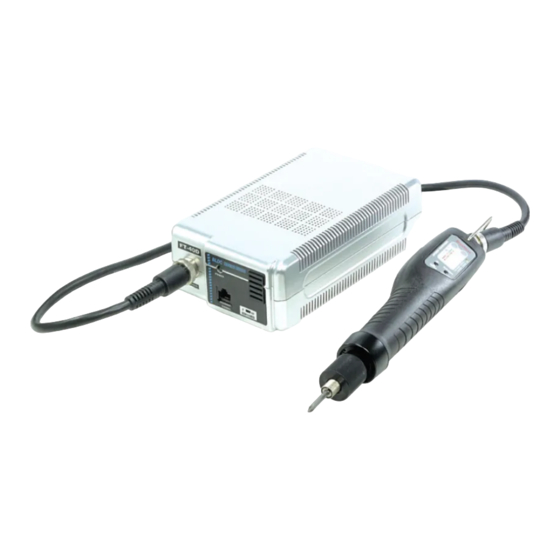
- Page 1 - March 31, 2014 OPERATION MANUAL F, LF, NF Screwdrivers Mini F...
-
Page 2: General Safety Rules
1. GENERAL SAFETY RULES WARNING! Read and understand all instructions. Failure to follow all instructions listed below, may result in electric shock, fire and/or serious personal injury SAVE THIS INSTRUCTIONS 1.1 Work Area Keep your work area clean and well lit. Cluttered benches and dark areas invite accidents. Do not operate power tools in explosive atmospheres, such as in the presence of flammable liquids, gases, or dust. -
Page 3: Specific Safety Rules
Use safety equipment. Always wear eye protection. Dust mask, non-skid safety shoes, hard hat, or hearing protection must be used for appropriate conditions. 1.4 Tool use and Care Use clamps or other practical way to secure and support the workplace to a stable platform. - Page 4 3. Electric specification Items Power controller Screwdriver F060, F080, F120 Model FT-40D NF150, NF220, NF350, NF450, NF150P,NF220P,NF350P,NF450P Input 110 / 230VAC (selectable) DC40V Output 30/40VDC ( selectable ) Rated power 2.5A 95W Maximum output current Intermittent operation 10s On / 30s Off Safety certification CE, NRTL(C+U), KC Detailed specification...
- Page 5 6. Pin configuration of output 1 : DC (+) 2 : Limit (Torque up) 3 : Ground 4 : Start 5 : DC (-) 6 : Driver Lock or Remote start ( for "A" option driver ) View of controller View of cable side Caution : Do not connect the others except the listed screwdrivers.
- Page 6 9. Connections Ground FT-40D F series NF series Signal OUT Start Stop Signal IN Driver LOCK or Remote start U-3B interface converter SCOUT II Signal OUT Signal OUT Cycle END Signal IN Buzzer Signal IN SCOUT V2.0 or later Cycle START...
- Page 7 10. Interface with FT-40D controller 10-1. Connector and cables ■ Connection Cable (801120) FT-40D SCOUT 1. Orange ■ Signal Cable (801121) 2. White+Orange stripe 3. Blue RJ-45 4. White+Blue stripe Modular Jack 5. Green on FT-40D 1.5M 6. White+Green stripe 7.
- Page 8 10-3. Timing chart of Start / Stop signal Start Stop 0.15 sec 10-4. Dimensional drawing - 7 -...
- Page 9 10-5. Interface converter U-3B ( Option ) Interface converter convert the electronic signal by opto coupler to opposite direction as below. Also it provide additional dry contact signals in both Normal Closed and Normal Open by the built-in relay Interface converter (ECA5914) U-3B Size...
- Page 10 ■ U-3B interface converter I/O details 1 Opto-coupler port U-3B 12-24VDC(+) 10mA TORQUE UP PC817 START (motor run) 12V return PC817 DRIVER LOCK or REMOTE START ("A" option driver) 2 & 3 Relay N.C & N.O port U-3B Normal Closed TORQUE UP Normal Open Normal Closed...
-
Page 11: Screwdriver Specification
No load speed Weight Torque Speed(RPM) Weight Type Model Start Bit size Voltage Model Screw Start Controller (rpm) (Kg) (Kgf.cm) Kgf.cm Mini F series NF150 M2.6~M4 3~15 1700 F035 0.3~3.5 300~1,100 Speed LEVER 0.24 DC30V control NF220 M3~M5 F045 Lever 6~22 0.5~4.5... - Page 12 12. Screwdriver Dimensions ■ Mini F series Ø30 Ø32 Ø31 Ø35.4 ■ Mini F series Ø32.8 ■ Mini F series Ø38.4 Ø32 Ø33 ■ Mini F series Ø41.6 Ø34.3 - 11 -...
-
Page 13: Torque Curve (At No Load Max. Speed)
13. Torque curve (at No load Max. speed) LF120, LF120P LF180, LF180P Gold Silver scale scale Gold (dia2.0) : 4 - 10 Kgf.cm Silver (dia2.1) : 4 - 15 Kgf.cm NF150, NF220, NF350, NF450 LF250, LF250P Black scale Black (dia2.2) : 7 - 20 Kgf.cm - 12 -... -
Page 14: Panel Of Each Model
14. Panel of each model ■ Standard ■ Soft start & Double hit ( + option ) ■ Angle control & Auto reverse ( T option ) 15. Alarm display by LED Alarm Description Reset ●●↔●● 1 Over Voltage (over 44V) Green &... -
Page 15: Operation
1) Keep pressing the Speed button for 2 second to visit to PROGRAM mode. Then two LED lights will display the set speed. 2) Select "Reverse" of F/R switch for increasing speed. or select "Forward" of F/R switch for increasing speed. 3) Press "Speed" button and select the target speed. - Page 16 1/4 to 15 turns 0.2 to 3 sec 1/4 to 15 turns delay - Screwdriver stops Immediately when the lever is released in any sequence. - Sliding F/R switch works for ■ Operating (Work) mode ① Rotating direction (FOR-REV) ■...
- Page 17 ① Keep the first Run button pressed over 2 sec. for angle setting. Then press one by one for the desired rotating angle ② Select the R position of F/R switch for increasing set angle or F position for decreasing set angle ③...
- Page 18 ① Keep the both first Run & stop time buttons pressed over 2 sec. for unlock. Then click one by one for the desired rotating speed. ② Select the R position of F/R switch for increasing speed or F position for decreasing speed ③...
- Page 19 ■ Application Example first stop Auto Applications with different HOLD Reverse sequence in a cycle Angle Time Angle Normal Normal screwdriver screwdriver It stops at the set torque Angle ON(1) It stops at set angle(1) control It stops at set angle(1) and Tapper ON(3) waits for set time(2), and makes...
Need help?
Do you have a question about the F and is the answer not in the manual?
Questions and answers