
Related Manuals for HGST Ultrastar Serv24-HA


Summary of Contents for HGST Ultrastar Serv24-HA
- Page 1 User Guide Ultrastar Serv24-HA P2522 Version 1.2 August 2018 1ET1089 ™ Long Live Data | www.hgst.com...
-
Page 2: Table Of Contents
Contents User Guide Contents Revision History....................7 Points of Contact.....................8 Copyright......................9 Supported SKUs...................10 Chapter 1 Ultrastar Serv24-HA Overview..........11 1.1 Ultrastar Serv24-HA Description............11 Block Diagrams................12 1.3 Ultrastar Serv24-HA Specification Summary........14 1.4 System Architecture Overview............16 Ultrastar Serv24-HA Layout.............16 Ultrastar Serv24-HA Rack Requirements........16 1.7 List of Replaceable Components.............17 LEDs....................18... - Page 3 Contents User Guide 2.3 PSU Description................25 2.3.1 PSU Specifications...............25 2.3.2 PSU Layout..................26 2.4 Drive Description................27 2.4.1 Drive Specifications..............27 2.4.2 Drive Layout.................28 2.5 Drive Blank Assembly Description...........29 2.5.1 Drive Blank Assembly Specifications...........29 2.5.2 Drive Blank Assembly Layout............30 Fan Description................31 2.6.1 Fan Specification................31 2.6.2 Fan Layout..................32 2.7 Compute Canister Description............32...
- Page 4 Rails Replacement.................78 3.11 Chassis Replacement..............88 3.12 Compute Canister Replacement..........105 3.13 (Optional) Battery Backup Replacement........117 Chapter 4 System Management............124 4.1 Managing Ultrastar Serv24-HA............124 4.2 Downloading Firmware from the Support Portal......124 Web UI Overview................127 4.3.1 Web UI Supported Browsers............129 4.3.2 Creating a New User in Web UI..........129 4.3.3...
- Page 5 Contents User Guide Chapter 5 Disclaimers................159 Safety Compliance.................159 5.2 Restricted Access Location............159 Regulatory Statement..............159 5.4 Electromagnetic Compatibility (EMC) Class A Compliance ..160 Country Certifications..............160 Chapter 6 Safety..................162 Electrostatic Discharge..............162 6.2 Optimizing Location................162 Power Connections................162 6.4 Power Cords...................163 Replaceable Batteries..............163 Rackmountable Systems...............163 6.7 Safety and Service.................164 6.8 Safety Warnings and Cautions............164 Chapter 7 Regulatory Statements............165...
- Page 6 Contents User Guide CFUFlash Commands..............174 CFUFlash Options.................174 A.7 CFUFlash Medium.................175 Appendix B System Operations Appendices..........176 ESD....................176 B.2 System Cooling................176 Power Requirements..............176 B.4 Host Connectivity................177 Appendix C Compatibility.................178 Compatible Operating Systems List..........178 C.2 Compatible Parts List..............178...
-
Page 7: Revision History
Revision History User Guide Revision History Date Revision Comment February 2018 Revision 1.0 Initial Release April 2018 Revision 1.1 Added the Battery Backup on page 35 section to the Component Overviews on page 22 August 2018 Revision 1.2 Updated the following: •... -
Page 8: Points Of Contact
Points of Contact User Guide Points of Contact For further assistance with an HGST product, contact Global Service and Support. Please be prepared to provide the following information: Serial Number (S/N), product name, model number, and a brief description of the issue. -
Page 9: Copyright
Long Live Data is a trademark of HGST, Inc. and its affiliates in the United States and/or other countries. HGST trademarks are authorized for use in countries and jurisdictions in which HGST has the right to use, market and advertise the brands. -
Page 10: Supported Skus
Supported SKUs User Guide Supported SKUs The following table lists the versions of this HGST product that are supported by this document. SKUs 1ES1029 1ES1037 1ES1030 1ES1038 1ES1000 1ES1039 1ES1031 1ES1001 1ES1032 1ES1040 1ES1003 1ES1041 1ES0405 1ES1042 1ES1033 1ES1043 1ES1034... -
Page 11: Chapter 1 Ultrastar Serv24-Ha Overview
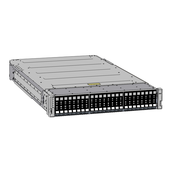
The Ultrastar Serv24-HA is a high availability 2U, 24 bay, dual node storage server. The maximum data storage capacity of the Ultrastar Serv24-HA is 184.32 TB using HGST Ultrastar SN200 drives. For a full list of compatible drives and total storage capacities, see the List of Compatible Drives on page 20. -
Page 12: Block Diagrams
Ultrastar Serv24-HA Overview User Guide Block Diagrams 1.2 Block Diagrams Figure 2: Enclosure System Block Diagram Figure 3: NVMe Canister Block Diagram... - Page 13 Ultrastar Serv24-HA Overview User Guide Block Diagrams Figure 4: Processor Block Diagram...
-
Page 14: Ultrastar Serv24-Ha Specification Summary
Ultrastar Serv24-HA Overview User Guide Ultrastar Serv24-HA Specification Summary Figure 5: PCIe Switch (PM8546) Block Diagram 1.3 Ultrastar Serv24-HA Specification Summary Table 1: Environmental Specification Summary Specification Non-Operational Operational Temperature -40°C to 60°C 5°C to 35°C Temperature Gradient 30°C per hour max... - Page 15 Ultrastar Serv24-HA Overview User Guide Ultrastar Serv24-HA Specification Summary Specification Non-Operational Operational Temperature De-rating 1°C per 300m above 12000m 1°C per 300m above 950m Relative Humidity 8-95% Non-Condensing 8-85% Non-Condensing Relative Humidity Gradient 30% per hour maximum 30% per hour maximum...
-
Page 16: System Architecture Overview
System Architecture Overview 1.4 System Architecture Overview The Ultrastar Serv24-HA consists of a main chassis that is populated with up to 24 NVMe drives, two Compute Canisters, and redundant 1800W PSUs. Each Compute Canister contains physical connections for dual CPUs, a platform controller hub (PCH), 24 DIMM sockets, three PCIe generation 3 slots (one slot open for user expansion), a system BMC, and a removable Trusted Platform Module (TPM). -
Page 17: List Of Replaceable Components
Ultrastar Serv24-HA Overview User Guide List of Replaceable Components 2U of rackspace, and it should be installed into the rack at the lowest possible U height to keep the load on the rack balanced. 1.7 List of Replaceable Components Table 6: List of Replaceable Components... -
Page 18: Leds
Ultrastar Serv24-HA Overview User Guide LEDs 1.8 LEDs 1.8.1 Chassis LEDs Figure 7: Chassis LEDs Table 7: Chassis LEDs Number Action Power • Off: Power off • Green: Power on Identify • Off: Chassis is not being identified • Blue: Chassis is being identified Fault •... -
Page 19: Psu Led
Ultrastar Serv24-HA Overview User Guide LEDs 1.8.2 PSU LED Figure 8: PSU LED Table 8: PSU LED Number Action Fault • Off: PSU not powered on • Green: Powered on, DC output OK • Amber: Fault, failure, or AC disconnection on PSU 1.8.3... -
Page 20: Input/Output
Ultrastar Serv24-HA Overview User Guide Input/Output 1.9 Input/Output 1.9.1 Rear I/O Ports and Features Figure 10: Rear I/O Ports and Features Table 10: Rear I/O Ports and Features Number Port PSU (x2) USB 3.0 USB 3.0 1 GbE for IPMI (RJ45) - Page 21 Ultrastar Serv24-HA Overview User Guide 1.10 List of Compatible Drives Drive Capacity Part Number HGST Ultrastar SN200 3.84 TB 1EX1040 RI-1DW/D SE HGST Ultrastar SN200 7.68 TB 1EX1041 RI-1DW/D SE SanDisk X400 SSD M.2 2280 256 GB 1EX1026 Boot Drive...
-
Page 22: Chapter 2 Component Overviews
The chassis is the primary housing that contains and connects all of the system components that comprise the Ultrastar Serv24-HA. The chassis is contains the drive bay, located at the front, which houses all of the system data storage drives. The rear of the chassis contains PSU bays and two Compute Canisters. The major system components such as the fan modules, CPUs, memory, and M.2 Boot Drives are all contained... -
Page 23: Chassis Layout
The PIB Canister contains a connector on the PSU end that attaches to the PIB and finishes at the other end in a card edge connection that fits into a midplane connector. The Ultrastar Serv24-HA contains two PIB Canisters installed before the redundant PSUs. -
Page 24: Pib Canister Specifications
Component Overviews User Guide PIB Canister Description 2.2.1 PIB Canister Specifications Table 14: Chassis Specification Summary Specification Value Dimensions W: 40.2 mm x L: 715.46 mm x H: 78.1 mm / W: 1.58in. x L: 28.1in. x H: 3.06in. Part Number 1EX1054 Hot Swappable? Weight... -
Page 25: Psu Description
Handle 2.3 PSU Description Figure 15: PSU Description Ultrastar Serv24-HA contains two redundant 1800W Power Supply Units (PSU). Each PSU requires an input ™ voltage of between 200-240VAC. The PSUs are 80 Plus Platinum certified, and utilize C14 power cable receptacles. -
Page 26: Psu Layout
Component Overviews User Guide PSU Description 2.3.2 PSU Layout Figure 16: PSU Layout Table 17: PSU Layout Number Feature Latch Release Lever Power Receptacle Handle Connector... -
Page 27: Drive Description
2.4 Drive Description Figure 17: Drive Description The Ultrastar Serv24-HA contains up to 24 Non-Volatile Memory Express (NVMe) drives preinstalled into the chassis. The drive module is comprised of two parts: the storage drive and the drive carrier. The carrier attaches to the exterior of the data storage drive and caddies the drive into the system. -
Page 28: Drive Layout
Component Overviews User Guide Drive Description 2.4.2 Drive Layout Figure 18: Drive Layout Table 19: Drive Layout Number Feature Drive Drive Carrier Carrier Handle Latch Release Button LEDs... -
Page 29: Drive Blank Assembly Description
Component Overviews User Guide Drive Blank Assembly Description 2.5 Drive Blank Assembly Description Figure 19: Drive Description The Drive Blank Assembly is designed to maintain the proper airflow for a partially populated enclosure. The Drive Blank Assembly contains many of the same features that a typical Drive Assembly has to ensure that the enclosure has the ability to run efficiently. -
Page 30: Drive Blank Assembly Layout
Component Overviews User Guide Drive Blank Assembly Description 2.5.2 Drive Blank Assembly Layout Figure 20: Drive Blank Layout Table 21: Drive Blank Assembly Layout Number Feature Drive Blank Drive Carrier Latch Release Button Drive Carrier Latch... -
Page 31: Fan Description
2.6 Fan Description Figure 21: Fan Description The Fan Modules are toolless internal fans that provide the primary cooling for the Ultrastar Serv24-HA. The fan are installed inside the compute canister in close proximity to the compute canister components to provide efficient cooling to all of the drives. -
Page 32: Fan Layout
Fan Module 2.7 Compute Canister Description Figure 23: Compute Canister Description The chassis contains redundant Compute Canisters that each house and connect system components that comprise the Ultrastar Serv24-HA. The major system components such as the fan modules, CPUs, DIMMs,... -
Page 33: Compute Canister Specification
Component Overviews User Guide Compute Canister Description Battery Backup, and M.2 Boot Drives are all contained in each of the Compute Canisters. The redundancy of the Compute Canisters is designed so that the system can run on one canister in the event that the other canister fails. -
Page 34: Rails Description
Figure 25: Rails Description The Ultrastar Serv24-HA is attached to the rack using two rack mounted rails that allow for the computer canisters to be pulled out of the rear for servicing. The rails contain a rack ear locking mechanism on either side to secure the enclosure in the rack during basic servicing procedures. -
Page 35: Battery Backup
Figure 27: Battery Backup Description The Ultrastar Serv24-HA has the option to add a battery backup module to each of the Compute Canisters. The battery backup contains a sheet metal case that encloses and protects the battery cells from damage. -
Page 36: Chapter 3 Part Replacement
Part Replacement User Guide Drive Assembly Replacement Chapter 3 Part Replacement 3.1 Drive Assembly Replacement Table 29: Replacement Procedure Info Required Tools # of People Required Time Required None 3 minutes 1. Locate the failed drive by identifying the illuminated amber LED on the drive carrier. 2. -
Page 37: Drive Blank Assembly Replacement
Part Replacement User Guide Drive Blank Assembly Replacement b) With the drive carrier button on top, slowly slide the drive into the open drive slot using the drive carrier release until the drive release engages. Figure 30: Drive Assembly Installation c) Seat the drive by pressing the lever into the drive carrier. - Page 38 Part Replacement User Guide Drive Blank Assembly Replacement a) Release the drive blank assembly by pressing the button on the drive blank carrier and lower the carrier release until it stops. Figure 32: Drive Blank Carrier Release Press b) Pull the drive blank assembly out of the drive slot. Figure 33: Uninstall Drive Blank Assembly 3.
-
Page 39: Dimm Replacement
Part Replacement User Guide DIMM Replacement 3.3 DIMM Replacement Table 31: Replacement Procedure Info Required Tools # of People Required Time Required None 7 minutes 1. Identify the failed DIMM. a) Open a browser and browse to the BMC IP Address of the Compute Canister. The Web UI will appear. - Page 40 Part Replacement User Guide DIMM Replacement b) Unlatch the Compute Canister by pulling both of the handles out of the chassis. Figure 37: Unlatching the Compute Canister c) Remove the Compute Canister by grasping the edges of the canister and pulling it clear of the enclosure. Figure 38: Uninstalling the Compute Canister 3.
- Page 41 Part Replacement User Guide DIMM Replacement a) Pull connector tabs outward with even pressure until the DIMM pops out of the connector. Figure 39: Unlocking the DIMM b) Carefully remove the DIMM from the slot. Figure 40: Uninstalling the DIMM c) Take note of the location of each DIMM as it is removed to ensure that it is installed into the correct location of the replacement Compute Canister.
- Page 42 Part Replacement User Guide DIMM Replacement 6. Install the Compute Canister cover. a) Align the cover over the Compute Canister and slide towards the front of the Compute Canister. b) Verify the locks on the cover have engaged and the cover is secure. 7.
-
Page 43: Cpu And Heat Sink Module Replacement
Part Replacement User Guide CPU and Heat Sink Module Replacement The Web UI will appear. Figure 44: Web UI b) In the Web UI, click Dashboard. The Dashboard Control Panel page will appear. Figure 45: Dashboard Control Panel c) Review the Dashboard Control Panel to identify that there are no failures reported. 3.4 CPU and Heat Sink Module Replacement Table 32: Replacement Procedure Info Required Tools... - Page 44 Part Replacement User Guide CPU and Heat Sink Module Replacement The Web UI will appear. Figure 46: Web UI b) In the Web UI, click Dashboard. The Dashboard Control Panel page will appear. Figure 47: Dashboard Control Panel c) Review the Dashboard Control Panel to identify the failed CPU. Uninstall the Compute Canister from the enclosure.
- Page 45 Part Replacement User Guide CPU and Heat Sink Module Replacement b) Unlatch the Compute Canister by pulling both of the handles out of the chassis. Figure 48: Unlatching the Compute Canister c) Remove the Compute Canister by grasping the edges of the canister and pulling it clear of the enclosure.
- Page 46 Part Replacement User Guide CPU and Heat Sink Module Replacement b) The Heat Sink must be removed by loosening the Torx T30 screws in a specific order. Use the following diagram to determine the specific order. Figure 50: Heat Sink Removal Order...
- Page 47 Part Replacement User Guide CPU and Heat Sink Module Replacement c) Slide the Heat Sink clear of the socket alignment pins. Figure 51: Uninstall CPU Identify the location of the first heat sink containing the CPU on the new enclosure. Install the CPU and Heat Sink module.
- Page 48 Part Replacement User Guide CPU and Heat Sink Module Replacement Note: The Heat Sink screws must be tightened to a torque setting of 12in.-lbs. Do not over-tighten. Over-tightening may cause damage to the parts. Figure 52: Install CPU Figure 53: Heat Sink Installation Order...
- Page 49 Part Replacement User Guide CPU and Heat Sink Module Replacement Repeat the previous step to install the remaining heat sink containing the CPU. Install the Compute Canister cover. a) Align the cover over the Compute Canister and slide towards the front of the Compute Canister. b) Verify the locks on the cover have engaged and the cover is secure.
- Page 50 Part Replacement User Guide CPU and Heat Sink Module Replacement b) Carefully slide the Compute Canister into the slot with both latch handles in the open position until the latch handles begin to engage. Figure 54: Installing the Compute Canister c) Rotate the latch handles into the enclosure until the are fully engaged.
-
Page 51: Heat Sink Replacement
Part Replacement User Guide Heat Sink Replacement The Web UI will appear. Figure 56: Web UI b) In the Web UI, click Dashboard. The Dashboard Control Panel page will appear. Figure 57: Dashboard Control Panel c) Review the Dashboard Control Panel to identify that there are no failures reported. 3.5 Heat Sink Replacement Table 33: Replacement Procedure Info Required Tools... - Page 52 Part Replacement User Guide Heat Sink Replacement The Web UI will appear. Figure 58: Web UI b) In the Web UI, click Dashboard. The Dashboard Control Panel page will appear. Figure 59: Dashboard Control Panel c) Review the Dashboard Control Panel to identify the failed Heat Sink. Uninstall the Compute Canister from the enclosure.
- Page 53 Part Replacement User Guide Heat Sink Replacement b) Unlatch the Compute Canister by pulling both of the handles out of the chassis. Figure 60: Unlatching the Compute Canister c) Remove the Compute Canister by grasping the edges of the canister and pulling it clear of the enclosure.
- Page 54 Part Replacement User Guide Heat Sink Replacement b) The Heat Sink must be removed by loosening the Torx T30 screws in a specific order. Use the following diagram to determine the specific order. Figure 62: Heat Sink Removal Order...
- Page 55 Part Replacement User Guide Heat Sink Replacement c) Slide the Heat Sink clear of the socket alignment pins. Figure 63: Uninstall CPU Remove the CPU from the Heat Sink. a) Locate the seam that connects the CPU and Heat Sink. Figure 64: Removing the CPU from the Heat Sink with a Spudger b) Insert the edge of a plastic spudger in between the CPU and Heat Sink and carefully pry the two components apart.
- Page 56 Part Replacement User Guide Heat Sink Replacement Install the Heat Sink onto the CPU. a) Clean the thermal compound from the top of the CPU using isopropyl alcohol and lint-free wipes. Ensure that the CPU is residue free and dry before installing the replacement Heat Sink. b) Align the gold triangle on the CPU with the triangle on CPU retainer and snap the CPU into the plastic CPU retainer.
- Page 57 Part Replacement User Guide Heat Sink Replacement Identify the location of the first heat sink containing the CPU on the new enclosure. Install the CPU and Heat Sink module. a) Locate the socket alignment pin on the baseboard and the alignment hole on the Heat Sink. b) Carefully place the CPU and Heat Sink module in position on the socket alignment pins.
- Page 58 Part Replacement User Guide Heat Sink Replacement Note: The Heat Sink screws must be tightened to a torque setting of 12in.-lbs. Do not over-tighten. Over-tightening may cause damage to the parts. Figure 67: Install CPU Figure 68: Heat Sink Installation Order...
- Page 59 Part Replacement User Guide Heat Sink Replacement Repeat the previous step to install the remaining heat sink containing the CPU. 10. Install the Compute Canister cover. a) Align the cover over the Compute Canister and slide towards the front of the Compute Canister. b) Verify the locks on the cover have engaged and the cover is secure.
- Page 60 Part Replacement User Guide Heat Sink Replacement b) Carefully slide the Compute Canister into the slot with both latch handles in the open position until the latch handles begin to engage. Figure 69: Installing the Compute Canister c) Rotate the latch handles into the enclosure until the are fully engaged. Figure 70: Latching the Compute Canister 12.
-
Page 61: Boot Drive Replacement
Part Replacement User Guide M.2 Boot Drive Replacement The Web UI will appear. Figure 71: Web UI b) In the Web UI, click Dashboard. The Dashboard Control Panel page will appear. Figure 72: Dashboard Control Panel c) Review the Dashboard Control Panel to identify that there are no failures reported. 3.6 M.2 Boot Drive Replacement Table 34: Replacement Procedure Info Required Tools... - Page 62 Part Replacement User Guide M.2 Boot Drive Replacement 1. Identify the failed boot drive. a) Open a browser and browse to the BMC IP Address of the Compute Canister. The Web UI will appear. Figure 73: Web UI b) In the Web UI, click Dashboard. The Dashboard Control Panel page will appear.
- Page 63 Part Replacement User Guide M.2 Boot Drive Replacement b) Unlatch the Compute Canister by pulling both of the handles out of the chassis. Figure 75: Unlatching the Compute Canister c) Remove the Compute Canister by grasping the edges of the canister and pulling it clear of the enclosure. Figure 76: Uninstalling the Compute Canister 3.
- Page 64 Part Replacement User Guide M.2 Boot Drive Replacement b) Remove the drive from the drive slot by pulling it out of the connector. Figure 77: M.2 Boot Drive Removal 5. Identify the location of the first M.2 boot drive on the replacement Compute Canister. 6.
- Page 65 Part Replacement User Guide M.2 Boot Drive Replacement b) Carefully slide the Compute Canister into the slot with both latch handles in the open position until the latch handles begin to engage. Figure 79: Installing the Compute Canister c) Rotate the latch handles into the enclosure until the are fully engaged. Figure 80: Latching the Compute Canister 9.
-
Page 66: Nic Replacement
Part Replacement User Guide NIC Replacement The Web UI will appear. Figure 81: Web UI b) In the Web UI, click Dashboard. The Dashboard Control Panel page will appear. Figure 82: Dashboard Control Panel c) Review the Dashboard Control Panel to identify that there are no failures reported. 3.7 NIC Replacement Table 35: Replacement Procedure Info Required Tools... - Page 67 Part Replacement User Guide NIC Replacement The Web UI will appear. Figure 83: Web UI b) In the Web UI, click Dashboard. The Dashboard Control Panel page will appear. Figure 84: Dashboard Control Panel c) Review the Dashboard Control Panel to identify the failed enclosure. Uninstall the Compute Canister from the enclosure.
- Page 68 Part Replacement User Guide NIC Replacement b) Unlatch the Compute Canister by pulling both of the handles out of the chassis. Figure 85: Unlatching the Compute Canister c) Remove the Compute Canister by grasping the edges of the canister and pulling it clear of the enclosure.
- Page 69 Part Replacement User Guide NIC Replacement a) Remove the screws securing the NIC to the enclosure board. Figure 87: Remove Screws from the NIC b) From the rear of the enclosure, remove the screws that secure the NIC plate in place and remove the NIC plate.
- Page 70 Part Replacement User Guide NIC Replacement a) From the inside of the enclosure, slide the NIC into place with the connectors sticking out of the NIC slot in the enclosure. Figure 89: Install NIC into Place b) Slide the NIC plate over the NIC ports and secure it in place with the provided screws. c) From inside of the enclosure, secure the NIC to the enclosure board with the provided screws.
- Page 71 Part Replacement User Guide NIC Replacement a) From the rear of the enclosure, line up the Compute canister with the empty canister slot. Ensure that the Compute Canister is oriented correctly. Note: The top Compute Canister is installed with the top cover facing toward the bottom of the enclosure.
-
Page 72: Psu Replacement
Part Replacement User Guide PSU Replacement The Dashboard Control Panel page will appear. Figure 93: Dashboard Control Panel d) Verify that the reported failure no longer appears in the Dashboard Control Panel. 3.8 PSU Replacement Table 36: Replacement Procedure Info Required Tools # of People Required Time Required... - Page 73 Part Replacement User Guide PSU Replacement a) Unlock the PSU by pressing the PSU release latch. Figure 95: PSU Release Latch PRESS b) Remove the PSU by pulling on the PSU handle until it is clear of the PSU bay. Note: Do not pull on the gray PIB Canister tab.
-
Page 74: Pib Canister Replacement
Part Replacement User Guide PIB Canister Replacement d) Loop the retention clip around the cable and pinch it until the clip catches and locks in place. Figure 98: Cable Retention Mechanism e) Slide the retention clip forward until it stops near the cable connector. Doing this will ensure that the retention clip functions properly in the event the cable is yanked on for some reason. - Page 75 Part Replacement User Guide PIB Canister Replacement 1. Locate the failed PIB Canister. 2. From the rear of the enclosure, disconnect the power cord connected to the PSU. a) Detach the cable retention clip from the power cord. Figure 100: Cable Retention Mechanism b) Remove the power cord by pulling firmly, but do not jerk it out of the unit.
- Page 76 Part Replacement User Guide PIB Canister Replacement Note: Do not pull on the gray PIB Canister tab. The PIB Canister should not be removed from the enclosure unless it has been identified as a failed part. Figure 102: Removing the PSU 4.
- Page 77 Part Replacement User Guide PIB Canister Replacement b) Slowly slide the PIB Canister into the enclosure until the card edge touches the midplane connector. Figure 104: Installing the PIB Canister c) Press the PIB Canister into the midplane connector. d) Verify that the PIB Canister is seated snugly. 6.
-
Page 78: Rails Replacement
Part Replacement User Guide 3.10 Rails Replacement d) Loop the retention clip around the cable and pinch it until the clip catches and locks in place. Figure 106: Cable Retention Mechanism e) Slide the retention clip forward until it stops near the cable connector. Doing this will ensure that the retention clip functions properly in the event the cable is yanked on for some reason. - Page 79 Part Replacement User Guide 3.10 Rails Replacement a) Detach the cable retention clip from the power cord. Figure 108: Cable Retention Mechanism b) Remove the power cord by pulling firmly, but do not jerk it out of the unit. Repeat the previous step to disconnect the power cord out of the remaining PSU. Disconnect the remaining cables from the rear of the enclosure.
- Page 80 Part Replacement User Guide 3.10 Rails Replacement c) Rotate the rack ear out and remove it completely from the enclosure. Figure 110: Removing the Rack Ear d) Repeat the previous procedure to remove the remaining rack ear. Remove the enclosure from the rack. a) Locate the shipping screws that are installed below the thumbscrews on the front of the enclosure.
- Page 81 Part Replacement User Guide 3.10 Rails Replacement b) Remove screws from the Rails using a #1 Philips screwdriver. Figure 111: Removing the Shipping Screws c) Locate the thumbscrews on either side of the enclosure. d) Loosen the thumbscrews by turning them counterclockwise until they are free of the rail connection. Figure 112: Loosening the Thumbscrews...
- Page 82 Part Replacement User Guide 3.10 Rails Replacement e) Grasp the sheet metal brackets on either side of the front of the enclosure and pull the enclosure until it is free of the rack mounted rails. Figure 113: Uninstalling the Enclosure Uninstall the Rails from the rack.
- Page 83 Part Replacement User Guide 3.10 Rails Replacement d) Push the front rail connection out of the rack post. Figure 115: Rail Retracted (Right Side) e) Carefully grasp the rail and open the rear latch by pulling the tab and rotating the latch open until it is at 90 degrees.
- Page 84 Part Replacement User Guide 3.10 Rails Replacement a) Open the front and rear latches by pulling the tab and rotating the latch open until it is at 90 degrees or greater. Figure 117: Rail Unlatched (Right Side) b) Line up the rail on the bottom 1U of the installation location. c) Place rear pins of the rail into rear rack post.
- Page 85 Part Replacement User Guide 3.10 Rails Replacement f) Slide the front rail attachment to fit snugly up against the front rack post. Figure 119: Rail Extended g) Secure the front rail attachment by rotating the rear latch until it clips over the rear rack post. Figure 120: Rail Latched h) Secure the rear rail attachment to the rack post using two of the provided shipping screws.
- Page 86 Part Replacement User Guide 3.10 Rails Replacement a) Line up the enclosure with the rack mounted rails and slide it in until the enclosure is seated against the rack mounted rails. Figure 122: Installing the Enclosure b) Locate the thumbscrews on either side of the enclosure. c) Press and tighten the thumbscrews by turning them clockwise until snug.
- Page 87 Part Replacement User Guide 3.10 Rails Replacement d) Further secure the enclosure by installing the provided shipping screws into the bottom holes as seen in the following image. Figure 124: Installing the Shipping Screws Install the Rack Ears onto the enclosure. a) Locate the rack ear intended to be installed over the LEDs.
-
Page 88: Chassis Replacement
Part Replacement User Guide 3.11 Chassis Replacement c) Connect the 100 GbE cables into the QSFP28 ports. d) Connect the power cables to the PSUs. Note: The connections mentioned in (b) and (c) are only necessary if the user intends to have both connection types. - Page 89 Part Replacement User Guide 3.11 Chassis Replacement The Power Control page will appear. Figure 127: Power Control c) Select the option next to Power Off and click Perform Action. A message "Are you sure to perform this operation?" will appear. Figure 128: Are You Sure...
- Page 90 Part Replacement User Guide 3.11 Chassis Replacement The enclosure will Power Off. Figure 129: Power Off e) Connect to the second server using the assigned IP Address. f) In the Web UI, click Power Control. The Power Control page will appear. Figure 130: Power Control g) Select the option next to Power Off and click Perform Action.
- Page 91 Part Replacement User Guide 3.11 Chassis Replacement A message "Are you sure to perform this operation?" will appear. Figure 131: Are You Sure... h) Click OK. The enclosure will Power Off. Figure 132: Power Off From the rear of the enclosure, disconnect the power cord connected to the PSU.
- Page 92 Part Replacement User Guide 3.11 Chassis Replacement a) Detach the cable retention clip from the power cord. Figure 133: Cable Retention Mechanism b) Remove the power cord by pulling firmly, but do not jerk it out of the unit. Repeat the previous step to disconnect the power cord out of the remaining PSU. Disconnect the remaining cables from the rear of the enclosure.
- Page 93 Part Replacement User Guide 3.11 Chassis Replacement c) Rotate the rack ear out and remove it completely from the enclosure. Figure 135: Removing the Rack Ear d) Repeat the previous procedure to remove the remaining rack ear. Remove the enclosure from the rack. a) Locate the shipping screws that are installed below the thumbscrews on the front of the enclosure.
- Page 94 Part Replacement User Guide 3.11 Chassis Replacement b) Remove screws from the Rails using a #1 Philips screwdriver. Figure 136: Removing the Shipping Screws c) Locate the thumbscrews on either side of the enclosure. d) Loosen the thumbscrews by turning them counterclockwise until they are free of the rail connection. Figure 137: Loosening the Thumbscrews...
- Page 95 Part Replacement User Guide 3.11 Chassis Replacement e) Grasp the sheet metal brackets on either side of the front of the enclosure and pull the enclosure until it is free of the rack mounted rails. Figure 138: Uninstalling the Enclosure Uninstall the PSU from the chassis.
- Page 96 Part Replacement User Guide 3.11 Chassis Replacement Note: Do not pull on the gray PIB Canister tab. The PIB Canister should not be removed from the enclosure unless it has been identified as a failed part. Figure 140: Removing the PSU Uninstall the PIB Canister.
- Page 97 Part Replacement User Guide 3.11 Chassis Replacement b) Slowly slide the PIB Canister into the enclosure until the card edge touches the midplane connector. Figure 142: Installing the PIB Canister c) Press the PIB Canister into the midplane connector. d) Verify that the PIB Canister is seated snugly. 10.
- Page 98 Part Replacement User Guide 3.11 Chassis Replacement d) Loop the retention clip around the cable and pinch it until the clip catches and locks in place. Figure 144: Cable Retention Mechanism e) Slide the retention clip forward until it stops near the cable connector. Doing this will ensure that the retention clip functions properly in the event the cable is yanked on for some reason.
- Page 99 Part Replacement User Guide 3.11 Chassis Replacement a) Release the drive assembly by pressing the button on the drive carrier and lower the carrier release until it stops. Figure 146: Drive Carrier Release Press b) Pull the drive assembly out of the drive slot using the drive carrier release. Figure 147: Uninstall Drive Assembly 14.
- Page 100 Part Replacement User Guide 3.11 Chassis Replacement c) Seat the drive by pressing the lever into the drive carrier. This will allow the drive to make the connection with the connector on the drive board without causing damage. Figure 149: Drive Assembly Lever 17.
- Page 101 Part Replacement User Guide 3.11 Chassis Replacement c) Remove the Compute Canister by grasping the edges of the canister and pulling it clear of the enclosure. Figure 151: Uninstalling the Compute Canister 18. Repeat the previous step to uninstall the remaining Compute Canister. 19.
- Page 102 Part Replacement User Guide 3.11 Chassis Replacement b) Carefully slide the Compute Canister into the slot with both latch handles in the open position until the latch handles begin to engage. Figure 152: Installing the Compute Canister c) Rotate the latch handles into the enclosure until the are fully engaged. Figure 153: Latching the Compute Canister 21.
- Page 103 Part Replacement User Guide 3.11 Chassis Replacement a) Line up the enclosure with the rack mounted rails and slide it in until the enclosure is seated against the rack mounted rails. Figure 154: Installing the Enclosure b) Locate the thumbscrews on either side of the enclosure. c) Press and tighten the thumbscrews by turning them clockwise until snug.
- Page 104 Part Replacement User Guide 3.11 Chassis Replacement d) Further secure the enclosure by installing the provided shipping screws into the bottom holes as seen in the following image. Figure 156: Installing the Shipping Screws 22. Install the Rack Ears onto the enclosure. a) Locate the rack ear intended to be installed over the LEDs.
-
Page 105: Compute Canister Replacement
Part Replacement User Guide 3.12 Compute Canister Replacement c) Connect the 100 GbE cables into the QSFP28 ports. d) Connect the power cables to the PSUs. Note: The connections mentioned in (b) and (c) are only necessary if the user intends to have both connection types. - Page 106 Part Replacement User Guide 3.12 Compute Canister Replacement The Web UI will appear. Figure 159: Web UI b) In the Web UI, click Dashboard. The Dashboard Control Panel page will appear. Figure 160: Dashboard Control Panel c) Review the Dashboard Control Panel to identify the failed Compute Canister. Uninstall the Compute Canister from the enclosure.
- Page 107 Part Replacement User Guide 3.12 Compute Canister Replacement b) Unlatch the Compute Canister by pulling both of the handles out of the chassis. Figure 161: Unlatching the Compute Canister c) Remove the Compute Canister by grasping the edges of the canister and pulling it clear of the enclosure.
- Page 108 Part Replacement User Guide 3.12 Compute Canister Replacement b) The Heat Sink must be removed by loosening the Torx T30 screws in a specific order. Use the following diagram to determine the specific order. Figure 163: Heat Sink Removal Order...
- Page 109 Part Replacement User Guide 3.12 Compute Canister Replacement c) Slide the Heat Sink clear of the socket alignment pins. Figure 164: Uninstall CPU Identify the location of the first heat sink containing the CPU on the new enclosure. Install the CPU and Heat Sink module. a) Locate the socket alignment pin on the baseboard and the alignment hole on the Heat Sink.
- Page 110 Part Replacement User Guide 3.12 Compute Canister Replacement Note: The Heat Sink screws must be tightened to a torque setting of 12in.-lbs. Do not over-tighten. Over-tightening may cause damage to the parts. Figure 165: Install CPU Figure 166: Heat Sink Installation Order...
- Page 111 Part Replacement User Guide 3.12 Compute Canister Replacement Repeat the previous step to install the remaining heat sink containing the CPU. Uninstall the DIMM from the Compute Canister. a) Pull connector tabs outward with even pressure until the DIMM pops out of the connector. Figure 167: Unlocking the DIMM...
- Page 112 Part Replacement User Guide 3.12 Compute Canister Replacement b) Carefully remove the DIMM from the slot. Figure 168: Uninstalling the DIMM c) Take note of the location of each DIMM as it is removed to ensure that it is installed into the correct location of the replacement Compute Canister.
- Page 113 Part Replacement User Guide 3.12 Compute Canister Replacement b) Remove the drive from the drive slot by pulling it out of the connector. Figure 170: M.2 Boot Drive Removal 13. Repeat the previous step to uninstall the remaining M.2 boot drive. 14.
- Page 114 Part Replacement User Guide 3.12 Compute Canister Replacement 16. Unlatch the Battery Backup from the canister by sliding it backwards and lifting it out of the Compute Canister. Figure 172: Removing the Battery Backup 17. Identify the location of the Battery Backup on the replacement Compute Canister. 18.
- Page 115 Part Replacement User Guide 3.12 Compute Canister Replacement c) Seat the Battery Backup into the Compute Canister and slide the connector on the Battery Backup into the connector on the Compute Canister. Figure 175: Installing the Battery Backup d) Rotate the Battery Backup latch until fully closed. Figure 176: Close the Battery Backup Latch 19.
- Page 116 Part Replacement User Guide 3.12 Compute Canister Replacement b) Carefully slide the Compute Canister into the slot with both latch handles in the open position until the latch handles begin to engage. Figure 177: Installing the Compute Canister c) Rotate the latch handles into the enclosure until the are fully engaged. Figure 178: Latching the Compute Canister 21.
-
Page 117: Optional) Battery Backup Replacement
Part Replacement User Guide 3.13 (Optional) Battery Backup Replacement The Web UI will appear. Figure 179: Web UI b) In the Web UI, click Dashboard. The Dashboard Control Panel page will appear. Figure 180: Dashboard Control Panel c) Review the Dashboard Control Panel to identify that there are no failures reported. 3.13 (Optional) Battery Backup Replacement 1. - Page 118 Part Replacement User Guide 3.13 (Optional) Battery Backup Replacement The Web UI will appear. Figure 181: Web UI b) In the Web UI, click Dashboard. The Dashboard Control Panel page will appear. Figure 182: Dashboard Control Panel c) Review the Dashboard Control Panel to identify the failed Battery Backup. 2.
- Page 119 Part Replacement User Guide 3.13 (Optional) Battery Backup Replacement b) Unlatch the Compute Canister by pulling both of the handles out of the chassis. Figure 183: Unlatching the Compute Canister c) Remove the Compute Canister by grasping the edges of the canister and pulling it clear of the enclosure. Figure 184: Uninstalling the Compute Canister 3.
- Page 120 Part Replacement User Guide 3.13 (Optional) Battery Backup Replacement 4. Unlatch the Battery Backup from the canister by sliding it backwards and lifting it out of the Compute Canister. Figure 185: Removing the Battery Backup 5. Identify the location of the Battery Backup on the replacement Compute Canister. 6.
- Page 121 Part Replacement User Guide 3.13 (Optional) Battery Backup Replacement c) Seat the Battery Backup into the Compute Canister and slide the connector on the Battery Backup into the connector on the Compute Canister. Figure 188: Installing the Battery Backup d) Rotate the Battery Backup latch until fully closed. Figure 189: Close the Battery Backup Latch 7.
- Page 122 Part Replacement User Guide 3.13 (Optional) Battery Backup Replacement b) Carefully slide the Compute Canister into the slot with both latch handles in the open position until the latch handles begin to engage. Figure 190: Installing the Compute Canister c) Rotate the latch handles into the enclosure until the are fully engaged. Figure 191: Latching the Compute Canister 9.
- Page 123 Part Replacement User Guide 3.13 (Optional) Battery Backup Replacement The Web UI will appear. Figure 192: Web UI b) In the Web UI, click Dashboard. The Dashboard Control Panel page will appear. Figure 193: Dashboard Control Panel c) Review the Dashboard Control Panel to identify that there are no failures reported.
-
Page 124: Chapter 4 System Management
4 System Management 4.1 Managing Ultrastar Serv24-HA Ultrastar Serv24-HA uses Web UI and IPMI for out-of-band (OOB) system management through the baseboard management controller (BMC). Both management methods allow the user to configure, control, and maintain user interactions with the enclosure and Compute Canisters in real-time. Each Compute Canister has its own BMC and can be accessed separately through the 1 GbE management port. - Page 125 System Management User Guide Downloading Firmware from the Support Portal The Customer Technical Support and Downloads page will appear in a new tab. Figure 195: Support Button Log in to the Customer Technical Support and Downloads page using a username and password. Note: If product has not been registered, complete the registration first before continuing.
- Page 126 Select the Ultrastar Serv24-HA from the Downloads list. The product downloads will appear. View the firmware download options by clicking Ultrastar Serv24-HA Chassis Firmware. Download the firmware by clicking Download next the latest firmware .zip file. The product firmware will download.
-
Page 127: Web Ui Overview
4.3 Web UI Overview Figure 198: Web UI The Ultrastar Serv24-HA uses an embedded web server called Web UI to handle out-of-band (OOB) management. Web UI is intended to provide ease of control and customization while accessing the Ultrastar Serv24-HA. This user interface is designed to easily create new users, control power, monitor sensors, gather... - Page 128 System Management User Guide Web UI Overview reports and logs, update firmware, BMC configuration, and control the enclosure remotely. The web server can be accessed on both secure and unsecured networks using the settings controlled within Web UI. Figure 199: Navigation Menu The Navigation Menu allows the user to navigate to all of the features that the Web UI has to offer.
-
Page 129: Web Ui Supported Browsers
System Management User Guide Web UI Overview buttons allow the user to quickly and easily update the page they are on. The User button provides quick access to profile settings and a Sign out option. Figure 201: Main Dashboard The Main Dashboard displays the Compute Canister's Control Panel with cards that contain diagnostic information related to the current running conditions. - Page 130 System Management User Guide Web UI Overview b) Log-in to Web UI using the default username admin and default password admin. Figure 202: Admin Log-in 2. Navigate to Settings > User Management using the Navigation menu. Figure 203: User Management 3.
- Page 131 System Management User Guide Web UI Overview Note: The Administrator privilege level allows the user access to all functions within the Web UI. The other user privilege levels contain limitations to what functions and features can be accessed or configured. Figure 204: User Management Configuration Required Fields...
- Page 132 System Management User Guide Web UI Overview 5. Add other user privileges and constraints as needed and click Save. Figure 205: User Management Configuration Other User Privileges 6. From the Quick Buttons Bar, select admin > Sign out. A “Would you like to Sign out of this Session?” message will display. 7.
-
Page 133: Changing Network Settings In Web Ui
System Management User Guide Web UI Overview 8. Log-in to Web UI using the newly created username and password. Figure 206: New User Log-in 4.3.3 Changing Network Settings in Web UI 1. Log-in to the Web UI. a) Open a browser window and navigate to the Compute Canister BMC IP address. b) Login to Web UI using the username and password. -
Page 134: Changing The Dns Configurations In Web Ui
System Management User Guide Web UI Overview 2. Navigate to Settings > Network Settings > Network IP Settings using the Navigation menu. Figure 208: Network IP Settings 3. Complete the necessary fields and save. 4.3.4 Changing the DNS Configurations in Web UI 1. -
Page 135: Updating Bios Firmware In Web Ui
Important: The BIOS and BMC updates must all be updated on the first Compute Canister before completing updates on the second Compute Canister. 1. Download the new BIOS image (.bin) to a laptop from the HGST Support website. 2. Log-in to the Web UI. - Page 136 System Management User Guide Web UI Overview b) Login to Web UI using the username and password. Figure 211: Log-in Web UI will appear displaying the Dashboard Control Panel. 3. Navigate to Maintenance > BIOS Firmware Update using the Navigation menu. Figure 212: Navigate to BIOS Firmware Update...
-
Page 137: Updating Bmc Firmware In Web Ui
Important: The BIOS and BMC updates must all be updated on the first Compute Canister before completing updates on the second Compute Canister. Download the new BMC image (.ima) to a laptop from the HGST Support website. Log-in to the Web UI. - Page 138 System Management User Guide Web UI Overview a) Open a browser window and navigate to the Compute Canister BMC IP address. b) Login to Web UI using the username and password. Figure 215: Log-in Web UI will appear displaying the Dashboard Control Panel. Navigate to Maintenance >...
- Page 139 System Management User Guide Web UI Overview Note: This will preserve all of the configuration settings during the firmware update. This is recommended unless specific changes are required. To edit what is preserved, click Edit Preserve Configuration and select the items that need to be preserved during the firmware update. Figure 217: Preserve all Configuration Browse to the location of the new Firmware image.
-
Page 140: Checking The Status Of The Enclosure Sensors In Web Ui
System Management User Guide Web UI Overview At about 50% Uploaded an Updated Selections section will appear. Click the Flash selected sections button when it appears. Figure 219: Flash Selected Sections 10. Click OK. The Web UI session will be ended. 11. -
Page 141: Viewing System Inventory Using Web Ui
System Management User Guide Web UI Overview a) Open a browser window and navigate to the Compute Canister BMC IP address. b) Login to Web UI using the username and password. Figure 221: Log-in Web UI will appear displaying the Dashboard Control Panel. 2. - Page 142 System Management User Guide Web UI Overview 2. Navigate to System Inventory using the Navigation menu. Figure 223: Navigation Menu: System Inventory...
- Page 143 System Management User Guide Web UI Overview 3. View the System Inventory Block Diagram by selecting the Block Diagram option. Figure 224: System Inventory Information: Block Diagram...
-
Page 144: Viewing System Logs And Reports In Web Ui
System Management User Guide Web UI Overview 4. View the System Inventory Layout View by selecting the Layout View option. Figure 225: System Inventory Information: Layout View 4.3.9 Viewing System Logs and Reports in Web UI Log-in to the Web UI. a) Open a browser window and navigate to the Compute Canister BMC IP address. - Page 145 System Management User Guide Web UI Overview Navigate to Logs and Reports > IPMI Event Log using the Navigation menu. Figure 227: Navigation Menu: Logs and Reports Filter the IPMI Event Logs. a) Select a Start Date and End Date from the Filter by Date droplists. b) Select an Event Type from the All Events droplist.
- Page 146 System Management User Guide Web UI Overview Navigate to Logs and Reports > System Log using the Navigation menu. Figure 229: Navigation Menu: Logs and Reports Filter the System Logs. a) Select a Start Date and End Date from the Filter by Date droplists. b) Select an Alert from the Event Category droplist.
- Page 147 System Management User Guide Web UI Overview Navigate to Logs and Reports > Audit Log using the Navigation menu. Figure 231: Navigation Menu: Logs and Reports Filter the Audit Logs by selecting a Start Date and End Date from the Filter by Date droplists. Figure 232: Audit Log Filter 10.
-
Page 148: Identifying The Enclosure Using Web Ui
System Management User Guide Web UI Overview 11. Navigate to Logs and Reports > Video Log using the Navigation menu. Figure 233: Navigation Menu: Logs and Reports 12. Filter the Video Logs by selecting a Start Date and End Date from the Filter by Date droplists. Figure 234: Video Log Filter 13. -
Page 149: Power Off/Reset The Enclosure Using Web Ui
System Management User Guide Web UI Overview b) Login to Web UI using the username and password. Figure 235: Log-in Web UI will appear displaying the Dashboard Control Panel. 2. Navigate to Server Identify using the Navigation menu. Figure 236: Server Identify 3. - Page 150 System Management User Guide Web UI Overview a) Open a browser window and navigate to the Compute Canister BMC IP address. b) Login to Web UI using the username and password. Figure 237: Log-in Web UI will appear displaying the Dashboard Control Panel. 2.
-
Page 151: Ipmi Overview
System Management User Guide IPMI Overview The enclosure will power off or reset and lose connection to the IP address. Figure 239: Power Off 4.4 IPMI Overview IPMI uses a CLI to manage and monitor the different functions of the enclosure. IPMI can access the enclosures CPU, OS, and firmware to configuration, control, and maintain the enclosure at any moment. - Page 152 System Management User Guide IPMI Overview Note: The default log-in credentials are username: admin and password: admin. These may be different if the user changes the administrator credentials. Figure 240: User List The Terminal will provide a list of active users. 3.
-
Page 153: Configuring Network Settings Using Ipmitool
System Management User Guide IPMI Overview 4.4.1.2 Configuring Network Settings Using IPMItool 1. Launch a Terminal by clicking Applications > Accessories > Terminal. The Terminal will appear. 2. Display the Network Settings by issuing the command ipmitool –l lan –H <IP ADDRESS> –U admin –P admin lan print. - Page 154 System Management User Guide IPMI Overview The status of the Compute Canister sensors will be displayed. Figure 245: Compute Canister Sensors 3. Check the status of the Compute Canister temperature sensors by issuing the command ipmitool –l lan –H <IP ADDRESS> –U <USERNAME> –P <PASSWORD> sdr type temperature.
-
Page 155: Viewing System Logs And Reports Using Ipmitool
System Management User Guide IPMI Overview The status of the Compute Canister temperature sensors will be displayed. Figure 246: Temperature Sensors 4. Check the temperature of the Compute Canister fans by issuing the command ipmitool –l lan –H <IP ADDRESS> –U <USERNAME> –P <PASSWORD> sdr type fan. The temperature of the Compute Canister fans will be displayed. -
Page 156: Power Off/Reset The Compute Canister Using Ipmitool
System Management User Guide CFUFlash Overview The system event logs will be displayed. Figure 248: Event Logs 4.4.1.5 Power Off/Reset the Compute Canister using IPMItool 1. Launch a Terminal by clicking Applications > Accessories > Terminal. The Terminal will appear. 2. -
Page 157: Updating Bios Firmware Using Cfuflash
System Management User Guide CFUFlash Overview 4. From the Terminal navigate to the directory where the CFUFlash executable is located. 4.5.2 Updating BIOS Firmware using CFUFlash Important: The BIOS and BMC updates must all be updated on the first Compute Canister before completing updates on the second Compute Canister. -
Page 158: Updating Bmc Firmware Using Cfuflash
System Management User Guide CFUFlash Overview 5. The BIOS Firmware must be completed prior to the BMC Firmware update. 4.5.3 Updating BMC Firmware using CFUFlash Important: The BIOS and BMC updates must all be updated on the first Compute Canister before completing updates on the second Compute Canister. -
Page 159: Chapter 5 Disclaimers
• TR CU 004/2011 5.2 Restricted Access Location The HGST Ultrastar Serv24-HA is intended for installation in a server room or computer room where at least one of the following conditions apply: • access can only be gained by service persons or by users who have been instructed about the restrictions applied to the location and about any precautions that shall be taken and/or •... -
Page 160: Electromagnetic Compatibility (Emc) Class A Compliance
Disclaimers User Guide Electromagnetic Compatibility (EMC) Class A Compliance 5.4 Electromagnetic Compatibility (EMC) Class A Compliance The P2522 complies with and conforms to the latest international standards as applicable: Emissions • FCC CFR 47 Part 15, Subpart B • ICES-003 •... - Page 161 Disclaimers User Guide Country Certifications Country/Region Authority or Mark Israel...
-
Page 162: Chapter 6 Safety
User Guide Electrostatic Discharge Chapter 6 Safety The following chapter provides safety and regulatory information for the Ultrastar Serv24-HA. 6.1 Electrostatic Discharge CAUTION Electrostatic discharge can harm delicate components inside HGST products. Electrostatic discharge (ESD) is a discharge of stored static electricity that can damage equipment and impair electrical circuitry. -
Page 163: Power Cords
TO THE INSTRUCTIONS 6.6 Rackmountable Systems CAUTION Always install rack rails and storage enclosure according to Ultrastar Serv24-HA product documentation. Follow all cautions, warnings, labels, and instructions provided within the rackmount instructions. Reliable grounding of rack-mounted equipment should be maintained. -
Page 164: Safety And Service
All maintenance and service actions appropriate to the end-users are described in the product documentation. All other servicing should be referred to a HGST-authorized service technician. To avoid shock hazard, turn off power to the unit by unplugging both power cords before servicing the unit. -
Page 165: Chapter 7 Regulatory Statements
Any modifications made to this device that are not approved by HGST may void the authority granted to the user by the FCC to operate equipment. -
Page 166: Taiwan Warning Label And Rohs Statement, Class A Ite
Regulatory Statements User Guide Taiwan Warning Label and RoHS Statement, Class A ITE English translation: This is a Class A product based on the Technical Requirement of the Voluntary Control Council for Interference by Information Technology (VCCI). In a domestic environment, this product may cause radio interference, in which case the user may be required to take corrective actions. - Page 167 Regulatory Statements User Guide Taiwan Warning Label and RoHS Statement, Class A ITE Chassis, Sheet metals Chassis, Plastics HDDs Note: “Exceeding 0.1 wt %” and “exceeding 0.01 wt %” indicate that the percentage content of the restricted substance exceeds the reference percentage value of presence condition. "O"...
-
Page 168: Appendix A System Management Appendices
System Management Appendices User Guide IPMItool Commands Appendix A System Management Appendices A.1 IPMItool Commands Get the Command list by executing the command ipmitool -h. Send a RAW IPMI request and print response Send an I2C Master Write-Read command and print response Configure LAN Channels chassis Get chassis status and set power state... -
Page 169: Ipmitool User Commands
System Management Appendices User Guide IPMItool User Commands Verbose (can use multiple times) Display output in comma separated format -I intf Interface to use Remote host name for LAN interface hostname -p port Remote RMCP port [default=623] Remote session username username -f file Read remote session password from file... -
Page 170: Standard Ipmi Command Support List
System Management Appendices User Guide Standard IPMI Command Support List priv <user id> <privile level> [<channel number>] test <user id> <16 | 20> [<password>] A.4 Standard IPMI Command Support List Table 44: Commands NetFn IPM Device “Global” Commands Get Device ID Broadcast ‘Get Device ID Cold Reset Warm Reset... - Page 171 System Management Appendices User Guide Standard IPMI Command Support List Commands NetFn Close Session Get Session Info Get AuthCode Set Channel Access Get Channel Access Get Channel Info Set User Access Get User Access Set User Name Get User Name Set User Password Activate Payload Deactivate Payload...
- Page 172 System Management Appendices User Guide Standard IPMI Command Support List Commands NetFn Get System Boot Options Chassis Set Front Panel Button Enables Chassis Set Power Cycle Interval Chassis Get POH Counter Chassis Event Commands Set Event Receiver Get Event Receiver Platform Event (a.k.a.
- Page 173 System Management Appendices User Guide Standard IPMI Command Support List Commands NetFn SDR Device Commands Get SDR Repository Info Storage Get SDR Repository Allocation Storage Info Reserve SDR Repository Storage Get SDR Storage Partial Add SDR Storage Delete SDR Storage Clear SDR Repository Storage Enter SDR Repository Update...
-
Page 174: Cfuflash Commands
System Management Appendices User Guide CFUFlash Commands Commands NetFn Set Serial/Modem Mux Transport Serial/Modem Connection Active Transport Callback Transport Set User Callback Options Transport Get User Callback Options Transport Set SOL Configuration Transport Parameters Get SOL Configuration Transport Parameters A.5 CFUFlash Commands Displays the utility usage Displays the utility usage Displays the version of the tool... -
Page 175: Cfuflash Medium
System Management Appendices User Guide CFUFlash Medium -ignore-non-preserve-config Option skips the restore to default factor setting if the image shares the same configuration area. -img-section-info Displays information about current FW Sections. -img-info Displays information about current FW Versions. -replace-publickey Option to replace the Public Key in Existing Firmware. -
Page 176: Appendix B System Operations Appendices
The unit must be grounded in accordance with all local/regional and national electrical codes. B.2 System Cooling The Ultrastar Serv24-HA has a thermal solution that is designed to maintain normal system operation during the servicing of the enclosure. During a PSU replacement, the enclosure can function normally without affecting airflow and cooling. -
Page 177: Host Connectivity
Power the input current should be no more than the specified maximum input current. Caution: The Ultrastar Serv24-HA should be plugged into highline (200-240VAC) only for proper operation. The system is not certified for lowline (100-127VAC) operation. B.4 Host Connectivity... -
Page 178: Appendix C Compatibility
C.2 Compatible Parts List This section lists the parts that are supported by the Ultrastar Serv24-HA. The HGST part number is listed for components that are sold by HGST and the vender model numbers are provided for the components that are not sold by HGST. - Page 179 Compatibility User Guide Compatible Parts List Agile or Vendor Model Number Intel Xeon Gold, 5118 QMXH, H0 Stepping, 2.30 GHz, 3 UPI @ Vendor Model: Intel 5118 10.4GT/s, 12 Cores, 17MB, 105W Intel Xeon Gold, 5115 QMXG, H0 Stepping, 2.40 GHz, 3 UPI @ Vendor Model: Intel 5115 10.4GT/s, 10 Cores, 14MB, 85W Intel Xeon Silver, 4116 QMXK, H0 Stepping, 2.10 GHz, 2 UPI @...
- Page 180 Vendor Model: MTA18ASF2G72PF1Z-2G6V21AB ™ Netlist 16GB NVvault DDR4 JEDEC NVDIMM Vendor Model: NV4A84SBT21-100NL0002 Table 51: Drives Drive Capacity Agile or Vendor Model Number HGST Ultrastar SN200 1.92 TB 1EX1039 RI-1DW/D SE HGST Ultrastar SN200 3.84 TB 1EX1040 RI-1DW/D SE HGST Ultrastar SN200 7.68 TB...
- Page 181 Mini SAS HD Vendor Model: MLE10114500018 Amphenol SAS Cable, Mini SAS HD, Mini SAS HD Vendor Model: 630920003 12G, 3m (customized) Luxshare 1604 28AWG 3m Mini SAS HD Vendor Model: LR3HE002-SD-R X1 HGST AC Power Cord 2.5M Power Cord (US) 1EX1027...
Need help?
Do you have a question about the Ultrastar Serv24-HA and is the answer not in the manual?
Questions and answers