
Related Manuals for COMEM MB 103


Summary of Contents for COMEM MB 103
- Page 1 INSTRUCTION MANUAL Heat Monitoring and Control Instrument for Transformers “MB 103” Temperature Control Unit 54105T – MB 103 – REV02...
-
Page 3: Table Of Contents
CONTENT: SAFETY Safety instructions Specified applications Safety notes on equipment operation TEMPERATURE CONTROL UNIT TYPE “MB 103” Drawing Hardware characteristics 2.2.1 Front panel 2.2.2 Rear panel Main characteristics Operation Temperature display Programming 2.6.1 S4 profile Correct operation checks Signal tests Zeroing procedure 2.9.1... -
Page 4: Safety
1.2 Specified applications The “MB 103” Temperature Control Unit is used in resin or dry type transformers and can also be easily adapted for use in oil transformers. The “MB 103” Temperature Control Unit uses PT100 temperature probes for constant monitoring of transformer temperature in four points: for example, three on the transformer winding columns and one on the machine's magnetic circuit. -
Page 5: Safety Notes On Equipment Operation
The MB 103 Temperature Control Unit has double insulation. Earthing is not required. CAUTION The wires must be fixed properly. CAUTION The MB 103 Temperature Control Unit must not be installed near sources of electromagnetic interference. MB 103 conforms to the following standards: · EN 50081-2: Electromagnetic compatibility - Generic emission standard Part 2: Industrial environment. -
Page 6: Drawing
2. “MB 103” TEMPERATURE CONTROL UNIT TYPE 2.1 Drawing External dimensions (Fig. 1) of the “MB 103” Temperature Control Unit: FRONT PANEL REAR PANEL 96 mm SIDE VIEW 9 mm 107 mm 10 mm Fig. 1... -
Page 7: Hardware Characteristics
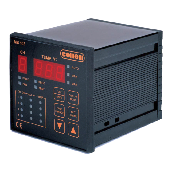
2.2 Hardware characteristics · Container: self-extinguishing ABS Dimensions: box 170 mm x 110 mm x 105 mm (DIN 43700) · Front panel: self-extinguishing Exon Dimensions: 96 mm x 96 mm · Weight: 0.5 kg · Display: Temperature: 3 numbers, each with 7 segments Channel: 7 segments ·... -
Page 8: Rear Panel
2.2.2 Rear panel Auxiliary circuits Probe connection RS-232 port Supply connection Fig. 3 Power supply Terminal number Input Description of operation From 24 to 220V AC to DC universal power supply with +/- 10% variations allowed Earth Must be connected using cable at least 1.5 mm in section From 24 to 220V AC to DC universal power supply with +/- 10% variations allowed Terminal not connected Input for 12V DC power supply... -
Page 9: Main Characteristics
The Temperature Control Unit settings are standard factory values that can be modified as required. The alarm threshold is 140°C with release at 160°C and ventilation excluded. The 19 LEDs on the display allow the MB 103 unit to clearly signal and handle information concerning the temperature situation. 2.5 Temperature display The Temperature Control Unit always switches on in the automatic mode. - Page 10 Profile Setting Active channels Channels with active ventilation CH1, CH2 and CH3 CH 4 CH1, CH2 and CH3 Each channel can be activated as well as the relative ventilation NOTE For profiles 0, 1, 2 and 3, the settings include one single alarm threshold and one single release threshold common to all activated channels.
-
Page 11: S4 Profile
NOTE Confirmation of “nnn” can be displayed at any moment by pressing the key. Use the arrow keys to make changes. Use profile S 4 for maximum freedom when making the settings. PROG Select S 4 and press the key for each confirmation. CHANGE if this option has been selected, programming will follow the Flow-Chart below (consult the previous note when changing and confirming the “n”... -
Page 12: Correct Operation Checks
CAUTION To restore the factory settings, access the programming mode and press key for a few seconds. EXIT CLEAR Do not confirm the last step if you wish to quit the programming mode without saving the changes made to the thresholds. Quitting will occur automatically after about 1 minute. -
Page 13: Installation
L nnn 3. INSTALLATION The MB 103 Temperature Control Unit must be installed inside the switchboard compartment and then fixed in place with the fastening components and screws provided. Connect the power supply (universal power supply 24V – 220V AC/DC or 12V DC). -
Page 14: Operation And Maintenance
Do not install the following components in the same switchboard: high power teleswitches, counters, relays, thyristors and, especially, phase displacement units, motors, etc.). Before applying the MB 103 Temperature Control Unit, wait for the equipment to reach room temperature (at least 1 hour). 5.2 Maintenance Always perform the following inspections on the dehydrator during scheduled maintenance of the transformer: ·... -
Page 15: Fault Monitoring
E-mail: infocomem@it.abb.com 5.4 Movement, transport and storage All MB 103 Temperature Control Units are shipped inside a cardboard box on a pallet to facilitate transport and storage. As soon as the MB 103 Temperature Control Unit is received, the customer must perform the following operations: - examine the outer surface of the packaging to make sure it is intact;... -
Page 16: Software
Create a Log File where all the data can be stored. 6.2 Installation To install the program used by the MB 103 Temperature Control Unit, insert the CD into the PC drive and wait until for the installation procedure autorun. -
Page 17: Use
The installation procedure has now terminated. 6.3 Use Once the program has been installed, click on the start Menu: “Start – Programs – MB 103” to run the software. the following page will appear: The initial window (fig. 9) is divided into 3 parts: 1. -
Page 18: Parameters
6.3.1 Parameters In the Parameters area (fig. 10) you can: Fig. 10 choose which RS 232 to enable: COM1 or COM2; establish the graph sampling time (minimum 2s and maximum 600s); start acquiring data with “Start” or stop data acquisition with “Stop”; display the Log File with the “View”... -
Page 19: Status
For example, Microsoft Excel uses extension “.xls” (fig. 12). Fig. 12 6.3.2 Status Status (fig. 13) allows you to view the settings of the MB 103: Fig. 13 · ON will appear if the temperature detection channel 1) is activated, otherwise OFF will appear. -
Page 20: Temperatures Diagram
The following information appears in the lower part of the Status area (fig. 14): Fig. 14 the active profile; the “Reset Alarm” key: deletes the active alarms if pressed; the “Reset Graph” key: deletes the data shown in the graph (Fig. 15) the visual AutoFan indication: GREEN if on, GREY if off;... - Page 21 Click with the right key of the mouse when on the graph area to display the dialog window and change the parameters ( fig. 16). The main functions are as follows: · Viewing Style: to change the colours of the graph area;...
Need help?
Do you have a question about the MB 103 and is the answer not in the manual?
Questions and answers