Table of Contents
Advertisement
Quick Links
Advertisement
Table of Contents

Subscribe to Our Youtube Channel
Summary of Contents for Dasan V8102
- Page 1 V8102 GPON OLT system User Manual...
- Page 2 UMN:CLI User Manual V8102 ※ Copyright 2017 ⓒ DASAN Network Solutions, Inc. Issued by Technical Documentation Team Korea Technical modifications possible. Technical specifications and features are binding only insofar as they are specifically and expressly agreed upon in a written contract.
- Page 3 UMN:CLI User Manual V8102 Summary of Changes Changes for : Issue 06 Chapter/Section Reason for Update Command in ‘Creating System Account’ section added. 4.1.3.4 Command in ‘Rebooting IUs’ section added. 5.2.3 Command in ‘Displaying Interface’ section added. 5.4.5 ‘Tunneling’ section added.
- Page 4 UMN:CLI User Manual V8102 Commands in ‘Clearing MLD Entry’ section modified. 11.1.3 ‘MLD Proxy’ section added. 11.1.7 ‘MLD-Proxy IF Flap Discredit’ section added. 11.1.7.4 Commands in ‘Displaying MLD Information’ section added. 11.1.8 ‘Explicit Host Tracking’ section added. 11.2.3.5 Commands in ‘Multicast Router Port Configuration’ section add- 11.2.3.6...
- Page 5 UMN:CLI User Manual V8102 ‘Route Server Client’ section added. 12.1.17.33 ‘Sending Community Attirbutes’ section added. 12.1.17.34 ‘Neighbor Shutdown´ section added. 12.1.17.35 ‘Strict Capability Match’ section added. 12.1.17.37 ‘Connection Timer Configuration’ section added. 12.1.17.38 ‘Transparent AS Configuration’ section added. 12.1.17.39 ‘Transparent Nexthoop Configuration’ section added.
- Page 6 UMN:CLI User Manual V8102 Command in ‘Displaying IP Address Assignment’ section added. 5.6.5 Command in ‘Configure External Alarm LEDs’ section added. Command in ‘Transmit Rate’ section modified. 5.10.3 Commands in ‘System Memory’ section added. 6.1.6.5 ‘EQM Debugging’ Section added. 6.1.12 Command in ‘CPU Packet Limit’...
- Page 7 UMN:CLI User Manual V8102 Commands in ‘IGMP Static Join’ section added. 10.1.2.1 Command in ‘MRIB Debug’ added. 10.3.1.10 Command in ‘PIM Mode’ added. 10.3.2.1 Command in ‘Displaying PIM-SM Information’ added. 10.3.3.7 ‘Displaying IP Multicast Interface’ Section added. 10.4 Command in ‘MLD Debug’ section added.
- Page 8 UMN:CLI User Manual V8102 Chapter/Section Reason for Update ‘quote COMMAND’ command added. 3.1.2 Privileged EXEC Enable Mode ‘show cli history list' command added. 3.2.2 Calling Command History ‘user rename NAME_FROM NAME_TO' 4.1.3.4 Creating System Account command added 4.1.9 Telnet Access Telnet access related CLI added.
- Page 9 UMN:CLI User Manual V8102 ‘syslog index snmp' command added. 7.4.3 Syslog index 7.4.7 Displaying Syslog Message Received syslog message related CLI updat- 7.4.8 Uploading Syslog File Uploading syslog files using FTP/TTP related CLI added. 7.7.2.2 Creating MEP Assigning the configured MEP related CLI added.
- Page 10 UMN:CLI User Manual V8102 9.7.1.3 DHCPv6 unique identifier DUID related CLI added. (DUID) ‘vip-access' CLI updated. 9.9.2.2 Access to Associated IP Ad- dress 9.9.3.3 VRRP Debug RRP debugging related CLI added. 9.11.4 Invalid Traffic Guard Invalid Traffic Guard function description add- 9.15...
- Page 11 UMN:CLI User Manual V8102 ‘bgp aggregate-nexthop-check' command 12.1.1.8 BGP Aggregation added. 12.1.1.9 BGP Path Selection RFC1771 configuration related CLI added. 12.1.3 BGP Autonomous System CLI to change the default display and regular Number Formatting expression match format of BGP added.
- Page 12 UMN:CLI User Manual V8102 as Cisco date related CLI added. 12.4.17.1 Displaying RIP Protocol Displaying RIP information related CLI added. Information ‘cisco-metric-behavior ' command added. 12.4.16 RIP Routing Metric Update as Cisco 12.5 Routing Information Protocol Routing Information Protocol Next Generation Next Generation (RIPng) Chapter added.
- Page 13 UMN:CLI User Manual V8102 Issue History Issue Date of Issue SW Release Version for Update Number 10/2015 Initial release 10/2015 Software Release NOS1.02 02/2016 Software Release NOS1.02 05/2016 Software Release NOS1.04 07/2017 Software Release NOS2.01 #0042 08/2017 Software Release NOS2.01 #0042...
-
Page 14: Table Of Contents
UMN:CLI User Manual V8102 Contents 1 Introduction ..................41 Audience ..................... 41 Document Structure................41 Document Convention ................. 42 Document Notation ................42 Virus Protection ................... 43 Declaration of CE Conformity .............. 43 GPL/LGPL Warranty and Liability Exclusion ........43 2 System Overview ................ - Page 15 UMN:CLI User Manual V8102 4.1.3.3 Login Password Recovery Process ..............66 4.1.3.4 Creating System Account ................67 4.1.3.5 Login Banner ....................68 4.1.3.6 Setting Auto Log-out Time ................69 4.1.3.7 Security Level ....................69 4.1.3.8 Limiting Number of Users ................73 4.1.3.9...
- Page 16 UMN:CLI User Manual V8102 5.5.3 Tunnel Address Configuration ..............94 5.5.4 Tunnel Encapsulation Mode ............... 95 Assigning IP Address ................96 5.6.1 Enabling MGMT/VLAN Interface ..............96 5.6.2 Assigning IP Address to Network Interface ..........96 5.6.3 Assigning IPv6 Address ................98 5.6.3.1...
- Page 17 UMN:CLI User Manual V8102 6.1.7 MAC Learning Mode ................. 125 6.1.8 The Utilization and Aging-time of L3 Table ..........126 6.1.9 SD Card ....................126 6.1.10 Power Alarm Configuration ............... 126 6.1.11 Enabling FTP/TFTP Connection ............... 126 6.1.12 EQM Debugging ..................127 System Management .................
- Page 18 UMN:CLI User Manual V8102 7.1.11.4 Generic Alarm Severity ................153 7.1.11.5 ERP Domain Alarm Severity ................ 155 7.1.11.6 ADVA Alarm Severity ................... 155 7.1.11.7 STP Guard Alarm Severity ................156 7.1.11.8 Displaying SNMP Alarm ................157 7.1.12 Displaying SNMP Configuration ............... 157 7.1.13 Disabling SNMP ..................
- Page 19 UMN:CLI User Manual V8102 7.4.8 Uploading Syslog File ................178 7.4.9 Displaying Syslog Configuration ............... 178 Operation, Administration and Maintenance (OAM) ......179 EFM OAM ..................180 7.6.1 Enabling EFM OAM .................. 180 7.6.2 OAM Link Monitoring ................181 7.6.3 EFM OAM Mode ..................
- Page 20 UMN:CLI User Manual V8102 7.7.20.7 Trust Member Port Count ................217 7.7.20.8 Hold Off Time ....................218 7.7.20.9 Wait-to-Restore Time ................... 218 7.7.20.10 Displaying Uplink Redundancy Configuration ..........219 NetBIOS Filtering ................220 Martian Filtering ................221 7.10 Outband Management Port Security ..........221 7.11 Port Mirroring ..................
- Page 21 UMN:CLI User Manual V8102 7.18.10.1 IPv6 Access List ZeBos for ICMP ..............258 7.18.10.2 IPv6 Access List ZeBos for TCP ..............259 7.18.10.3 Access List ZeBos for UDP ................261 7.19 sFlow Monitoring................263 7.19.1 sFlow Setting..................... 263 7.19.1.1 sFlow Function Setup ................... 263 7.19.1.2 sFlow Agent Setting ..................
- Page 22 UMN:CLI User Manual V8102 8.3.5 RADIUS Server ..................293 8.3.5.1 RADIUS Server for System Authentication ..........293 8.3.5.2 RADIUS Server Priority................293 8.3.5.3 Timeout of Authentication Request .............. 293 8.3.5.4 Frequency of Retransmit................293 8.3.6 TACACS+ Server ..................294 8.3.6.1 TACACS+ Server for System Authentication ..........
- Page 23 UMN:CLI User Manual V8102 9.1.2 Protocol-based VLAN ................312 9.1.3 Reserved VLAN ..................312 9.1.4 VLAN Description ..................313 9.1.5 QinQ VLAN Mapping ................314 9.1.5.1 TPID Configuration ..................315 9.1.5.2 One-to-One VLAN Mapping between S-VID and C-VID ......315 9.1.5.3...
- Page 24 UMN:CLI User Manual V8102 9.3.6 Admin Rule ....................348 9.3.6.1 Creating Admin Flow for packet classification ..........349 9.3.6.2 Configuring Admin Flow ................349 9.3.6.3 Applying and modifying Admin Flow ............351 9.3.6.4 Class Creation ..................... 352 9.3.7 Admin Rule Action ..................352 9.3.7.1...
- Page 25 UMN:CLI User Manual V8102 9.4.8.4 Port Priority ....................385 9.4.8.5 Displaying Configuration ................385 9.4.9 Root Guard....................386 9.4.10 Restarting Protocol Migration ..............387 9.4.11 Loop Back Detection ................. 387 9.4.12 BPDU Configuration .................. 388 9.4.12.1 Hello Time ....................389 9.4.12.2 Forward Delay Time ..................
- Page 26 UMN:CLI User Manual V8102 9.6.5.3 Deleting DHCP Option Format ..............411 9.6.5.4 Displaying DHCP option ................411 9.6.6 DHCP Option 82 ..................411 9.6.6.1 Enabling DHCP Option 82 ................412 9.6.6.2 Option 82 Sub-Option .................. 413 9.6.6.3 Option 82 Reforwarding Policy ..............414 9.6.6.4...
- Page 27 UMN:CLI User Manual V8102 9.7.2.4 DHCP Lease Limit ..................439 9.7.2.6 DHCP Snooping Option ................440 9.7.2.7 Displaying DHCPv6 Snooping Configuration ..........441 9.7.3 DHCPv6 Relay Agent ................442 9.7.3.1 DHCPv6 Relay Agent Destination ..............442 9.7.4 DHCPv6 Option ..................442 9.7.4.1...
- Page 28 UMN:CLI User Manual V8102 9.14 Jumbo Frame Capacity ..............468 9.15 Configuring PPPoE Tag Option Format ..........469 9.15.1 PPPoE Vendor Tag Option ............... 469 9.15.1.1 Entering PPPoE Vendor Tag Option Mode ..........469 9.15.1.2 Configuring PPPoE Vendor Tag Option Format ........... 469 9.15.1.3 Deleting PPPoE Vendor Tag Option Format ..........
- Page 29 UMN:CLI User Manual V8102 10.2.3.7 Multicast Router Port Configuration ............. 497 10.2.3.8 TCN Multicast Flooding ................499 10.2.4 IGMPv3 Snooping ..................502 10.2.5 Displaying IGMP Snooping Information ............ 503 Multicast VLAN Registration (MVR) ..............504 10.2.5.1 Enabling MVR ....................504 10.2.5.2 MVR Group ....................
- Page 30 UMN:CLI User Manual V8102 10.3.3.2 Bootstrap Router ..................533 10.3.3.3 Source Registration ..................534 10.3.3.4 SPT Switchover ................... 536 10.3.3.5 Cisco’s Router Interoperability ..............536 10.3.3.6 Debugging PIM-SM ..................538 10.3.3.7 Displaying PIM-SM Information ..............539 10.3.4 Source Specific Multicast (SSM) .............. 539 10.3.4.1 PIM-SSM .....................
- Page 31 UMN:CLI User Manual V8102 11.3 IPv6 Multicast Routing ............... 566 11.3.1 Multicast Routing ..................566 11.3.1.1 Enabling Multicast Routing ................566 11.3.1.2 ECMP Load Splitting ..................566 11.3.1.3 MRIB Entry Limit ..................567 11.3.1.4 Creating Multicast Static Route ..............568 11.3.1.5 Displaying MRIB Entry .................
- Page 32 UMN:CLI User Manual V8102 12.1.1 Basic Configuration .................. 596 12.1.1.1 Configuration Type of BGP ................596 12.1.1.2 Enabling BGP Routing ................. 597 12.1.1.3 Router ID ..................... 597 12.1.1.4 Enabling ASN Capabilities ................598 12.1.1.5 Registering BGP Neighbor ................598 12.1.1.7 Maximum Path ..................... 599 12.1.1.8 BGP Aggregation ..................
- Page 33 UMN:CLI User Manual V8102 12.1.17.16 Graceful Restart ..................624 12.1.17.17 ORF Prefix-list Configuration ..............624 12.1.17.18 Route Reflesh Configuration..............625 12.1.17.19 Collide-established Configuration ............625 12.1.17.20 Connection Retry Time Configuration ............626 12.1.17.21 Neighbor Description ................626 12.1.17.22 Infinite Holdtime Disallowance ..............626 12.1.17.23...
- Page 34 UMN:CLI User Manual V8102 12.2.4.7 OSPF Maximum Transmission Unit (MTU) ..........655 12.2.4.8 OSPF Priority ....................656 12.2.4.9 OSPF Network Type ..................656 12.2.4.10 Disabling OSPF Packet Processing ............. 657 12.2.5 Non-Broadcast Network ................657 12.2.6 OSPF Area ....................658 12.2.6.1 Area Authentication ..................
- Page 35 UMN:CLI User Manual V8102 12.3.14 OSPFv3 Distance..................697 12.3.15 OSPFv3 Monitoring and Management ............. 697 12.3.15.1 Displaying OSPFv3 Information ..............697 12.3.15.2 Logging Neighbor Changes................699 12.3.15.3 Limiting Number of Database ............... 699 12.3.15.4 Displaying Debugging Information ............... 700 12.4 Routing Information Protocol (RIP) ............ 701 12.4.1 Enabling RIP .....................
- Page 36 UMN:CLI User Manual V8102 12.5.16 Monitoring and Managing RIPng ............. 721 12.5.16.1 Displaying RIPng Protocol Information ............722 12.5.16.2 Displaying Debugging Information ............... 722 12.6 Route Map for IP Routing Protocol ............ 724 12.7 Virtual Routing and Forwarding (VRF) ..........728 12.7.1 Configuring VRF Routing Table ...............
- Page 37 UMN:CLI User Manual V8102 13.10.4 Displaying PM Profile Information ............. 880 13.10.5 Displaying ONU Traffic Statistics .............. 880 13.10.6 Sample Configuration ................881 13.11 Multicast Profile ................. 882 13.11.1 Creating Multicast Profile ................882 13.11.2 IGMP Configurations ................. 883 13.11.3 Saving Multicast Profile ................884 13.11.4 Applying Multicast Profile ................
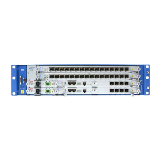
- Page 38 UMN:CLI User Manual V8102 Illustrations Fig. 2.1 Front View of the V8102 ................45 Fig. 5.1 Slot Assignment of V8102 ................86 Fig. 5.2 Structure of IPv6 Header ................98 Fig. 6.1 Ping Test for Network Status ............... 130 Fig. 6.2 IP Source Routing ..................
- Page 39 The V8102 with IGMP Snooping ..............475 Fig. 10.2 The V8102 with PIM-SM ................476 Fig. 10.3 The V8102 with IGMP Snooping and PIM-SM ..........476 Fig. 10.4 IGMP Snooping .................... 489 Fig. 10.5 Multicast Equal Cost Multipath (ECMP) ............518 Fig.
- Page 40 UMN:CLI User Manual V8102 Tables Tab. 1.1 Overview of Chapters ..................41 Tab. 1.2 Command Notation of Guide Book..............42 Tab. 3.1 Main Command of Privileged EXEC View Mode .......... 50 Tab. 3.2 Main Command of Privileged EXEC Enable Mode ........50 Tab.
-
Page 41: Introduction
V8102 1 Introduction Audience This manual is intended for V8102 multi-platform PON OLT system operators and maintenance personnel for providers of Gigabit passive optical network (GPON) and Ethernet services. This manual assumes that you are familiar with the following: •... -
Page 42: Document Convention
UMN:CLI User Manual V8102 Document Convention This guide uses the following conventions to convey instructions and information. Information This information symbol provides useful information when using commands to configure and means reader take note. Notes contain helpful suggestions or references. -
Page 43: Virus Protection
GPL/LGPL Warranty and Liability Exclusion The Dasan product, V8102, contains both proprietary software and “Open Source Soft- ware”. The Open Source Software is licensed to you at no charge under the GNU Gen- eral Public License (GPL) and the GNU Lesser General Public License (LGPL). - Page 44 Open Source Software contained in this product, please consult the GPL and LGPL. You have no warranty claims against Dasan when a defect in the product is or could have been caused by changes made by you in any part of the software or its configuration. In addition, you have no warranty claims against Dasan when the Open Source Software in- fringes the intellectual property rights of a third party.
-
Page 45: System Overview
32-Port GPON interfaces per chassis. You can insert or pull out the plug-in units to/from the chassis in easy and safe way. The V8102 provides 7 slots for the plug-in units. Each type of interface unit contains dif- ferent number of ports. The two slots are reserved for the SFU cards for manage- ment/switching. -
Page 46: System Features
Network operator can use MIB also to monitor and manage the V8102. IP Routing The V8102 is Layer 3 switch, which has routing table and IP address as router. Therefore, it supports static routing, RIPv1/v2, OSPFv2 and BGPv4 for unicast routing. - Page 47 V8102 Spanning Tree Protocol (STP) To prevent loop and preserve backup route in Layer 2 network, the V8102 supports Spanning Tree Protocol (STP) defined in IEEE 802.1D. Between STP enabled switches, a root bridge is automatically selected and the network remains in tree topology. However, the recovery time in STP is very slow (about 30 seconds), Rapid Spanning Tree Protocol (RSTP) is also provided.
- Page 48 Outband Management Interface The V8102 can connect to equipments at remote place by assigning IP address to MGMT interface. Since MGMT interface is operated regardless of status of service port, it is still possible to configure and manage equipment at remote place even though problem such as link disconnection is occurred.
-
Page 49: Command Line Interface (Cli)
V8102 connects inband to the cascading switch, and then from the cascading switch to the management network through the outband interface. The V8102 also provides the RS232 console interface to simply access the system with a provided RJ45-to-DB9 cable. -
Page 50: Privileged Exec View Mode
UMN:CLI User Manual V8102 3.1.1 Privileged EXEC View Mode When you log in to the switch, the CLI will start with Privileged EXEC View mode which is a read-only mode. In this mode, you can see a system configuration and information with several commands. -
Page 51: Global Configuration Mode
UMN:CLI User Manual V8102 3.1.3 Global Configuration Mode In Global Configuration mode, you can configure general functions of the system. You can also open another configuration mode from this mode. To open Global Configuration mode, enter the configure terminal command, and then the system prompt will be changed from SWITCH# to SWITCH(config)#. -
Page 52: Interface Configuration Mode
The Ethernet Interface mode contains commands for configuring the 1GE or 10GE inter- face. You can open this Interface Configuration mode when at least one SFU_10GE4 module is installed in the V8102 chassis. To open Ethernet Interface Configuration mode, enter the interface gigabitether- net/tengigabitethernet command, then the system prompt will be changed from SWITCH(config)# to SWITCH(config-if[GE])# or SWITCH(config-if[XE])#. -
Page 53: Gpon Interface Mode
You can configure the system to be accessed remotely by Telnet. Firstly, you have to in- stall the SFU module in the central slot of the chassis. The V8102 has a management port (MGMT) and console port on the front panel of SFU module. -
Page 54: Channel Group Mode
DHCP Pool Configuration Mode In DHCP Pool Configuration mode, you can configure general functions of DHCP per each DHCP pool. The V8102 supports multiple DHCP environments with this pool-based DHCP configuration. To open DHCP Pool Configuration mode, enter the ip dhcp pool command, then the sys- tem prompt will be changed from SWITCH(config)# to SWITCH(config-dhcp[POOL])#. -
Page 55: Dhcp Option Configuration Mode
UMN:CLI User Manual V8102 To open DHCP Pool Configuration mode, use the service dhcp command in the Global Configuration mode first! Tab. 3.4 shows main commands of DHCP Pool Configuration mode. Command Description default-router Configures the default gateway of the pool. -
Page 56: Rule Configuration Mode
Main Command of Rule Configuration Mode 3.1.9 RMON Configuration Mode In RMON Configuration mode, you can configure RMON alarm, RMON event and RMON history. The V8102 provides three different configuration modes to configure each type of RMON. Command Mode Description rmon-alarm <1-65535>... -
Page 57: Router Configuration Mode
Router Configuration Mode In Router Configuration mode, you can configure IP routing protocols and VRRP. The V8102 provides three IP routing protocols such as RIP v2, BGPv4 and OSPFv2. To open Rule Configuration mode, enter the router command, then the system prompt will be changed from SWITCH(config)# to SWITCH(config-router)#. -
Page 58: Gpon Configuration Mode
UMN:CLI User Manual V8102 <0-65535> Tab. 3.10 shows main commands of Route-map Configuration mode. Command Description match Classifies routing information to permit or deny. Configures routing information options. Tab. 3.10 Main Command of Route-map Configuration Mode 3.1.12 GPON Configuration Mode There are two GPON Configuration mode;... -
Page 59: Useful Tips
To list available commands, input question mark <?> in the current mode. When you input the question mark <?>, you can see available commands used in this mode and variables following after the commands. The following is the available commands on Privileged EXEC Enable mode of the V8102. SWITCH# ? Exec commands:... - Page 60 Press the <ENTER> key to skip to the next list. In case that the V8102 installed command shell, you can find out commands starting with a specific alphabet. Input the first letter and question mark without space. The following is an example of finding out the commands starting “s”...
-
Page 61: Calling Command History
UMN:CLI User Manual V8102 The V8102 also provides the simple instruction of calling the help string with the help command. You can see the instruction using the command regardless of the configuration mode. To display the instruction of calling the help string for using CLI, use the following com- mand. - Page 62 UMN:CLI User Manual V8102 To save the command history in non-volatile memory, use the following command. Command Mode Description Saves a command history. history non-volatile [<10-2000>] 10-2000: history recording max. count (default:2000) Global history non-volatile sdcard {cli | Enables the system to store CLI/SNMP log history in a snmp} local SD card.
-
Page 63: Using Abbreviation
UMN:CLI User Manual V8102 [default] Global command-history-log disable Disables the command history logging. [default] To display the configured status of command history logging, use the following command. Command Mode Description show command-history-log Enable Shows the command history logging status. status Global 3.2.3... -
Page 64: System Basic Configuration And Operation
4 System Basic Configuration and Operation Basic Configuration After installing the system, the V8102 is supposed to examine that each port is correctly connected to network and management PC. You can connect to the system to configure and manage the V8102. This section provides instructions how to change password for system connection and how to connect to the system through telnet. -
Page 65: Configuring System Login Information
UMN:CLI User Manual V8102 4.1.3 Configuring System Login Information 4.1.3.1 Password for Privileged EXEC Enable Mode You can configure a password to enhance the security for Privileged EXEC Enable mode. To configure a password for Privileged EXEC Enable mode, use the following command. -
Page 66: Changing Login Password
Login Password Recovery Process To recovery login password to default, perform the following step-by-step instruction: Step 1 After the V8102 is manually restarted, the booting messages are shown up. Keep on “[Loading OS1 image ...]” pressing [Space Bar] key right after is shown up on the screen. -
Page 67: Creating System Account
4.1.3.4 Creating System Account For the V8102, the administrator can create a system account. In addition, it is possible to set the security level from 0 to 15 to enhance the system security. To create a system account, use the following command. -
Page 68: Login Banner
UMN:CLI User Manual V8102 The account of level 0 to level 14 without any configuring authority only can use exit and help in Privileged EXEC View mode and cannot access to Privileged EXEC Enable mode. The account with the highest level 15 has a read-write authority. -
Page 69: Setting Auto Log-Out Time
4.1.3.7 Security Level For the V8102, it is possible to configure the security level from 0 to 15 for a system ac- count. The level 15, as the highest level, has a read-write authority. The administrator can configure from level 0 to level 14. The administrator decides which level user uses which commands in which level. - Page 70 UMN:CLI User Manual V8102 privilege interface level <0-15> {COMMAND | Uses the specific command of Interface all} Configuration mode in the level. Uses the specific command of VRRP Con- privilege vrrp level <0-15> {COMMAND | all} figuration mode in the level.
- Page 71 UMN:CLI User Manual V8102 The commands that are used in low level can be also used in the higher level. For exam- ple, the command in level 0 can be used in from level 0 to level 14. The commands should be input same as the displayed commands by show list. There- fore, it is not possible to input the commands in the bracket separately.
- Page 72 UMN:CLI User Manual V8102 no privilege ospf level <0-15> {COMMAND | all} no privilege rmon-alarm level <0-15> {COMMAND | all} no privilege rmon-event level <0-15> {COMMAND | all} no privilege rmon-history level <0-15> {COMMAND | all} no privilege dhcp-pool level <0-15> {COMMAND | all} no privilege dhcp-pool-class level <0-15>...
-
Page 73: Limiting Number Of Users
4.1.3.8 Limiting Number of Users For the V8102, you can limit the number of users accessing the switch through telnet. In case of using the system authentication with RADIUS or TACACS+, a configured number includes the number of users accessing the switch via the authentication server. To set the number of users accessing the switch, use the following command. -
Page 74: System Rebooting
If you reboot the system without saving new configuration, new configuration will be de- leted. So, you have to save the configuration before rebooting. Not to make that mistake, the V8102 is supported to print the following message to ask if user really wants to reboot and save configuration. -
Page 75: Configuring Host Name And Time
Shows system time and date. Global The V8102 can be configured to observe the daylight saving time in specified area. It means that whenever the system time is updated using a time server located in a differ- ent time area, it will be automatically corrected with the local daylight saving time offset. -
Page 76: Time Zone
4.1.5.3 Time Zone The V8102 provides three kinds of time zone, GMT, UCT and UTC. The time zone of the switch is predefined as GMT (Greenwich Mean Time). You can also set the time zone where the network element belongs. -
Page 77: Network Time Protocol (Ntp)
UMN:CLI User Manual V8102 The following table shows the world time zone. Time Zone Country/City Time Zone Country/City GMT-12 International Date Line West GMT+12 Wellington, Fiji GMT-11 Midway Island, Samoa, Pago Pago GMT+11 Magadan, New Caledonia GMT-10 Hawaii, Honolulu GMT+10... -
Page 78: Simple Network Time Protocol (Sntp)
UMN:CLI User Manual V8102 To display a configured NTP, use the following command. Command Mode Description Enable show ntp Shows a configured NTP function. Global To synchronize the system clock, the system periodically sends the NTP message to the NTP server. You can configure the system to bind the IP address to the message which allows the NTP server to recognize your system. -
Page 79: Dns Server
UMN:CLI User Manual V8102 no sntp SERVER1 [SERVER2] Deletes a specified SNTP server. [SERVER3] no sntp Disables SNTP function. You can configure up to 3 servers so that you use second and third servers as backup use in case the first server is down. -
Page 80: Ftp Server
If the FTP server is disabled, the system software upgrade cannot be done via FTP serv- 4.1.8 Auto Log-out For security reasons of the V8102, if no command is entered within the configured inactiv- ity time, the user is automatically logged out of the system. Administrator can configure the inactive session timeout. -
Page 81: Telnet Access
UMN:CLI User Manual V8102 4.1.9 Telnet Access To activate/deactivate the connection to a remote host via telnet, use the following com- mand. Command Mode Description service telnet Activates the telnet service. Global no service telnet Deactivates the telnet service. Shows the status of network connection services... -
Page 82: System Configuration Management
UMN:CLI User Manual V8102 SWITCH# where admin at ttys0 from console for 4 days 22 hours 15 minutes 34.88 seconds admin at ttyp1 from 147.54.140.133:49538 for 6 minutes 44.12 seconds SWITCH# System Configuration Management 4.2.1 Displaying System Configuration To display the current running configuration of the system, use the following command. -
Page 83: Writing System Configuration
4.2.4 Auto-Saving The V8102 supports the auto-saving feature, allowing the system to save the system con- figuration automatically. This feature prevents the loss of unsaved system configuration by unexpected system failure. To allow the system to save the system configuration au- tomatically, use the following command. -
Page 84: Restoring Default Configuration
UMN:CLI User Manual V8102 To back up a system configuration file using FTP or TFTP, use the following command. Command Mode Description copy {ftp | tftp} config upload {FILE- Uploads a file to FTP or TFTP server with the NAME | startup-config} name configured by user. -
Page 85: Core Dump File
The V8102 can be configured to generate core dumps and save them in ramdisk for useful debugging aids in several situations such as access- es to non-existent memory, segmentation errors. -
Page 86: Equipment/Interface Management
The V8102 has the reserved 2 slots for SIUs. IUs Management In V8102 shelf, there are 2 slots for SIUs. By default, all of IU slots are in admin ‘locked’ state that IUs are unable to operate normally even though they are properly inserted into the shelf with power-up. -
Page 87: Ius Replacement
UMN:CLI User Manual V8102 ly operated. Step 1 Configure a slot for the specified IU type, use the following command. Command Mode Description Specifies an IU type in a slot. slot planning iu SLOT_NUMBER {siu-gpon16 | Global SLOT_NUMBER : the slot number of IU sfu-10ge4} (e.g. -
Page 88: Rebooting Ius
UMN:CLI User Manual V8102 Step 3 Register new IU in the slot. Command Mode Description slot planning iu SLOT_NUMBER {siu-gpon16 | Global Specifies an IU type in a slot. sfu-10ge4} Step 4 Replace the old IU with the new IU. Insert new IU into the intended slot. - Page 89 UMN:CLI User Manual V8102 {SLOT_NUMBER | all} show slot {SLOT_NUMBER | all} show slot status {SLOT_NUMBER | all} show slot system all show slot system {SLOT_NUMBER | all} show slot system sfu [mate]...
-
Page 90: Interface Basic
V8102. 5.3.1 IU Interface Port Numbering Scheme The V8102 provides 2 service slots for GPON interface unit (SIU_GPON16). Each type of interface unit contains 16 ports, which means the V8102 provides maximum 32 physical ports. When specifying the port number for the OLT ID for SIU_GPON16 in the CLI, you can simply put the number in the form of SLOT/PORT such as 1/1, 1/2, 1/3, …, 2/16. -
Page 91: Enabling An Interface
UMN:CLI User Manual V8102 Command Mode Description interface {gigabitethernet Opens Ethernet/GPON Interface Configuration mode to tengigabitethernet gpon configure a specified interface. IFPORT IFPORT: SLOT/PORT interface channelgroup GROUP- Opens Channel Group Interface Configuration mode. Global Interface Opens Ethernet/GPON Interface Configuration mode to... -
Page 92: Interface Traffic Statistics
UMN:CLI User Manual V8102 5.4.4 Interface Traffic Statistics 5.4.4.1 Packet Statistics To display the traffic statistics of an Ethernet port, use the following command. Command Mode Description show interface statistics {avg | Shows the traffic statistics of the average packet for a interface | rmon | 5min} all specified Ethernet port. -
Page 93: Interface Identifier
UMN:CLI User Manual V8102 Command Mode Description show interface-status [{gigabitethernet tengigabitethernet | gpon | channelgroup} Shows a current port status, enter a port IFPORTS] number. show interface status [{gigabitethernet | PORTS: port number (1/1, 1/2, 2/1, …) Enable tengigabitethernet | gpon | channelgroup}... -
Page 94: Tunneling
UMN:CLI User Manual V8102 Tunneling This chapter contains commands for IP tunneling. 5.5.1 Opening Tunnel Interface Mode You can create a tunnel interface and then configure the logical interface for your IP tun- nel. To open Interface tunnel mode, enter the interface tunnel command, then the system prompt will be changed from SWITCH(config)# to SWITCH(config-if[tunnel#])#. -
Page 95: Tunnel Encapsulation Mode
UMN:CLI User Manual V8102 5.5.4 Tunnel Encapsulation Mode tunnel mode command specifies a tunnel encapsulation mode for either GRE and IPIP mode The GRE tunnel mode is used for IPv6-to-IPv6 tunneling. To configure an IPv6 tunnel mode, use the following command. -
Page 96: Assigning Ip Address
The Layer 2 switches do not need IP addresses to transmit packets. However, if you want to access to the V8102 from a remote place with TCP/IP through SNMP or telnet, it requires an IP address. - Page 97 UMN:CLI User Manual V8102 ip address A.B.C.D/M primary [MGMT/VLAN/LO] Assigns a primary IP address to an interface. ip address A.B.C.D/M secondary Assigns a secondary IP address to an interface. ip address dhcp Assigns an IP address from a DHCP server.
-
Page 98: Assigning Ipv6 Address
UMN:CLI User Manual V8102 5.6.3 Assigning IPv6 Address IPv6 is designed as an evolutionary step from IPv4. IPv6 runs well on high performance networks like Gigabit Ethernet, ATM, and others, as well as low bandwidth networks. The main changes from IPv4 to IPv6 are summarized as follows: •... -
Page 99: Tab. 5.3 Overview Of Ipv6 Header Fields
UMN:CLI User Manual V8102 Tab.4.1 provides an overview of the IPv6 header fields. Field Description Version Version of the protocol (4 Bits) This field replaces the Type of Service field in IPv4. This field is used by sending Priority nodes and forwarding routers to identify and distinguish between different classes or priorities of IPv6 packets. -
Page 100: Assigning Ipv6 Address To Network Interface
UMN:CLI User Manual V8102 IPv6 Address Types IPv6 uses multicast addresses instead of the broadcast address. An IPv6 address can be classified into one of three categories, which Unicast, Multicast and Anycast address. The Anicast address, a new type of address introduced with RFC 1546, is now used with IPv6. -
Page 101: Assigning Link Local Address To Network Interface
UMN:CLI User Manual V8102 The IPv6 address is automatically learned and based upon the received Router Adver- tisement from its upstream service provider router. To enable/disable automatic configuration of IPv6 addresses using stateless auto configu- ration on an interface, use the following command. -
Page 102: Static Route And Default Gateway
UMN:CLI User Manual V8102 To disable an assigned IPv6 link-local address, use the following command. Command Mode Description Interface no ipv6 address link-local Clears a link-local address assigned to an interface. [MGMT/VLAN/ Static Route and Default Gateway 5.6.3.3 The static route is a predefined route to a specific network and/or device such as a host. -
Page 103: Enabling Ipv6 Processing
UMN:CLI User Manual V8102 static] To remove all kernel IPv6 route caches, use the following command. Command Mode Description clear ipv6 route kernel Enable Removes all kernel IPv6 route caches 5.6.3.4 Enabling IPv6 Processing To enable/disable the IPv6 processing on an interface, use the following command. -
Page 104: Displaying Ipv6 Interface
UMN:CLI User Manual V8102 no ipv6 mode Deletes the configured IPv6 interface mode. Displaying IPv6 interface 5.6.3.6 To display an assigned IPv6 address, use the following command. Command Mode Description show ipv6 Interface Shows the IPv6 addresses assigned to an interface. -
Page 105: Static Route And Default Gateway
UMN:CLI User Manual V8102 5.6.4 Static Route and Default Gateway The static route is a predefined route to a specific network and/or device such as a host. Unlike a dynamic routing protocol, static routes are not automatically updated and must be manually reconfigured if the network topology changes. -
Page 106: Displaying Ip Address Assignment
You can configure the system to be accessed remotely by Telnet. Firstly, you have to in- stall the SFU module in the central slot of the chassis. The V8102 has a management port (MGMT) and console port on the front panel of SFU module. - Page 107 5. Save the IP settings so that they will be in effect after the next system reboot by reload command. 6. Once you have completed the proper hardware installation and initial software configuration for the V8102, you can access the system remotely by Telnet. The following is an example of accessing the system remotely. SWITCH login: admin Password: SWITCH>...
-
Page 108: Sfu Redundancy
Switching Fabric Interface Redundancy There are two slots for SFU in the rear of the V8102 base chassis. A redundant SFU could be equipped into either slot. This switch can perform normal switching operation with a single SFU, but also can accommodate dual SFUs to ensure stable operation. -
Page 109: Fault Monitoring Function
5.7.2 Fault Monitoring Function You can also configure the V8102 to monitor the fault of the SFU daemons for automatic SFU switchover for a connection failure. If a certain daemon (eqmd, swchd, nsm, snmpd, ripd, updated, etc.) is terminating ab- normally or no response is received from the daemon, you can define the action. -
Page 110: Data Synchronization Between Sfus
5.7.3 Data Synchronization between SFUs If there are dual SFUs in V8102 chassis, the currently saved configuration data of active SFU can be copied and moved to standby SFU. To synchronize the configuration data be- tween SFUs for redundancy control, use the following command. -
Page 111: Configure External Alarm Leds
In addition, V8102 can monitor the external alarm LEDs on the switch fabric unit (SFU) card using SNMP alarm severity settings or alarm LED level setting. If you set the critical severity of the SNMP alarm, the system will generate trap messages and turn on the CRIT alarm LED when corresponding events occur. - Page 112 UMN:CLI User Manual V8102 To block/unblock the alarm LED configurations according to the level of alarm LEDs, use the following command. Command Mode Description alarm-led block {all | critical | Blocks the alarm LED configuration. major | minor} Global alarm-led unblock {all | critical | Unblocks the alarm LED configuration.
-
Page 113: Iu Firmware Upgrade
UMN:CLI User Manual V8102 IU Firmware Upgrade 5.9.1 Manually Upgrading SFU To upgrade the system software of the switch, use the following command. Command Mode Description Upgrades the system software of the switch via FTP or copy {ftp | tftp} os download Enable TFTP. -
Page 114: Manually Sfu Firmware Uploading
UMN:CLI User Manual V8102 To restart a specific IU in the slot using the following command. Command Mode Description Resets an interface module in the specified slot num- slot restart iu SLOT_NUMBER Global ber. To display the new system software using the following command. -
Page 115: Ethernet Port Configuration
The Ethernet Interface mode contains commands for configuring the 1GE or 10GE inter- face. You can open this Interface Configuration mode when at least one SFU_10GE4 module is installed in the V8102 chassis. To open Ethernet Interface Configuration mode, enter the interface gigabitether- net/tengigabitethernet command, then the system prompt will be changed from SWITCH(config)# to SWITCH(config-if[GE])# or SWITCH(config-if[XE])#. -
Page 116: Transmit Rate
UMN:CLI User Manual V8102 Auto-negotiation operates only on 10/100/1000Base-T interface. You cannot enable this function on 1000Base-X or 10GbE optical interface. 5.10.3 Transmit Rate To set the transmit rate of a 10G Ethernet port, use the following command. Command Mode... -
Page 117: Network Service Port
UMN:CLI User Manual V8102 To configure the interval for link monitoring on the Ethernet port, use the following com- mand. Command Mode Description Specifies the time interval for checking the link of Ethernet interface. link-check-timer <20-1000> 20-1000: interval value (in milliseconds, default:... -
Page 118: Flow Control
UMN:CLI User Manual V8102 To specify MDI mode on an Ethernet port, use the following command. Command Mode Description Specifies MDI mode of port. auto: auto MDI mode Interface mdi {auto | normal | cross} cross: Disable auto-MDI crossover and swap cable... -
Page 119: System Environment
Enable no terminal length Restores a default line displaying. 6.1.2 Fan Operation For the V8102, it is possible to control fan operation. To control fan operation, use the fol- lowing command. Command Mode Description fan operation full Operates the fans at full-speed. -
Page 120: Ftp Bind Address
IP address. However, an interface of the V8102 may have multiple IP addresses. In such a multiple-IP environment, a primary IP address is normally used. You can configure the V8102 to use one of the secondary IP addresses as a source IP of an FTP client. -
Page 121: Sfp Module Operation
UMN:CLI User Manual V8102 Command Mode Description module ddm {enable | disa- Specifies whether to collect DDM information Global ble} all from all SFP modules. module ddm {enable | disa- Interface Specifies whether to collect DDM information ble} [GE/XE/GPON] from SFP modules in the specified interface. -
Page 122: System Threshold
6.1.6 System Threshold You can configure the system with various kinds of the system threshold such as CPU load, traffic, temperature, etc. Using this threshold, the V8102 generates syslog messag- es, sends SNMP traps, or performs a relevant procedure. 6.1.6.1 CPU Load To set the threshold of CPU load, use the following command. -
Page 123: Port Traffic
UMN:CLI User Manual V8102 6.1.6.2 Port Traffic To set the threshold of port traffic, use the following command. Command Mode Description Sets the threshold of port traffic. PORTS: port number (1/1, 1/2, 2/1, …) threshold THRESHOLD {5 | 60 | 600} {rx | tx}... -
Page 124: System Temperature
UMN:CLI User Manual V8102 To display the configured threshold of fan operation, use the following command. Command Mode Description Shows the status and configured threshold of show status fan Enable/Global fan operation. 6.1.6.4 System Temperature To set the threshold of system temperature, use the following command. -
Page 125: System Memory
NUM] 6.1.7 MAC Learning Mode The V8102 supports two methods of MAC learning that are CPU-based learning (CML) and the switching fabric-based learning (SML). You can choose the way how to learn MAC addresses by CLI. The following table shows the functional performance of CML mode and SML mode. -
Page 126: The Utilization And Aging-Time Of L3 Table
UMN:CLI User Manual V8102 6.1.8 The Utilization and Aging-time of L3 Table To display the urtilization of packets in use on L3 interface, host entries, LPM entries and L3 ECMP entries, use the following command. Command Mode Description Enable Shows the usage of L3 interface, host, LPM, ECMP... -
Page 127: Eqm Debugging
UMN:CLI User Manual V8102 service ftp Global Enables/ disables the connection via FTP. no service ftp To enable/disable the connection via TFTP, use the following command. Command Mode Description service tftp Global Enables/ disables the connection via TFTP. no service tftp To display the status of network connection services, use the following command. -
Page 128: System Management
UMN:CLI User Manual V8102 System Management When there is any problem in the system, you must find what the problem is and its solu- tion. Therefore, you should not only be aware of a status of the system but also verify if the system is correctly configured. -
Page 129: Tab. 6.3 Options For Ping For Multiple Ip Addresses
UMN:CLI User Manual V8102 108 bytes from 10.55.193.110: icmp_seq=4 ttl=255 time=1.63 ms 108 bytes from 10.55.193.110: icmp_seq=5 ttl=255 time=0.414 ms --- 10.55.193.110 ping statistics --- 5 packets transmitted, 5 received, 0% packet loss, time 8008ms rtt min/avg/max/mdev = 0.058/0.581/1.632/0.542 ms... -
Page 130: Ip Icmp Source Routing
In Fig. 6.2, if you perform ping test from PC to C, it goes through the route of A→B→C. This is the general case. But, the V8102 can enable to perform ping test from PC as the route of A→E→D→C. -
Page 131: Tracing Packet Route
To perform ping test as the route which the manager designated, use the following steps. Step 1 Enable IP source-routing function from the equipment connected to PC which the PING test is going to be performed. To enable/disable IP source-routing in the V8102, use the following command. Command Mode Description ip icmp source-route Enable IP source-routing function. -
Page 132: Displaying User Connecting To System
UMN:CLI User Manual V8102 The followings are the configurable options to trace the routes. Items Description Protocol [ip] Supports ping test. Default is IP. Sends ICMP echo message by inputting IP address or host name of Target IP address destination in order to check network status with relative. -
Page 133: Mac Table
Command Mode Description Enable show system Shows the system information. Global The following is an example of displaying the system information of the V8102. SWITCH(config)# show system SysInfo(System Information) Model Name : V8102_SFU Main Memory Size : 2048 MB Flash Memory Size... -
Page 134: System Memory Information
UMN:CLI User Manual V8102 SWITCH(config)# 6.2.8 System Memory Information To display a system memory status, use the following command. Command Mode Description show memory [all] Shows system memory information. show memory {bgp | dhcp | eqm Enable | free | gpon | hwmon | imi | ipv6... -
Page 135: Slowpath Filtering
User Manual V8102 The V8102 provides CPU storm control feature for mass ARP, DHCP, and IGMP packet. Generally, wrong network configuration, hardware malfunction, virus and so on cause these kinds of mass packets. The packet storm occupies most of the bandwidth of the network, and that causes the network very unstable. - Page 136 UMN:CLI User Manual V8102 To configure one or more packet filter match pattern(s), use the following command. Command Mode Description match vid <1-4094> [tag-position Classifies a VLAN ID. <1-8>] VLAN: VLAN ID Classifies a queue of CPU RX/TX packets. match cos <0-7>...
- Page 137 UMN:CLI User Manual V8102 Command Mode Description no match protocol { icmp | igmp} no match protocol { tcp | udp} [{srcport PORT | dstport PORT}] To specify the action policy of slowpath packet filter for the packets matching the config- ured match patterns, use the following command.
-
Page 138: Cpu Statistics
UMN:CLI User Manual V8102 apply Saves and applies the configured slowpath packet filter To display the configured slowpath packet filter, use the following command. Command Mode Description show slowpath-filter [NAME] Shows the configured slowpath packet filter. Enable Global show running-config slowpath-... -
Page 139: Running Process
User Manual V8102 The V8102 can be configured to generate a syslog message when the number of the packets handled by CPU exceeds a specified value. This function allows system adminis- trators to monitor the switch and network status more effectively. To configure the switch to generate a syslog message according to the number of the packets handled by CPU, use the following command. -
Page 140: Displaying System Software
6.2.13 Default OS The V8102 supports the dual OS feature. You can verify the running OS in the flash memory with the show flash command. When two system Oss are installed, you can set one of those as the default OS. -
Page 141: Switch Status
UMN:CLI User Manual V8102 Sets the default OS of the system. default-os {os1 | os2} Enable (default: os1) 6.2.14 Switch Status To display the temperature of switch, power status, and fan status, use the following command. Command Mode Description show status fan Shows the fan status of the switch. -
Page 142: Tech Support Information
To reduce the effort to acquire the detail informtation of the system for a technical suppport, the V8102 provides the function that generates all the system information reflecting the current state. Using this function, you can verify all the details on a console screen or even in the remote place via FTP/TFTP. -
Page 143: Network Service Module (Nsm) Informtaion
UMN:CLI User Manual V8102 6.2.18 Network Service Module (NSM) Informtaion To display the information of the NSM Client, use the following command. Command Mode Description Enable show nsm client Shows the information of the NSM client. Global 6.2.19 Network Service Module (NSM) Daemon Debugging To enable NSM daemon debugging, use the following command. -
Page 144: Protocol Statistics Information
UMN:CLI User Manual V8102 6.2.20 Protocol Statistics Information To enables/disables the system to collect the statistics of the protocols, use the following command. Command Mode Description protocol statistics {enable | dis- Enables/disables the system to collect the statistics of Global able} [arp | icmp | ip | tcp | udp] the protocols. -
Page 145: Network Management
SNMP agent sends a trap to administrator for specific cases. Trap is a warning message to alert network status to SNMP administrator. The V8102 enhances access management of SNMP agent and limits the range of OID opened to agents. 7.1.1 SNMP Service To enable/disable SNMP service, use the following command. -
Page 146: Information Of Snmp Agent
UMN:CLI User Manual V8102 COMMUNITY ipv6 X:X::X:X [OID] no snmp community {ro | rw} Deletes created community. COMMUNITY You can configure up to 3 SNMP communities for each read-only and read-write. To display configured SNMP community, use the following command. -
Page 147: Snmp Com2Sec
UMN:CLI User Manual V8102 Command Mode Description show snmp contact Shows the name of the administrator. Enable show snmp location Shows the location of the SNMP agent. Global show snmp agent-address Shows the IP address of the SNMP agent. 7.1.5... -
Page 148: Snmp View Record
UMN:CLI User Manual V8102 no snmp group GROUP [{v1 | Deletes SNMP group, enter the group name. v2c | v3} [SECURITY]] GROUP: group name Enable show snmp group Shows a created SNMP group. Global 7.1.7 SNMP View Record You can create an SNMP view record to limit access to MIB objects with object identity (OID) by an SNMP manager. -
Page 149: Snmp Version 3 User
UMN:CLI User Manual V8102 auth | auth | priv} READ-VIEW SNMP view record. WRITE-VIEW NOTIFY-VIEW GROUP: group name Deletes a granted SNMP group to access a specific no snmp access GROUP SNMP view record. To display a granted SNMP group to access to a specific SNMP view record, use the fol- lowing command. -
Page 150: Snmp Trap Host
UMN:CLI User Manual V8102 7.1.10.2 SNMP Trap Host To set an SNMP trap host, use the following command. Command Mode Description snmp trap-host A.B.C.D [COM- Specifies an SNMP trap v1 host. MUNITY] snmp trap2-host A.B.C.D [COM- Global Specifies an SNMP trap v2 host. - Page 151 UMN:CLI User Manual V8102 user. When port traffic falls below the threshold, trap message will be shown. • temp-threshold is shown when the system temperature exceeds the thresh-old con- figured by user. when system temperature falls below the threshold, trap message will be shown.
-
Page 152: Disabling Snmp Trap
7.1.11 SNMP Alarm The V8102 provides an alarm notification function. The alarm will be sent to a SNMP trap host whenever a specific event in the system occurs through CLI. You can also set the alarm severity on each alarm and make the alarm be shown only in case of selected se- verity or higher. -
Page 153: Alarm Severity Criterion
UMN:CLI User Manual V8102 7.1.11.2 Alarm Severity Criterion You can set an alarm severity criterion to make an alarm be shown only in case of select- ed severity or higher. For example, if an alarm severity criterion has been set to major, you will see only an alarm whose severity is major or critical. - Page 154 UMN:CLI User Manual V8102 snmp alarm-severity mfgd-block {critical | Sets severity of an alarm for MAC flood major | minor | warning | intermediate} guard block. snmp alarm-severity pim-group-filter {critical | Sets severity of an alarm for pim group major | minor | warning | intermediate} filtering.
-
Page 155: Erp Domain Alarm Severity
UMN:CLI User Manual V8102 no snmp alarm-severity port-thread-over no snmp alarm-severity power-fail no snmp alarm-severity power-remove no snmp alarm-severity rmon-alarm-rising no snmp alarm-severity rmon-alarm-falling no snmp alarm-severity system-restart no snmp alarm-severity module-remove no snmp alarm-severity temperature-high no snmp alarm-severity cli-history 7.1.11.5... -
Page 156: Stp Guard Alarm Severity
UMN:CLI User Manual V8102 major | minor | warning | intermediate} fic threshold over for an Ethernet optical interface. snmp alarm-severity adva-if-rcv-fail {critical | Sets ADVA severity of an alarm for fail- major | minor | warning | intermediate} ure to receive packets. -
Page 157: Displaying Snmp Alarm
UMN:CLI User Manual V8102 To delete configured severity of alarm for STP guard, use the following command. Command Mode Description no snmp alarm-severity stp- bpdu-guard Global Deletes configured severity of an alarm for STP guard. no snmp alarm-severity stp- root-guard 7.1.11.8... - Page 158 UMN:CLI User Manual V8102 When you use the no snmp command, all configurations of SNMP will be lost.
-
Page 159: Link Layer Discovery Protocol (Lldp)
LAN according to IEEE 802.1ab standard. 7.2.1 LLDP Operation The V8102 supporting LLDP transmits the management information between near switches. The information carries the management information that can recognize the network elements and the function. This information is saved in internal Management In- formation Base (MIB). -
Page 160: Lldp Message
UMN:CLI User Manual V8102 For the V8102, the administrator can enable and disable basic TLV by selecting it. To en- able basic TLV by selecting it, use the following command. Command Mode Description Selects basic TLV that to be sent in the port. -
Page 161: Displaying Lldp Configuration
UMN:CLI User Manual V8102 To configure delay time of transmitting LLDP frame, use the following command. Command Mode Description Configures delay time of transmitting LLDP frame. lldp txdelay <1-8192> Global (default: 2) 7.2.7 Displaying LLDP Configuration To display LLDP configuration, use the following command. -
Page 162: Remote Monitoring (Rmon)
RMON. There are nine RMON MIB groups de- fined in RFC 1757: Statistics, History, Alarm, Host, Host Top N, Matrix, Filter, Packet Cap- ture and Event. The V8102 supports two MIB groups of them, most basic ones: Statistics (only for uplink ports) and History. -
Page 163: Source Port Of Statistical Data
UMN:CLI User Manual V8102 write Write running configuration to memory or terminal SWITCH(config-rmonhistory[5])# 7.3.1.1 Source Port of Statistical Data To specify a source port of statistical data, use the following command. Command Mode Description Specifies a data object ID: data-source NAME RMON NAME: enters a data object ID. -
Page 164: Deleting Configuration Of Rmon History
UMN:CLI User Manual V8102 Before activating RMON history, check if your configuration is correct. After RMON history is activated, you cannot change its configuration. If you need to change configuration, you need to delete the RMON history and configure it again. -
Page 165: Subject Of Rmon Alarm
UMN:CLI User Manual V8102 7.3.2.1 Subject of RMON Alarm You need to configure RMON alarm and identify subject using many kinds of data from alarm. To identify subject of alarm, use the following command. Command Mode Description Identifies subject using relevant data, enter the name... -
Page 166: Lower Bound Of Threshold
UMN:CLI User Manual V8102 After configuring upper bound of threshold, configure to generate RMON event when ob- ject is more than configured threshold. Use the following command. Command Mode Description Configures to generate RMON event when object is rising-event <1-65535>... -
Page 167: Interval Of Sample Inquiry
UMN:CLI User Manual V8102 To configure the first alarm to occur when object is firstly more than threshold or less than threshold, use the following command. Command Mode Description Configures the first Alarm to occur when object is firstly startup-type rising-and-falling RMON more than threshold or less than threshold. -
Page 168: Event Community
UMN:CLI User Manual V8102 7.3.3.1 Event Community When RMON event is happened, you need to input community to transmit SNMP trap message to host. Community means a password to give message transmission right. To configure community for trap message transmission, use the following command. -
Page 169: Activating Rmon Event
UMN:CLI User Manual V8102 7.3.3.5 Activating RMON Event After finishing all configurations, you should activate RMON event. To activate RMON event, use the following command. Command Mode Description active RMON Activates RMON event. 7.3.3.6 Deleting Configuration of RMON Event Before changing the configuration of RMON event, you should delete RMON event of the number and configure it again. - Page 170 UMN:CLI User Manual V8102 tored variable is smaller than or equal to the falling threshold, a falling event is triggered. (1-2147483647) RISING_THRESHOLD: When the value of the moni- tored variable is greater than or equal to the rising threshold, a rising event is triggered. (1-2147483647)
-
Page 171: Syslog
UMN:CLI User Manual V8102 Syslog The syslog is a function that allows the network element to generate the event notification and forward it to the event message collector like a syslog server. This function is enabled as default, so even though you disable this function manually, the syslog will be enabled again. - Page 172 UMN:CLI User Manual V8102 syslog output priority {auth | authpriv | kern | local0 | local1 | local2 | local3 | local4 | local5 | Generates a user-defined syslog message with a priori- local6 | local7 | syslog | user} ty and forwards it to the console.
- Page 173 Syslog Output Level on the SD card If the SD card is mounted in the V8102 chassis, you can save the syslog logs to the SD card instead of local/remote memory. To store a system logs on the SD card and set its syslog output level, use the following command.
-
Page 174: Facility Code
UMN:CLI User Manual V8102 To display the syslog messages on the SD card, use the following command. Command Mode Description show syslog external sdcard slot SLOT_NUMBER {|file FILE- NAME} {|<1-4294967295> | re- verse {|<1-4294967295>}} show syslog external sdcard slot SLOT_NUMBER {|file FILE-... -
Page 175: Syslog Index
UMN:CLI User Manual V8102 no syslog local-code Deletes a specified facility code. The following is an example of configuring priority of all syslog messages which is trans- mitted to remote host 10.1.1.1, as the facility code 0. SWITCH(config)# syslog output err remote 10.1.1.1... -
Page 176: Syslog Bind Address
UMN:CLI User Manual V8102 7.4.4 Syslog Bind Address You can specify an IP address to attach to the syslog message for its identity. To specify the IP address to bind to a syslog message, use the following command. Command Mode Description syslog bind-address A.B.C.D... - Page 177 UMN:CLI User Manual V8102 verse [<1-4294967295>] <1-4294967295>: line number SLOT_NUMBER: show syslog external sdcard FILE-NAME: log file name slot SLOT_NUMBER [file FILE- STARTDATE: YYYY/MM/DD (ex. 2000/01/01) NAME] date from STARTDATE STARTTIME: HH:MM:SS (ex. 13:01:01) [STARTTIME] [to ENDDATE | to ENDDATE: YYYY/MM/DD (ex. )
-
Page 178: Uploading Syslog File
UMN:CLI User Manual V8102 7.4.8 Uploading Syslog File To upload a syslog file of the external output using FTP or TFTP, use the following com- mand. Command Mode Description copy {ftp | tftp} syslog external Uploads a syslog file to FTP or TFTP server with the sdcard sfu upload [FILENAME ] name configured by user. -
Page 179: Operation, Administration And Maintenance (Oam)
UMN:CLI User Manual V8102 Operation, Administration and Maintenance (OAM) In the enterprise, Ethernet links and networks have been managed via Simple Network Management Protocol (SNMP). Although SNMP provides a very flexible management so- lution, it is not always efficient and is sometimes inadequate to the task. -
Page 180: Efm Oam
UMN:CLI User Manual V8102 EFM OAM EFM OAM capabilities are a need for Ethernet subscriber access link monitoring in L2, remote loopback and remote failure indication. EFM OAM uses a slow protocol frame which is called OAM Protocol Data Units (OAMPDUs). Using OAMPDUs, local DTE man- ages the remote DTE. -
Page 181: Oam Link Monitoring
UMN:CLI User Manual V8102 7.6.2 OAM Link Monitoring To enable/disable the link monitoring function, use the following command. Command Mode Description oam efm link-monitor enable PORTS Enables link monitoring function. Global oam efm link-monitor disable PORTS Disables link monitoring function. -
Page 182: Efm Oam Mode
UMN:CLI User Manual V8102 7.6.3 EFM OAM Mode To configure EFM OAM mode, use the following command. Command Mode Description oam efm mode {active | passive} Global Configures the mode of EFM OAM. PORTS Both request and loopback can be available in the EFM OAM active mode. However, re- quest or loopback is not available in the OAM passive mode. -
Page 183: Displaying Efm Oam Configuration
UMN:CLI User Manual V8102 7.6.6 Displaying EFM OAM Configuration To display OAM configuration, use the following command. Command Mode Description show oam efm Shows EFM OAM configuration. show oam efm link-monitor {lo- Shows the link monitoring status and remote statistics cal | remote} PORTS on the port. -
Page 184: Ethernet (Itu-T Y.1731) Oam
UMN:CLI User Manual V8102 Ethernet (ITU-T Y.1731) OAM The ITU-T Y.1731 fault management functions feature provides new functions for fault and performance management to serve the needs of service providers in large networks. It is designed to support point-to-point connections and multipoint connectivity in the Ethernet layer. -
Page 185: Fig. 7.3 Shared Meg Levels
UMN:CLI User Manual V8102 MEG Level Eight MEG levels are available to accommodate different network deployment scenarios. There are two cases based upon ETH layer encapsulation: • Shared MEG Levels: Customer, provider, and operator share the MEG levels. - Customer role: Level 7, 6, 5... -
Page 186: Enabling Y.1731 Oam
UMN:CLI User Manual V8102 • Ethernet Test Signal (ETH-TEST) When ETH-TEST function is enabled, it performs diagnostics tests to verify bandwidth throughput, frame loss, bit errors, etc. Y.1731 Functions for Performance Monitoring ITU-T Y.1731 OAM supports the following functions for performance monitoring: •... - Page 187 UMN:CLI User Manual V8102 Creates a MEG name and specifies MEG’s VID. ethernet oam meg MEG-NAME vlan {add | del} VLAN VLAN: MEG's VID no ethernet oam meg NAME Deletes the configured MEG with a unique name. 7.7.2.2 Creating MEP To determine a MEG End Point (MEP) with MEP ID for a specific MEG and configure MEP’s direction, use the following command.
-
Page 188: Enabling Y.1731 Entity
UMN:CLI User Manual V8102 ethernet oam default-meg de- Creates a default MEG with MHF. fault mhf-creation default ethernet oam default-meg de- Creates a default MEG with MHF only if there is a MEP fault mhf-creation explicit at the next lower level. -
Page 189: Fault Alarm Detection
UMN:CLI User Manual V8102 Command Mode Description ethernet oam mep disable meg Global Disables Y.1731 OAM for MEPs NAME [mepid <1-8191>] 7.7.4 Fault Alarm Detection To configure parameters for detecting and notifying its faults, use the following command. Command Mode... -
Page 190: Meg Cross-Check
UMN:CLI User Manual V8102 7.7.7 MEG Cross-check To enable/disable Y.1731 cross-check function for a MEG, use the following command. Command Mode Description ethernet oam cross-check ena- Enables Y.1731 cross-check for a specific MEG. ble meg NAME Global ethernet oam cross-check disa- Disables Y.1731 crosscheck for a specific MEG. -
Page 191: Tab. 7.1 Eth-Ccm Interval Field Encoding
UMN:CLI User Manual V8102 NAME [mepid <1-8191>] ethernet oam cc disable meg Disables MEPs to send Continuity Check messages. NAME [mepid <1-8191>] To enable/disable unicast CC transmission, use the following command. Command Mode Description ethernet oam cc unicast enable Enables unicast ETH-CC transmission in a MEG. - Page 192 UMN:CLI User Manual V8102 Even through 6 different values are specified for transmission period, the default values are recommended based on the application area for which ETH-CC is being used. The consecutive number of the CCMs losses indicates that a remote MEP has gone down or not.
- Page 193 Y.1731 is the same as the MA, an MEG level is the same as the MD level. If the V8102 receives Continuity Check (CC) message of Connectivity Fault Management (CFM) OAM, it can handle this message using the configured MD.
-
Page 194: Ethernet Loopback (Eth-Lb)
ETH-LT function is used to retrieve adjacency relationship between a MEP and a remote MEP or MIP. And it is also used for fault localization. The V8102 sends LinkTrace Mes- sage (LTM) frames to discover a path for a link trace. - Page 195 UMN:CLI User Manual V8102 0-7: LTM message priority (default: 7) use-fdb-only: only MAC address learned in FDB, not MPDB is to be used to determine the egress port To set a maximum Y.1731 traceroute cache hold time that cache entries will be retained, use the following command.
-
Page 196: Ethernet Alarm Indication Signal (Eth-Ais)
ITU-T Y.1731 supports fault notification through Alarm Indication Signal (AIS). Ethernet AIS is used to suppress alarms following detection of defect conditions at the server layer. ETH-AIS implementation of the V8102 has the following restriction, so you should keep in mind that before configuring ETH-AIS. -
Page 197: Ethernet Locked Signal (Eth-Lck)
UMN:CLI User Manual V8102 7.7.11.2 ETH-AIS Client MEG Level Upon detecting a defect condition the MEP can immediately start transmitting periodic frames with ETH-AIS information at a configured client MEG level. To specify the level of AIS frames, use the following command. - Page 198 UMN:CLI User Manual V8102 To enable/disable MEPs for sending LCK frames to its peer MEP ID, use the following command. Command Mode Description ethernet oam lck transmit ena- Enables MEPs for sending LCK frames. ble meg NAME [mepid <1-8191>] NAME: MEG’s name...
-
Page 199: Ethernet Test Signal (Eth-Test)
UMN:CLI User Manual V8102 7.7.13 Ethernet Test Signal (ETH-TEST) A MEP sends an OAM message that includes test data, which can be used to test throughput, measure bit errors, or detect frames delivered out of sequence. 7.7.13.1 Enabling/Disabling ETH-Test When out-of-service ETH-Test function is performed, client data traffic except for LBM or TST frames is disrupted in the diagnosed entity. -
Page 200: Ethernet Frame Loss Measurement (Eth-Lm)
UMN:CLI User Manual V8102 7.7.13.3 Two-way ETH-Test To enable two-way ETH-Test function between the configured two MEPs for performing bidirectional diagnostics tests, use the following command. Command Mode Description Performs bidirectional diagnostics tests using the frames with ETH-TEST information between MEPs. -
Page 201: Ethernet Frame Delay Measurement (Eth-Dm)
UMN:CLI User Manual V8102 0-7: LMM message priority (default: 7) ethernet oam lmm meg NAME mepid <1-8191> multicast [<5- Transmits the frames with multicast ETH-LM infor- 6000> <100-60000> <1-1000> <0- mation. 7>] 7.7.14.2 Dual-ended Loss Measurement To enable/disable each MEP for sending periodic dual-ended frames with ETH-LM infor- mation to its peer MEP, use the following command. -
Page 202: Throughput Measurement
UMN:CLI User Manual V8102 <1-8191> multicast [<5-6000> <100- ETH-DM information. 60000> <0-7>] 100-60000: the interval for sending OAM PDUs (default: 100ms) 0-7: the OAM PDU priority value (default: ethernet oam 1dm transmit meg NAME mep- Transmits 1DM frames with unicast ETH- id <1-8191>... -
Page 203: Displaying Y.1731 Oam Information
UMN:CLI User Manual V8102 use the following command. Command Mode Description Receives TST frame for one-way through- ethernet oam tm one-way receive meg put measurement. Global NAME mepid <1-8191> [<5-6000>] 5-6000: duration to send OAM PDU (de- fault: 5s) To make one-way throughput measurement of unicast or multicast transmission of TST frames, use the following command. -
Page 204: Deleting Y.1731 Database
UMN:CLI User Manual V8102 vlan VLAN [port PORT] VLAN ID. show ethernet oam config-error Shows the Y.1731 configuration errors of a specific [port PORT] port. show ethernet oam error [meg Shows the errors of connection between MEPs newly NAME] registered. -
Page 205: Ring Automatic Protection Switching (R-Aps)
– No Request and RPL Blocked: This is used to inform the normal nodes of re- blocking status of its RPL port caused by link recovery. R-APS implementation of the V8102 has the following restrictions, so you should keep in mind those before configuring R-APS. -
Page 206: Fig. 7.4 Ring Protection In Case Of Link Failure
UMN:CLI User Manual V8102 base of the switch all MAC entries that are forwarded to the ports. The Flushing of FDB is always followed by a period with MAC learning disabled. To prevent wrong MAC learning due to the remaining packets in the buffer, a node does not learn MAC addresses during a configured guard time. -
Page 207: Enabling R-Aps Node
UMN:CLI User Manual V8102 The V8102 supports G.8032v2 Ethernet ring protection switching. Version 2 of G.8032 in- troduced many additional features, such as: • Multiple rings/ladder network support • Revertive/Non-revertive mode after condition, that is causing the switch, is cleared •... -
Page 208: Rpl Port State Switch
UMN:CLI User Manual V8102 To manually configure a west or east port as an unused link that should be blocked traffic for Ethernet ring management, use the following command. Command Mode Description Configures a west or east port as an unused link of RPL port. -
Page 209: Hold Off Time
UMN:CLI User Manual V8102 Note the following points about manual-switch command. - Ineffective in an existing forced-switch or signal failure (SF) condition - Overridden by new forced-switch or SF conditions - Multiple manual-switch commands cancel all manual-switch commands In revertive operation, when the failure is recovered, the traffic channel resumes the use of the recovered ring link only after the traffic channel has been blocked on the RPL. -
Page 210: Wait-To-Restore Time
UMN:CLI User Manual V8102 To configure a Guard Time, use the following command. Command Mode Description ethernet r-aps <1-255> Configures guard time Global guard-time <10-2000> 10-2000: guard time (unit: millisecond, default: 500ms) To delete the configured a Guard Time, use the following command. -
Page 211: Interconnection Node
UMN:CLI User Manual V8102 Wait-to-Block timer may be shorter than the Wait-to-Restore timer. 7.7.19.8 Interconnection Node G.8032 specifies support for a network of interconnected rings. An interconnection node is an Ethernet ring node which is common to two or more Ethernet ring or to a sub-ring and an interconnected network. -
Page 212: Topology Change Propagation
UMN:CLI User Manual V8102 7.7.19.10 Topology Change Propagation To enable/disable the topology change propagation, use the following command. Command Mode Description ethernet r-aps <1-255> Enables the topology change propagation. propagate-tc Global no ethernet oam r-aps <1-255> Disables the topology change propagation. - Page 213 UMN:CLI User Manual V8102 To clear the collected R-APS packet statistics, use the following command. Command Mode Description clear ethernet oam r-aps pkt Global Clears the R-APS packet statistics. statistics [<1-255>]...
-
Page 214: Uplink Redundancy
UMN:CLI User Manual V8102 7.7.20 Uplink Redundancy The OAM CCM-based uplink redundancy network consists of master node and slave node that are connected to uplink network. Each nodes are has communication ports and the ring topology consists of a primary and a secondary path (channel). -
Page 215: Enabling/Disabling Uplink Redundancy
• A master node should be connected to a slave node in order to transmit the OAM packets each other. OAM function must be enabled on the V8102. • A master node and slave node communicate with each other using tagged packets through the configured control VLAN ID. -
Page 216: Control Vlan
7.7.20.4 Ring Topology Monitoring The V8102 provides uplink redundancy feature with G.8032 (ERPS) ring topology. If the communication between the master and slave node is not available because of the inter- nal error of ring, the uplink ports of master/slave node should be changed to the forward- ing state. -
Page 217: Traffic Vlan
UMN:CLI User Manual V8102 7.7.20.5 Traffic VLAN By default, the uplink redundancy function is protected by entire VLAN IDs. However, this function can be performed per VLAN ID using the traffic VLAN ID. If a traffic VLAN is en- abled and the scope of protection VLAN is limited to a single VLAN with uplink redundan- cy operation. -
Page 218: Hold Off Time
UMN:CLI User Manual V8102 meg NAME trust-member-count COUNT: the trust member port count value COUNT ethernet uplink- redundancy meg NAME trust- Deletes the configured trust LOC count. member-count 7.7.20.8 Hold Off Time When a link failure occurs, the nodes start Hold off timer. The nodes do not change their uplink link state until a hold off timer expires, to ensure that while the fault still exists, a link failure state is maintained. -
Page 219: Displaying Uplink Redundancy Configuration
UMN:CLI User Manual V8102 7.7.20.10 Displaying Uplink Redundancy Configuration To display the configuration of uplink redundancy, use the following command. Command Mode Description show ethernet uplink- Shows the information of uplink redundancy. redundancy Global show ethernet uplink- Shows detailed information of uplink redundancy. -
Page 220: Netbios Filtering
However, the more computers are used recently, the more strong security is required. To secure individual customer’s information and prevent information leakages in the LAN environ-men, the V8102 provides NetBIOS filtering function. Without NetBIOS filtering, customer’s data may be opened to each other even though the data should be kept. -
Page 221: Martian Filtering
7.10 Outband Management Port Security The V8102 provides the function that prevents users from accessing the outband man- agement network via the subscriber interface. Using this function, in case that a certain packet’s destination is MGMT interface—the V8102’s outband management interface, the system discards that packet. -
Page 222: Fig. 7.8 Port Mirroring
UMN:CLI User Manual V8102 Fig. 7.8 Port Mirroring To configure port mirroring, designate mirrored ports and monitor port. Then enable port mirroring function. Monitor port should be connected to the watch program installed PC. You can designate only one monitor port but many mirrored ports for one switch. -
Page 223: Max Host
PCs in the network but also devices such as switches in the network. For the V8102, you have to block the port like MAC filtering before configuring max hosts. In case of ISPs, it is possible to arrange a billing plan for each user by using this configu- ration. -
Page 224: Max New Hosts
UMN:CLI User Manual V8102 Interface [GE/XE/GPON] 7.12.1 Max New Hosts Max-new-hosts is to limit the number of users by configuring the number of MAC ad- dresses that can be learned on the system and on the port for a second. The number of MAC addresses that can be learned on the system has the priority. -
Page 225: Mac Table
UMN:CLI User Manual V8102 7.13 MAC Table A dynamic MAC address is automatically registered in the MAC table, and it is removed if there is no access to/from the network element corresponding to the MAC address during the specified MAC aging time. On the other hand, a static MAC address is manually reg- istered by user. -
Page 226: Admimistered Mac Address
<q>. 7.13.1 Admimistered MAC Address To configure an administered MAC address and change H/W address of V8102 in the ac- tive SFU, use the following command. Command Mode Description Configures an administered MAC address. -
Page 227: Mac Filtering
UMN:CLI User Manual V8102 7.14 MAC Filtering It is possible to forward frame to MAC address of destination. Without specific perfor- mance degradation, maximum 4096 MAC addresses can be registered. 7.14.1 Default MAC Filter Policy The basic policy of filtering based on system is set to allow all packets for each port. -
Page 228: Displaying Mac Filter Policy
UMN:CLI User Manual V8102 1-4094: VLAN ID To delete MAC filtering policy, use the following command. Command Mode Description Global Deletes filtering policy for specified MAC ad- Interface mac-filter del MAC-ADDR dress. MAC-ADDR: MAC address [GE/XE/GPON] To delete MAC filtering function, use the following command. -
Page 229: Blocking Echo/Bogus Reply Message
UMN:CLI User Manual V8102 The following figure shows simple ICMP message structure. 15 16 8-bit Type 8-bit Code 16-bit Checksum (Contents Depend on Type and Code) Fig. 7.9 ICMP Message Structure It is possible to control ICMP message through user’s configuration. You can configure to block the echo reply message to the partner who is doing ping test to device and interval to transmit ICMP message. -
Page 230: Interval For Transmit Icmp Message
UMN:CLI User Manual V8102 7.15.2 Interval for Transmit ICMP Message User can configure the interval for transmit ICMP message. After you configure the inter- val, ICMP message will be blocked until the configured time based on the last message is up. -
Page 231: Icmp Destination Unreachable Message
UMN:CLI User Manual V8102 To configure the limited ICMP transmission time, use the following command. Command Mode Description ip icmp interval rate-limit IN- Configures a limited ICMP transmission time. Global TERVAL INTERVAL: 0-2000000000 (unit: 10 ms) The default ICMP interval is 1 second (100 ms). -
Page 232: Tcp Flag Control
V8102 7.16 TCP Flag Control Transmission Control Protocol (TCP) header includes six kinds of flags that are URG, ACK, PSH, RST, SYN, and FIN. For the V8102, you can configure RST and SYN as the below. 7.16.1 RST Configuration RST sends a message when TCP connection cannot be done to a person who tries to make it. - Page 233 UMN:CLI User Manual V8102 ipv6 tcp syn-guard BANDWIDTH Blocks SYN packet toward local CPU. Global Configures the system to receive SYN packet toward no ipv6 tcp syn-guard local CPU.
-
Page 234: Packet Dump
Failures in network can occurr by certain symptom. Each symptom can be traced to one or more problems by using specific troubleshooting tools. The V8102 switch provides the debug command to dump packet. Use debug commands only for problem isolation. Do not use it to monitor normal network operation. -
Page 235: Debug Packet Dump
7.17.3 Debug Packet Dump The V8102 provides network debugging function to prevent system overhead for un- known packet inflow. Monitoring process checks CPU load per 5 seconds. If there is more traffic than threshold, user can capture packets using TCP dump and save it to file. You can download the dump file with the name of file-number.dump after FP connection to the... -
Page 236: Displaying Dump Packets
UMN:CLI User Manual V8102 7.17.4 Displaying Dump Packets To display the dump packets, use the following command. Command Mode Description Enable show dump packets Shows the dump packets. Global 7.17.5 Dump File To back up a dump file using FTP or TFTP, use the following command. -
Page 237: Access List
An IP access list (ACL) is a filter that enables you to restrict specific IP traffic. If you cre- ate an ACL entry to filter multicast packets based on their destination IP address, the V8102 can deny the packets matching to the destination IP address, a multicast address. There are three types of IP ACLs you can configure: •... -
Page 238: Standard Access List
UMN:CLI User Manual V8102 10.55.10.1 – 10.55.10.255 10.55.10.2 0.0.0.255 10.55.10.2 0.0.0.0 10.55.10.2 Tab. 7.5 Examples of Wildcard Masking If you put 10.55.10.2 and 0.0.0.255 for an IP address and wildcard mask to permit, all traffic that begins with 10.55.10.1 to 10.55.10.255 (10.55.10.0/24) are accepted. If you set any IP address with wildcard bits 0.0.0.0, it indicates the IP address itself that should be... -
Page 239: Extended Access List
UMN:CLI User Manual V8102 7.18.2 Extended Access List To create an extended IP address-based access list entry, use the following command. Command Mode Description Specifies a deny or permit statement of the extended ACL with source/destination addresses and their wild masks. - Page 240 UMN:CLI User Manual V8102 Add entries to the list by repeating the command for different IP addresses. To delete an existing extended IP address-based access list entry, use the following command. Command Mode Description no access-list {<100-199> | <2000-2699>} {deny | permit} ip A.B.C.D WILDCARD-BITS A.B.C.D...
-
Page 241: Named Access List
UMN:CLI User Manual V8102 7.18.3 Named Access List It defines an IP access list by name and any numeric characters that have not been de- fined from both standard ACL and extended ACL. To create a named IP access list entry, use the following command. -
Page 242: Named Access List For Ipv6 Address
UMN:CLI User Manual V8102 7.18.4 Named Access List for IPv6 address To create a named IPv6 access list entry, use the following command. Command Mode Description Specifies the named ACL entry with a prefix. WORD: access list name deny: denies access of packet if conditions are ipv6 access-list WORD {deny | matched. -
Page 243: Access List Range
UMN:CLI User Manual V8102 7.18.5 Access List Range To add a user-defined range of the access lists for convenience, use the following com- mand. Command Mode Description access-list-range {<1-1024> Applies the user-defined access list range and speci- WORD} {deny | permit} A.B.C.D fies those packets to reject/forward. -
Page 244: Filters Using Standard Ip Acls
ACL and rebuild it. If you enter an ACL statement without specifying a sequence number, the V8102 uses the default increment of 10 when adding the statement to the end of the list. -
Page 245: Filters Using Extended Ip Acls
UMN:CLI User Manual V8102 7.18.6.2 Filters Using Extended IP ACLs To create an extended named ACL to filter traffic based on specific protocols, use the fol- lowing command. Command Mode Description Creates an extended ACL entry. 100-199: extended access list number ip access-list extended {<100-199>... - Page 246 UMN:CLI User Manual V8102 solicitation | source-quench | source-route- failed | time-exceeded | timestamp-reply | timestamp-request | traceroute | ttl-exceeded | unreachable }] [{precedence <0-7> | tos <0- 255> | dscp <0-63>}] [{ log | log-input} tag WORD ] Specifies a deny or permit statement of the extended ACL based on TCP.
-
Page 247: Filters Using Extended Mac Acls
UMN:CLI User Manual V8102 [{ log | log-input} tag WORD ] no { deny | permit } {tcp | udp} {any | host A.B.C.D | A.B.C.D WILDCARD-BITS} {any | eq PORT | gt PORT | lt PORT | neq PORT | range RANGE } {any | host A.B.C.D | A.B.C.D WILD- CARD-BITS} {any | host A.B.C.D | A.B.C.D WILDCARD-BITS}... - Page 248 UMN:CLI User Manual V8102 After creating a standard MAC address-based ACL entry, the prompt changes from SWITCH(config)# to SWITCH(config-ext-macl])#. To configure an extended MAC address-based ACL entry, use the following command. Command Mode Description [<1-2147483647>] { deny | permit }...
-
Page 249: Applying Acl Filters To Interface
UMN:CLI User Manual V8102 7.18.6.4 Applying ACL Filters to Interface After the IP based access list is defined, it must be applied to the interface (inbound). To apply the user-defined access list to the interface and specify its priority, use the following command. -
Page 250: Acl Logging
UMN:CLI User Manual V8102 7.18.6.5 ACL Logging The commands of ACL logging can be used to configure how often syslog messages are generated and sent after the initial packet match. To enable/disable logging of ACL entries, use the following command. -
Page 251: Displaying Access List Entries
UMN:CLI User Manual V8102 To resequence the numbers in the MAC address-base ACL, use the following command. Command Mode Description Resequences the numbers in the MAC address-based ACL. access-list resequence WORD: access-list name WORD <1-2147483647> <1- Global 1-2147483647: sequence number (default: 10) 2147483647>... -
Page 252: Access List Zebos
UMN:CLI User Manual V8102 deny ip 10.12.154.0 0.0.0.255 10.12.202.0 0.0.0.255 ZebOS IP access list sample_ACL permit 10.55.193.109/24 SWITCH(config)# 7.18.9 Access List ZeBos access-list zebos command controls the transmission of packets on an interface and re- strict contents of routing updates. The switch stops checking the access list after a match occurs. -
Page 253: Access List Zebos For Icmp
UMN:CLI User Manual V8102 label: Identifies an application. precedence: Identifies a packet filter precedence level. tos: Type of service (ToS) used to filter packets. (0-255: actual value for ToS) pkt-size: Identifies packet size. gt: packet size less than or greater than specified val- lt: packet size less than or greater than specified value. -
Page 254: Access List Zebos For Tcp
UMN:CLI User Manual V8102 tos (<0-255> | range <0-255> match (A.B.C.D A.B.C.D) <0-255>) | pkt-size {lt <0-65535> icmp-type: the actual ICMP value | gt <0-65535> | range <0- label: Identifies an application. 65535> <0-65535>) | fragments | precedence: Identifies a packet filter precedence level. - Page 255 UMN:CLI User Manual V8102 SOUR_ADDR_RANGE any} (A.B.C.D/M) [{eq | lt | gt | ne} <0-65535> | DES_ADDR_RANGE: destication IP address range to range <0-65535> <0-65535>] match (A.B.C.D A.B.C.D) {DES_ADDR eq: Specifies a destination port as equal to a given DES_ADDR_RANGE | any} [{eq | value.
-
Page 256: Access List Zebos For Udp
UMN:CLI User Manual V8102 7.18.9.3 Access List ZeBos for UDP To create an access-list (ACL) to filter packets specific to the UDP protocol, use the fol- lowing command. Command Mode Description access-list zebos WORD {deny Specifies a deny or permit statement of the Zebos ex-... -
Page 257: Ipv6 Access List Zebos
UMN:CLI User Manual V8102 {<0-255> | range <0-255> <0- 255>} | pkt-size {lt | gt} <0- 65535> | range <0-65535> <0- 65535> | fragments | log | inter- face {in | out} [{tengigabitether- net IFPORT | gpon IFPORT | channelgroup IFPORT | vlan VLANID}] 7.18.10... -
Page 258: Ipv6 Access List Zebos For Icmp
UMN:CLI User Manual V8102 actual value for ToS) pkt-size: Identifies packet size. gt: packet size less than or greater than specified val- lt: packet size less than or greater than specified value. (0-65535: packet size) fragments: An ACL applies to the non-initial fragment of packet. -
Page 259: Ipv6 Access List Zebos For Tcp
UMN:CLI User Manual V8102 tos {<0-255> | range <0-255> icmp-type: the actual ICMP value <0-255>} | pkt-size {lt <0-65535> label: Identifies an application. | gt <0-65535> | range <0- precedence: Identifies a packet filter precedence level. 65535> <0-65535>) | fragments | tos: Type of service (ToS) value to filter packets. - Page 260 UMN:CLI User Manual V8102 [{eq | lt | gt | ne} <0-65535> | eq: Specifies a destination port as equal to a given range <0-65535> <0-65535>] value. (0-65535: actual equal value) {DES_ADDR lt: Specifies a destination port as less than a given DES_ADDR_RANGE | any} [{eq | value.
-
Page 261: Access List Zebos For Udp
UMN:CLI User Manual V8102 7.18.10.3 Access List ZeBos for UDP To create an access-list (ACL) to filter packets specific to the UDP protocol, use the fol- lowing command. Command Mode Description ipv6 access-list zebos WORD Specifies a deny or permit statement of the Zebos ex-... - Page 262 UMN:CLI User Manual V8102 {<0-255> | range <0-255> <0- 255>} | pkt-size {lt | gt} <0- 65535> | range <0-65535> <0- 65535> | fragments | log | inter- face {in | out} [{tengigabitether- net IFPORT | gpon IFPORT | channelgroup IFPORT | vlan...
-
Page 263: Sflow Monitoring
UMN:CLI User Manual V8102 7.19 sFlow Monitoring sFlow (sampled folw) is a real-time packet sampling method. sflow analyzes end-to-end and network flow traffic characteristics in Ethernet network, as well as collects MIB infor- mation to monitor the device. In other words, in order to process the Flow by hardware, it operates only by sampling method in consideration of a lot of data amount and processing overhead. -
Page 264: Sample Packet Header Size Setting
UMN:CLI User Manual V8102 7.19.1.3 Sample Packet Header Size Setting In this device, within enabled sFlow, maximum header size copied from the sample pack- et can be set. To set or delete the size of sFlow header, use the following command. -
Page 265: Displaying Sflow Setting
UMN:CLI User Manual V8102 This setting is only possible when corresponding Receiver exists. To set or delete Receiver’s index, use the following command. Command Mode Description sflow receiver-index <1-65535> Sets Receiver;s index in a range of <1-65535>. Interface Deletes Receiver’s index and restores default value. -
Page 266: Collect-Ip Address And Port Setting
UMN:CLI User Manual V8102 7.19.2.2 Collect-IP Address and Port Setting To set or delete Receiver’s Collect-IP address, use the following command. Command Mode Description Sets Recever’s Collect-IP address. collect-ip ip-address Receiver Deletes Receiver’s Collect-IP address and restores no collect-ip default value. (default value: 0.0.0.0) If Receiver’s Collect-IP is default value (0.0.0.0), the sflow packet that uses this Receiver... -
Page 267: Timeout
UMN:CLI User Manual V8102 7.19.2.5 Timeout To set or deletes response timeout of Receiver, use the following command. Command Mode Description Sets Receiver’s response timeout in seconds. timeout <1-2147483647> Receiver Deletes timeout value and restores default value. no timeout (default value: 0) -
Page 268: System Security
(VLAN ID) where packets are forwarded. The V8102 ARP saves IP/MAC addresses mappings in ARP table for quick search. Refer- ring to the information in ARP table, packets attached IP address is transmitted to network. -
Page 269: Displaying Arp Table
UMN:CLI User Manual V8102 To delete ARP entries, use the following command. Command Mode Description clear arp Deletes all ARP entries. clear arp A.B.C.D A.B.C.D: IP address (e.g. 10.1.1.20) A.B.C.D/M: IP prefix (e.g. 10.1.1.20/24) clear arp A.B.C.D/M Global clear interface {chan- Deletes the ARP entries on a specified interface. -
Page 270: Arp Alias
Although clients are joined in the same client switch, it may be impossible to communi- cate between them for security reasons. When you need to make them communicate each other, the V8102 supports ARP alias, which responses the ARP request from client net through the concentrating switch. -
Page 271: Arp Inspection
UMN:CLI User Manual V8102 To display a registered ARP alias, use the following command. Command Mode Description Enable show arp alias Shows a registered ARP alias. Global 8.1.4 ARP Inspection ARP provides IP communication by mapping an IP address to a MAC address. But a ma- licious user can attack ARP caches of systems by intercepting traffic intended for other hosts on the subnet. - Page 272 UMN:CLI User Manual V8102 To configure the range of IP address to deny ARP packets, use the following command. Command Mode Description Discards all ARP packets of all IP addresses with all MAC addresses which have not learned before on ARP...
- Page 273 UMN:CLI User Manual V8102 To specify the range of IP address to forward ARP packets, use the following command. Command Mode Description Permits ARP packets of all IP addresses with all MAC addresses which have not learned before on ARP in- permit ip any mac {any | host spection table or a specific MAC address.
-
Page 274: Enabling Arp Inspection Filtering
VLAN using the ip arp inspection filter command. 8.1.4.3 ARP Address Validation The V8102 also provides the ARP validation feature. Regardless of a static ARP table, the ARP validation will discard ARP packets in the following cases: • In case a sender MAC address of ARP packet does not match a source MAC address of Ethernet header •... -
Page 275: Arp Inspection On Trust Port
This function saves the information of users who are discarded by ARP inspec- tion and generates periodic syslog messages. Log-buffer function is automatically enabled with ARP inspection. If V8102 receives inva- lid or denied ARP packets by ARP inspection, it creates the table of entries that include the information of port number, VLAN ID, source IP address, source MAC address and time. -
Page 276: Displaying Arp Inspection
UMN:CLI User Manual V8102 Command Mode Description ip arp inspection log-buffer Specifies the number of entries in log-buffer. entries <0-1024> 0-1024: the max. number of entries (default: 32) Sets the interval for displaying syslog messages of Global inspection log-buffer entries. -
Page 277: Gratuitous Arp
8.1.6 Proxy ARP The V8102 supports the proxy ARP. Proxy ARP is the technique in which one host, usual- ly a router, answers ARP requests intended for another machine. By “faking” its identity, the router accepts responsibility for routing packets to the “real” destination. Proxy ARP can help the switches on a subnet reach remote subnets without configuring routing or a default gateway. - Page 278 D, it will reply with its own MAC address to the host A. The proxy ARP replies that the V8102 sends to the host A. The proxy ARP reply packet is encapsulated in an Ethernet frame with its MAC address as the source address and the host A’s MAC address as the destination address.
- Page 279 UMN:CLI User Manual V8102 IPv6 Neighbor Discovery Neighbor discovery (ND) is specified in RFC 2464. ND combines Address Resolution Pro- tocol (ARP) and ICMP router discovery and Redirect. With IPv4, we have no means to detect whether or not a neighbor is reachable. With ND protocol, a neighbor unreachabil- ity detection mechanism has been defined.
- Page 280 UMN:CLI User Manual V8102 To set the other stateful configuration flag in RA message, use the following command. Command Mode Description ipv6 nd other-config-flag Sets the other stateful configuration flag in RA. Interface [VLAN/MGMT Clears the other stateful configuration flag from RA.
- Page 281 UMN:CLI User Manual V8102 [no-autoconfig | off-link] interface as ND prefix and sets its parameters. Clears a configured ND prefix using the existing IPv6 no ipv6 nd prefix default address of interface 8.2.3 Interval of RA Messages To prevent synchronization with other IPv6 nodes, the actual value used should be ran- domly adjusted to within plus or minus 20 percent of the specified value.
- Page 282 UMN:CLI User Manual V8102 3600000> [VLAN/MGMT 0-3600000: IPv6 reachable time in milliseconds (A /LO] value of 0 indicates that the configured time is un- specified by this switch.) Deletes a configured reachable time and restores the no ipv6 nd reachable-time default time.
-
Page 283: Static Ipv6 Neighbor Entry
UMN:CLI User Manual V8102 Specifies the interval between IPv6 neighbor solicita- ipv6 retrans-time <0- tion retransmissions. Interface 4294967295> 0-4294967295: IPv6 NS retransmission time in milli- [VLAN/MGMT seconds /LO] Deletes a configured interval between IPv6 neighbor no ipv6 nd retrans-time solicitation retransmissions. -
Page 284: Nd Access List
UMN:CLI User Manual V8102 To activate/deactivate the ND inspection function on a VLAN, use the following command. Command Mode Description Activates ND inspection on a VLAN. ipv6 nd inspection vlan VLANS VLANS: VLAN ID (1-4094) Global no ipv6 nd inspection vlan Deactivates ND inspection on a VLAN. - Page 285 UMN:CLI User Manual V8102 X:X::X:X: start/end IPv6 address of sender To delete the configured range of IPv6 address or MAC address to permit ND packets, use the following command. Command Mode Description no permit ipv6 {host X:X::X:X | Deletes the configured range of IPv6 address to permit X:X::X:X/M | any} mac {any | host ND packets.
-
Page 286: Enabling Nd Inspection Filtering
UMN:CLI User Manual V8102 no deny ipv6 {host X:X::X:X | host: sender host X:X::X:X/M | any} mac pattern MACADDR: sender MAC address WORD offset <0-5> X:X::X:X: start/end IPv6 address of sender X:X::X:X/M: sender IPv6 network address no deny ipv6 range X:X::X:X... -
Page 287: Nd Inspection On Trust Port
This function saves the information of users who are discarded by ND inspection and generates periodic syslog messages. Log-buffer function is automatically enabled with ND inspection. If V8102 receives invalid or denied ND packets by ND inspection, it creates the table of entries that include the in- formation of port number, VLAN ID, source IP address, source MAC address and time. -
Page 288: Nd Ra Guard
DHCP snooping binding table and denies the ND packets if they are not identi- fied in the table. However, the V8102 may be rebooted with any reason, then DHCP snooping binding ta- ble entries, which are dynamically learned from DHCP packets back and forth the V8102, would be lost. -
Page 289: Displaying Nd Inspection
UMN:CLI User Manual V8102 Enables RA guard policy configuration mode. ipv6 nd raguard policy NAME NAME: policy name ipv6 nd raguard policy delete all Deletes all RA policy configured with the RA guard. Global ipv6 raguard trust port Specifies that RA policy is being applied to trusted PORTS ports. -
Page 290: Debugging Neighbor Discovery
UMN:CLI User Manual V8102 COUNT: the number of attempts to send Gratuitous ND no ipv6 nd patrol Disables the configured parameters of Gratuitous ND. 8.2.12 Displaying Neighbor Discovery To display IPv6 neighbor discovery cache information table, use the following command. -
Page 291: System Authentication
Deletes a configured system authentication method. no login 8.3.2 Authentication Interface If more than 2 interfaces exist in the V8102, you can set one interface to access RADIUS or TACACS server. To set an authentication interface, use the following command. Command... -
Page 292: Primary Authentication Method
UMN:CLI User Manual V8102 8.3.3 Primary Authentication Method You can set the order of the authentication method by giving the priority to each authenti- cation method. To set the primary authentication method, use the following command Command Mode Description Sets a system authentication method. -
Page 293: Radius Server
Deletes a specified timeout value. 8.3.5.4 Frequency of Retransmit In case of no response from a RADIUS server, the V8102 is supposed to retransmit an authentication request. To set the frequency of retransmitting an authentication request, use the following command. -
Page 294: Tacacs+ Server
A.B.C.D <1-5> 1-5: priority of TACACS server 8.3.6.3 Timeout of Authentication Request After the authentication request, the V8102 waits for the response from the TACACS+ server for specified time. To specify a timeout value, use the following command. Command Mode Description Specifies a timeout value. -
Page 295: Accounting Mode
8.3.7 Accounting Mode The V8102 provides the accounting function of AAA (Authentication, Authorization, and Accounting). Accounting is the process of measuring the resources a user has consumed. Typically, accounting measures the amount of system time a user has used or the amount of data a user has sent and received. -
Page 296: Displaying System Authentication
UMN:CLI User Manual V8102 8.3.8 Displaying System Authentication To display a configured system authentication, use the following command. Command Mode Description Enable show login Shows a configured system authentication. Global... -
Page 297: Secure Shell (Ssh)
8.4.1 SSH Server The V8102 can be operated as SSH server. You can configure the switch as SSH server. 8.4.1.1 Enabling SSH Server To enable/disable SSH server, use the following command. -
Page 298: Displaying Connection History Of Ssh Client
8.4.2 SSH Client The V8102 can be used as SSH client. 8.4.2.1 Login to SSH Server To login to SSH server after configuring the V8102 as SSH client, use the following com- mand. Command Mode Description Logins to SSH server. - Page 299 Step 3 Connect to SSH server with the authentication key. SWITCH_A(config)# ssh login 172.16.209.10 Enter passphrase for key '/etc/.ssh/id_dsa': networks SWITCH_B# To display the configured authentication keys in the V8102, use the following command. Command Mode Description Enable show key-list Shows an authentication key of SSH server.
-
Page 300: Authentication
802.1x authentication adopts EAP (Extensible Authentication Protocol) structure. In EAP system, there are EAP-MD5 (Message Digest 5), EAP-TLS (Transport Level Security), EAP-SRP (Secure Remote Password), EAP-TTLS (Tunneled TLS) and the V8102 sup- ports EAP-MD5 and EAP-TLS. Accessing with user’s ID and password, EAP-MD5 is 1- way Authentication based on the password. -
Page 301: Authentication
UMN:CLI User Manual V8102 8.5.1 802.1x Authentication 8.5.1.1 Enabling 802.1x To configure 802.1x, the user should enable 802.1x daemon first. To enable 802.1x dae- mon, use the following command. Command Mode Description dot1x system-auth-control Enables 802.1x daemon. Global no dot1x system-auth-control Disables 802.1x daemon. -
Page 302: Authentication Mode
UMN:CLI User Manual V8102 After default server is designated, all requests start from the RADIUS server. If there’s no response from default server again, the authentication request is tried for RADIUS server designated as next one. To configure IP address of RADIUS server and key value, use the following command. -
Page 303: Authentication Port
8.5.1.6 Interval for Retransmitting Request/Identity Packet In the V8102, it is possible to specify how long the device waits for a client to send back a response/identity packet after the device has sent a request/identity packet. If the client does not send back a response/identity packet during this time, the device retransmits the request/identity packet. -
Page 304: Interval Of Request To Radius Server
8.5.1.8 Interval of Request to RADIUS Server For the V8102, it is possible to set the time for the retransmission of packets to check RADIUS server. If there is a response from other packets, the switch waits for a response from RADIUS server during the configured time before resending the request. -
Page 305: Interval Of Re-Authentication
In the V8102, you can set the number of seconds that the authenticator should wait for a response to request/identity packet from the sup- pliant before retransmitting the request. -
Page 306: Initializing Authentication Status
UMN:CLI User Manual V8102 8.5.3 Initializing Authentication Status The user can initialize the entire configuration on the port. Once the port is initialized, the supplicants accessing to the port should be re-authenticated. Command Mode Description dot1x initialize PORTS Global Initializes the authentication status on the port. -
Page 307: System Main Functions
UMN:CLI User Manual V8102 9 System Main Functions Virtual Local Area Network (VLAN) The first step in setting up your bridging network is to define VLAN on your switch. VLAN is a bridged network that is logically segmented by customer or function. Each VLAN con- tains a group of ports called VLAN members. -
Page 308: Port-Based Vlan
UMN:CLI User Manual V8102 9.1.1 Port-based VLAN The simplest implicit mapping rule is known as port-based VLAN. A frame is assigned to a VLAN based solely on the switch port on which the frame arrives. In the example depict- ed in Fig. -
Page 309: Creating Vlan
UMN:CLI User Manual V8102 VLAN Tag A VLAN tag is a predefined field in a frame that carries the VLAN identifier for that frame. VLAN tags are always applied by a VLAN-aware device. VLAN-tagging provides a num- ber of benefits, but also carries some disadvantages. -
Page 310: Adding A Member Port To Vlan Group
UMN:CLI User Manual V8102 To specify a VLAN description, use the following command. Command Mode Description Specifies a VLAN description. vlan description VLANS DESC VLANS: VLAN ID (1-4094) VLAN DESC: description Database no vlan description VLANS Deletes a specified description. -
Page 311: Deleting Vlan
UMN:CLI User Manual V8102 vlan all switchport trunk allowed Sets allowed all VLANs for the trunk interface vlan except VLAN_ID except the VLAN_ID. switchport trunk allowed Sets no VLANs for the trunk. vlan none switchport trunk allowed Sets a VLAN that will be removed from trunk vlan remove VLAN_ID port. -
Page 312: Protocol-Based Vlan
UMN:CLI User Manual V8102 9.1.2 Protocol-based VLAN User can use a VLAN mapping that associates a set of processes within stations to a VLAN rather than the stations themselves. Consider a network comprising devices sup- porting multiple protocol suites. Each device may have an IP protocol stack, an AppleTalk protocol stack, an IPX protocol stack and so on. -
Page 313: Vlan Description
UMN:CLI User Manual V8102 9.1.4 VLAN Description To specify a VLAN description, use the following command. Command Mode Description Specifies a VLAN description. vlan description VLANS DESC VLANS: VLAN ID (1-4094) VLAN DESC: description Database no vlan description VLANS Deletes a specified description. -
Page 314: Qinq Vlan Mapping
Fig. 9.2 Example of QinQ Configuration If QinQ is configured on the V8102, it transmits packets adding another Tag to original Tag. Customer A group and customer B group can guarantee security because telecom- munication is done between each VLANs at Double Tagging part. -
Page 315: Tpid Configuration
UMN:CLI User Manual V8102 when the traffic is carried across the network Trunk Port By trunk port we mean a LAN port that is configured to operate as an inter-switch link/port, able of carrying double-tagged traffic. A trunk port is always connected to another trunk port on a different switch. - Page 316 UMN:CLI User Manual V8102 vid <1-4094> same-c-vid ets with the given C-VLAN tag. vlan dot1q-tunnel egress mapping s-vid <1-4094> trans-c- Configures 1:1 VLAN mapping for UNI port and trans- vid <1-4094> [pri <0-7> cfi <0-1>] lates S-VLAN tag of outgoing Single Outer Tagged...
-
Page 317: One-To-Two Vlan Mapping Between S-Vid And C-Vid
UMN:CLI User Manual V8102 mapping s-vid <1-4094> trans-s-vid no vlan dot1q-tunnel ingress range-mapping s-vid <1-4094> trans-s-vid 9.1.5.3 One-to-Two VLAN Mapping between S-VID and C-VID To configure one-to-two VLAN mapping and translation, use the following command. Command Mode Description Configures 1:2 VLAN mapping for NNI port and trans-... -
Page 318: Two-To-Two Vlan Mapping Between S-Vid And C-Vid
UMN:CLI User Manual V8102 <1-4094> trans-s-vid <1-4094> Tagged (DT) packets to one S-VLAN tag. Configures 2:1 VLAN mapping for NNI port and trans- vlan dot1q-tunnel egress lates S-VLAN and C-VLAN tags of outgoing Double mapping s-vid <1-4094> c-vid Tagged (DT) packets to S-VLAN tag. -
Page 319: Double Tagging Operation
If Egress port is Access port (configured as Untagged), remove S-VLAN. If egress port is uplink port, transmit as it is. Step 4 The V8102 switch has the 0x8100 TPID value as default and other values are used as hexadecimal number. 9.1.5.7... -
Page 320: Inner Tag Configuration
UMN:CLI User Manual V8102 • DT and HTLS cannot be configured at the same time. (If the switch should operate as DT, HTSL has to be disabled.) • The TPID value of all ports on the switch is the same. -
Page 321: Displaying Vlan Information
UMN:CLI User Manual V8102 Switch, and VLAN Translation is to change the VLAN ID value of Tagged Packet in the Switch. This function is to adjust traffic flow by changing the VLAN ID of packet. Step 1 Open Rule Configuration mode using the flow NAME create command. - Page 322 UMN:CLI User Manual V8102 Command Mode Description show vlan Shows all VLAN configurations. show vlan <1-4094> Shows information of selected VLAN show vlan brief Shows VLAN information for all bridges show vlan description Shows a description for specific VLAN. show vlan macbase Shows MAC configurations.
-
Page 323: Link Aggregation (Lag)
Fig. 9.4 Link Aggregation The V8102 supports two kinds of link aggregation as port trunk and LACP. There is a little difference in these two ways. In case of port trunking, it is quite troublesome to set the configuration manually and the rate to adjust to the network environment changes when connecting to the switch using logical port. -
Page 324: Disabling Port Trunk
UMN:CLI User Manual V8102 It is possible to input 1 to 12 to the trunk group ID because the V8102 supports 12 logical aggregated ports, and the group ID of port trunk and the aggregator number of LACP cannot coexist. -
Page 325: Link Aggregation Control Protocol (Lacp)
UMN:CLI User Manual V8102 9.2.2 Link Aggregation Control Protocol (LACP) Link aggregation control protocol (LACP) is the function of using wider bandwidth by ag- gregating more than two ports as a logical port as previously stated port trunk function. If the aggregated port by port trunk is in different VLAN from the VLAN where the existing member port originally belongs to, it should be moved to VLAN where the existing mem- ber port belongs to. -
Page 326: Priority Of Switch
User Manual V8102 Therefore, the V8102 is configured to decide the way of packet route in order to distribute (or forward) packets to the member port effectively when packets enter. It is decided with Source IP address, destination IP address, source MAC address, destination MAC ad- dress and the user could get information of packets to decided packet route. -
Page 327: Manual Aggregation
[XE/GE] port for LACP. 9.2.2.5 BPDU Transmission Rate Member port transmits BPDU with its information. For the V8102, it is possible to config- ure the BPDU transmission rate, use the following command. Command Mode Description Configures BPDU transmission rate:... -
Page 328: Port Priority
UMN:CLI User Manual V8102 To delete the key value of a specified member port, use the following command. Command Mode Description channel-group admin-key Interface Deletes the key value of a specified member port, se- PORTS [XE/GE] lect the member port number. -
Page 329: Rule And Qos
V8102 Rule and QoS The V8102 provides a rule and QoS feature for traffic management. The rule classifies incoming traffic, and then processes the traffic according to user-defined policies. You can use the physical port, 802.1p priority (CoS), VLAN ID, DSCP, and so on to classify incom- ing packets. -
Page 330: How To Operate Qos
UMN:CLI User Manual V8102 9.3.1 How to Operate QoS QoS operation is briefly described as below. Incoming packets are classified by configured conditions, and then processed by packet counter and rate-limiting on specific policer. After marking and remarking action, the switch transmits those classified and processed packets via a given scheduling algorithm. -
Page 331: Packet Classification
Packet classification features allow traffic to be partitioned into multiple priority levels, or classes of service. In Flow Configuration mode, you can set packet classification criterias via flow, which is with unique name. If you specify the value of parameters, the V8102... -
Page 332: Flow Creation
UMN:CLI User Manual V8102 classifies the packets corresponding to the parameters. 9.3.2.1 Flow Creation The packet classification involves a traffic descriptor to categorize a packet within a spe- cific flow for QoS handling in the network. You need to open Flow Configuration mode first to classify the packets. - Page 333 UMN:CLI User Manual V8102 Command Mode Description A.B.C.D/M: source/destination IP address with mask any: any source/destination IP address Classifies an IP protocol (ICMP). A.B.C.D: source/destination IP address ip {A.B.C.D | A.B.C.D/M | any} A.B.C.D/M: source/destination IP address with mask {A.B.C.D | A.B.C.D/M | any} icmp any: any source/destination IP address {<0-255>...
- Page 334 UMN:CLI User Manual V8102 Command Mode Description {X:X::X:X |X:X::X:X/M | any} icmp X:X::X:X : source/destination IPv6 address X:X::X:X/M: source/destination IPv6 address with ipv6 { X:X::X:X | X:X::X:X/M | any} mask {X:X::X:X |X:X::X:X/M | any} icmp any: any source/destination IPv6 address {<0-255>...
-
Page 335: Applying And Modifying Flow
UMN:CLI User Manual V8102 Command Mode Description 0-7: 802.1p priority value outer-cos {<0-7> | any} any: any 802.1p priority value (ignore) traffic-class {<0-255> | any} Classifies the packet’s traffic-class filed value. flow-label {<0-65535> | any} Classifies the packet’s flow-label filed value. -
Page 336: Class Creation
UMN:CLI User Manual V8102 9.3.2.4 Class Creation A class is a set of flows. More than 2 flows can belong to one class. You can simply han- dle and configure the packets on several flows at once. To create a class including more than 2 flows, use the following command. -
Page 337: Packet Counter
UMN:CLI User Manual V8102 mode. NAME: policer name. After opening Policer Configuration mode, the prompt changes from SWITCH(config)# to SWITCH(config-policer[NAME])#. After opening Policer Configuration mode, a policer can be configured by user. The rate- limit, meter and packet count can be configured for each policer. -
Page 338: Rate-Limit
UMN:CLI User Manual V8102 show policy statistics Shows a collected policy counter. 9.3.3.3 Rate-limit You can configure the rate limit in kbps unit for the classified packets and control the bandwidth. To set the bandwidth of classified packets in specified policer, use the follow- ing command. -
Page 339: Metering
UMN:CLI User Manual V8102 no policy all Deletes all policies. After opening Policy Configuration mode, a policy can be configured by user. The rule priority and rule action(s) can be configured for each policy. • The policy name must be unique. Its size is limited to 32 significant characters. -
Page 340: Fig. 9.7 Token Bucket Meter
The V8102 provides Token Bucket (srTCM and trTCM) meters. Token Bucket The token bucket is a control mechanism that transmits traffic by tokens in the bucket. -
Page 341: Fig. 9.8 Behavior Of Srtcm (1)
UMN:CLI User Manual V8102 CIR is the regenerating rate of tokens measured in bytes of IP packets per second. CBS and EBS are the maximum size for each token bucket, C and E, measured in bytes. Both token buckets share the common rate CIR. At least one of them (CBS and EBS) must be configured, and it is recommended that the value is larger than or equal to the size of the largest possible IP packet in the stream. -
Page 342: Fig. 9.9 Behavior Of Srtcm (2)
UMN:CLI User Manual V8102 Tokens are regenerated Tokens are regenerated based on CIR based on CIR Bucket C Bucket E Token Empty If the bucket C is empty, the tokens in the bucket E are decremented by the size of the packet... -
Page 343: Fig. 9.11 Behavior Of Trtcm (1)
UMN:CLI User Manual V8102 PIR and CIR are the regenerating rate of tokens for PBS and CBS respectively, which is measured in bytes of IP packets per second. PIR must be equal to or greater than CIR. PBS and CBS are the maximum size for each token bucket, P and C, measured in bytes. -
Page 344: Fig. 9.12 Behavior Of Trtcm (2)
UMN:CLI User Manual V8102 Tokens are regenerated Tokens are regenerated based on PIR faster than CIR based on CIR Bucket P Bucket C Empty Token If the bucket C is empty, the tokens in the bucket P are decremented by the... -
Page 345: Policy Priority
UMN:CLI User Manual V8102 In the color-blind mode, the meter assumes that the packet stream is uncolored. In the color-aware mode the meter assumes that some preceding entity has pre-colored the in- coming packet stream so that each packet is the one among green, yellow, and red. -
Page 346: Policy Action
UMN:CLI User Manual V8102 priority {low | medium | high- Policy Sets a priority for a policy. (default: medium) middle | high | highest} 9.3.4.4 Policy Action To specify the rule action for the packets matching configured classifying patterns, use the following command. -
Page 347: Setting Cos And Tos Values
UMN:CLI User Manual V8102 no action match dscp no action match route next-hop no action match route next-hop6 9.3.4.5 Setting CoS and ToS values To specify a CoS or ToS value for a matching condition, use the following command. Command... -
Page 348: Attaching A Policy To An Interface
{ flow | Shows all configurations of each rule policer | policy } 9.3.6 Admin Rule For the V8102, it is possible to block a specific service connection like telnet, FTP, ICMP, etc with an admin rule function. -
Page 349: Creating Admin Flow For Packet Classification
User Manual V8102 9.3.6.1 Creating Admin Flow for packet classification To classify packets by a specific admin flow for the V8102, you need to open Admin-Flow Configuration mode first. To open Admin-Flow Configuration mode, use the following command. Command Mode... - Page 350 UMN:CLI User Manual V8102 Command Mode Description 0-255: IP protocol number Classifies an IP protocol (ICMP): ip {A.B.C.D | A.B.C.D/M | any} A.B.C.D: source/destination IP address {A.B.C.D | A.B.C.D/M | any} icmp A.B.C.D/M: source/destination IP address with mask any: any source/destination IP address Classifies an IP protocol (ICMP): A.B.C.D: source/destination IP address...
-
Page 351: Applying And Modifying Admin Flow
UMN:CLI User Manual V8102 Command Mode Description ipv6 { X:X::X:X | X:X::X:X/M | any} X:X::X:X/M: source/destination IPv6 address with {X:X::X:X |X:X::X:X/M | any} icmp mask {<0-255> | any} {<0-255> | any} any: any source/destination IPv6 address Classifies an IP protocol (TCP/UDP). -
Page 352: Class Creation
FLOW: admin flow name 9.3.7 Admin Rule Action 9.3.7.1 Admin Policy Creation For the V8102, you need to open Admin-Policy Configuration mode first. To open Policy Configuration mode, use the following command. Command Mode Description Creates an admin policy and opens Admin-Policy Con-... -
Page 353: Admin Policy Priority
UMN:CLI User Manual V8102 no policy admin NAME Deletes specified admin policy. Global no policy admin all Deletes all admin policies. After opening Admin-Policy Configuration mode, an admin policy can be configured by user. You can specify the rule action for the classified packets in each admin-policy. -
Page 354: Applying And Modifying Admin Policy
UMN:CLI User Manual V8102 Command Mode Description action match deny Denies a packet. Admin- Policy action match permit Permits a packet. To delete a specified rule action(action match), use the following command. Command Mode Description no action match deny Admin- Deletes a specified rule action. -
Page 355: Displaying Admin Rule
UMN:CLI User Manual V8102 9.3.8 Displaying Admin Rule To show an admin rule profile configured by user, use the follwing command. Command Mode Description show flow-profile admin Admin-Flow Shows a profile of admin flow. Admin- show policy-profile admin Shows a profile of admin policy. -
Page 356: Scheduling
User Manual V8102 9.3.10 Scheduling To process incoming packets by the queue scheduler, the V8102 provides the scheduling algorithm as Strict Priority Queuing (SP), Weighted Round Robin (WRR) and Deficit Round Robin (DRR). Strict Priority Queuing (SP) SPQ processes first more important data than the others. Since all data are processed by their priority, data with high priority can be processed fast but data without low priority might be delayed and piled up. -
Page 357: Fig. 9.15 Deficit Round Robin
UMN:CLI User Manual V8102 Deficit Round Robin Queing Queue1 (50% b/w, Quantum [1] = 1000 Scheduler Queue2 (25% b/w, Quantum [2] = 500 Queue3 (25% b/w, Quantum [3] = 500 Fig. 9.15 Deficit Round Robin Weighted Round Robin (WRR) WRR processes packets as much as weight. Processing the packets that have higher priority is the same way as strict priority queuing. -
Page 358: Scheduling Mode
UMN:CLI User Manual V8102 9.3.10.1 Scheduling mode To select a packet scheduling mode, use the following command. Command Mode Description Selects a packet scheduling mode for an inter- face: qos scheduling-mode {sp | Interface sp: strict priority queuing wrr | dwrr}... -
Page 359: Maximum And Minimum Bandwidth
UMN:CLI User Manual V8102 9.3.10.3 Maximum and Minimum Bandwidth To set a maximum bandwidth, use the following command. Command Mode Description Sets a maximum bandwidth for each port and queue: qos max-bandwidth {<0-7> | Interface PORTS: port numbers all} {BANDWIDTH | unlimited}... -
Page 360: Displaying Qos
UMN:CLI User Manual V8102 unicast: unicast queue non-unicast: non-unicast queue no qos buffer egress {<0-7> | all} max-limit {unicast | non- unicast} Removes the buffer cell limit values. no qos buffer egress {<0-7> | all} min-limit {unicast | non- unicast} To display the configured guaranteed buffer size of the port and queue number, use the following command. -
Page 361: Displaying Queue Status
9.3.10.7 Random Early Detection (WRED) The V8102 supports Weighted Random Early Detection (WRED) which can selectively discard lower priority traffic when an interface gets congested. WRED provides differenti- ated performance characteristics for different classes of service. It minimizes the impact of dropping high priority traffic. -
Page 362: Fig. 9.17 Wred Packet Drop Probability
UMN:CLI User Manual V8102 Drop 100% Probability Queue Length Start Fig. 9.17 WRED Packet Drop Probability To configure WRED parameters, use the following command. Command Mode Description Configures a WRED parameter values. 0-7: queue number min: WRED min-threshold qos random-detect {green | yel- max: WRED max-threshold low | red } <0-7>... -
Page 363: Spanning Tree Protocol (Stp)
UMN:CLI User Manual V8102 Spanning Tree Protocol (STP) The local area network (LAN), which is composed of double paths like token ring, has the advantage that it is possible to access in case of disconnection with one path. However there is another problem called a loop when you always use the double paths. -
Page 364: Stp Operation
UMN:CLI User Manual V8102 Meanwhile, the rapid spanning tree protocol (RSTP) defined in IEEE 802.1w dramatically reduces the time of network convergence on the spanning tree protocol (STP). It is easy and fast to configure new protocol. The IEEE 802.1w also supports backward compatibil- ity with IEEE 802.1d. -
Page 365: Designated Switch
UMN:CLI User Manual V8102 9.4.1.2 Designated Switch After deciding the root switch, while SWITCH A transmits packets to SWITCH C, SWITCH A compares the exchanged BPDU to decide the path to link. The critical information to decide path is the path-cost. The path-cost depends on the transmit rate of the LAN inter- face, and the path with the lower path-cost is selected. -
Page 366: Port Priority
UMN:CLI User Manual V8102 9.4.1.4 Port Priority If the path-costs of two paths are same, decisions are based on port-priorities. In the fig- ure below, suppose that two switches are connected. Since the path-costs of two paths are both 100, their port priorities are compared and the port with smaller port priority is selected to transmit the packet. - Page 367 UMN:CLI User Manual V8102 • Blocking A port that is enabled, however neither a Designated port nor a Root port, will be in the blocking state. A blocking port will not receive or forward data frames, nor will it transmit BPDUs, but instead it will listen to other’s BPDUs to determine if and when the port should consider becoming active in the spanning tree.
-
Page 368: Rstp Operation
UMN:CLI User Manual V8102 9.4.2 RSTP Operation STP or RSTP is configured on network where Loop can be created. However, RSTP is more rapidly progressed than STP at the stage of reaching to the last topology. This sec- tion describes how the RSTP more improved than STP works. -
Page 369: Rapid Network Convergence
UMN:CLI User Manual V8102 and it forwards BPDU. In this case, the switch C transmits BPDU including the root information to the switch B. Thus, SWITCH B configures a port connected to SWITCH C as the new root port. Fig. 9.25 Example of Receiving Low BPDU 9.4.2.3... -
Page 370: Fig. 9.26 Convergence Of 802.1D Network
UMN:CLI User Manual V8102 Fig. 9.26 Convergence of 802.1d Network This is a very epochal way of preventing a loop. The matter is that communication is SWITCH D and SWITCH C is blocked. Then, right after the connection, it is possible to transmit BPDU although packets can not be transmitted and received between SWITCH A and the root. -
Page 371: Fig. 9.28 Network Convergence Of 802.1W (2)
UMN:CLI User Manual V8102 Fig. 9.28 Network Convergence of 802.1w (2) SWITCH B has only edge-designated port. Edge-designated does not cause loop, so it is defined in 802.1w to be changed to forwarding state. Therefore, SWITCH B does not need to block specific port to the forwarding state of SWITCH A. However since SWITCH C has a port connected to SWITCH D, the port should be in the blocking state. -
Page 372: Compatibility With 802.1D
9.4.3 MSTP Operation To operate the network more effectively, the V8102 uses MSTP (Multiple Spanning-Tree Protocol). It constitutes the network with VLAN subdividing logically the existing LAN do- main and configures the route by VLAN or VLAN group instead of existing routing proto- col. -
Page 373: Mstp
UMN:CLI User Manual V8102 While existing STP is a protocol to prevent Loop in a LAN, domain establishes STP per VLAN in order to realize the routing suitable to the VLAN environment. It does not need to calculate all STPs for several VLANs so that traffic overload could be reduced. -
Page 374: Fig. 9.33 Cst And Ist Of Mstp (2)
UMN:CLI User Manual V8102 Fig. 9.33 CST and IST of MSTP (2) In the above situation, if B operates with MSTP, B will send its BPDU to CST root and IST root in order to request itself to be CST root. However, if any BPDU with higher priority... -
Page 375: Enabling Stp Function
Enabling STP Function First of all, you need to enable STP function. You cannot configure any parameters relat- ed to Spanning Tree Protocol without this command. To enable STP function on the V8102, use the following command. Command Mode Description... -
Page 376: Stp Basic Configuration
UMN:CLI User Manual V8102 9.4.6 STP Basic Configuration To configure STP, use the following steps. Step 1 Enable STP function using the spanning-tree command. Step 2 Configure detail options if specific commands are required. 9.4.6.1 Path-cost Method After deciding a root switch, you need to decide to which route you will forward the packet. -
Page 377: Edge Ports
UMN:CLI User Manual V8102 the default, use the following command. Command Mode Description spanning-tree pathcost Deletes the configured method of path-cost. (default: Global method long) When the route decided by path-cost gets overloading, you would better take another route. Considering these situations, it is possible to configure the path-cost of root port so that user can configure a route manually. -
Page 378: Link Type
UMN:CLI User Manual V8102 9.4.6.4 Link Type A port that operates in full-duplex is assumed to be point-to-point link type, while a half- duplex is considered as a shared port. . To configure the link type of port, use the following command. -
Page 379: Configuring Mstp
If MSTP is established in the V8102, decide a MSTP region the switch is going to belong to by configuring the MST configuration ID. Configuration ID contains a region name, re- vision, and a VLAN map. - Page 380 Deletes the configured revision number. After configuring the configuration ID in the V8102, you should apply the configuration to the switch. After changing or deleting the configuration, you must apply it to the switch. If not, it does not being reflected into the switch.
-
Page 381: Root Switch
4096 (default: 32768) Clears the Priority of the switch, enter the no spanning-tree mst <0-64> priority instance number. If you configure a priority of STP or RSTP in the V8102, you should configure MSTP in- stance ID number as 0. 9.4.7.3 Path-cost After deciding a root swich, you need to decide to which route you will forward the packet. -
Page 382: Displaying Configuration
UMN:CLI User Manual V8102 9.4.7.5 Displaying Configuration To display the configuration of MSTP, use the following command. Command Mode Description Enable Shows all configurations of a specific MSTP instance: show spanning-tree mst <1-64> Global 1-64: MSTP instance ID number Shows information of a specific MSTP instance on show spanning-tree mst <1-64>... -
Page 383: Configuring Pvstp
UMN:CLI User Manual V8102 9.4.8 Configuring PVSTP STP and RSPT are designed with one VLAN in the network. If a port becomes blocking state, the physical port itself is blocked. But PVSTP (Per VLAN Spanning Tree Protocol) and PVRSTP (Per VLAN Rapid Spanning Tree Protocol) maintains spanning tree in- stance for each VLAN in the network. -
Page 384: Root Switch
UMN:CLI User Manual V8102 PVSTP is activated after selecting PVSTP mode using spanning-tree mode rapid-pvst command. In PVSTP, you can configure the current VLAN only. If you input VLAN that does not exist, error message is displayed. For the switches in LAN where dual path does not exist, Loop does not generate even though STP function is not configured. -
Page 385: Port Priority
UMN:CLI User Manual V8102 9.4.8.4 Port Priority When all conditions of two routes of switch are same, the last standard to decide a route is port-priority. You can configure port priority and select a route manually. To configure a port priority for specified VLAN, use the following command. -
Page 386: Root Guard
UMN:CLI User Manual V8102 9.4.9 Root Guard The standard STP does not allow the administrator to enforce the position of the root bridge, as any bridge in the network with lower bridge ID will take the role of the root bridge. -
Page 387: Restarting Protocol Migration
If administrator wants to change network topology to MSTP mode, administrator has to clear the previously detected detected protocol manually. To prevent this, the V8102 provides the clear spanning-tree detected-protocols com- mand. If you enable this command, the switch checks STP protocol packet once again. To clear configured Restarting Protocol Migration, use the following command. -
Page 388: Bpdu Configuration
UMN:CLI User Manual V8102 no errdisable recovery cause { all | loop- Disables the recovery function. back | bpduguard } To specify the time to recover from a specified error-disable cause, use the following command. Command Mode Description errdisable recovery interval Sets the interval of error-disable recovery: <30-86400>... -
Page 389: Hello Time
UMN:CLI User Manual V8102 tion before transmitting packet, switches send packet at regular interval. This interval time is named forward delay. The configuration for BPDU is applied as selected in force-version. The same commands are used for STP, RSTP, MSTP and PVSTP. -
Page 390: Max Age
UMN:CLI User Manual V8102 no spanning-tree vlan VLANS Returns to the default value of PVSTP per VLAN. forward-time 9.4.12.3 Max Age Maximum aging time is the number of seconds a switch waits without receiving spanning- tree configuration messages before attempting a reconfiguration. To configure the maxi- mum aging time for deleting useless messages, use the following command. -
Page 391: Bpdu Filtering
UMN:CLI User Manual V8102 Command Mode Description Sets the number of BPDUs that can be sent before spanning-tree transmit hold- pausing for 1 second: count <1-20> 1-20: BPDU transmit hold-count value (default:6) Global no spanning-tree transmit hold- Deletes a configured transmit hold-count value and count returns to the default setting. - Page 392 To prevent this problem, the V8102 provides error-disable recovery function for BPDU guard cause. When an edge port is down for BPDU packet which came from other switch, the port is recovered automatically after configured time.
-
Page 393: Loop Detection
LAN like loop topology. That superfluous traffic eventually can result in network fault. It causes superfluous data transmission and network fault. To prevent this, the V8102 provides the loop detecting function. The loop detecting mech- anism is as follows:... - Page 394 UMN:CLI User Manual V8102 To define the behavior on a specified port when a loop is occurred, use the following command. Command Mode Description Enables the blocking option. This configures a specified port to automatically change its loop-detect block state to BLOCKED when a loop is detected on it.
-
Page 395: Dynamic Host Configuration Protocol (Dhcp)
UMN:CLI User Manual V8102 Dynamic Host Configuration Protocol (DHCP) Dynamic Host Configuration Protocol (DHCP) is a TCP/IP standard for simplifying the administrative management of IP address configuration by automating address configura- tion for network clients. The DHCP standard provides for the use of DHCP servers as a way to manage dynamic allocation of IP addresses and other relevant configuration de- tails to DHCP-enabled clients on the network. -
Page 396: Dhcp Server
UMN:CLI User Manual V8102 The V8102 flexibly provides the functions as the DHCP server or DHCP relay agent ac- cording to your DHCP configuration. 9.6.1 DHCP Server This section describes the following DHCP server-related features and configurations. To activate/deactivate the DHCP function in the system, use the following command. -
Page 397: Range Of Ip Address
UMN:CLI User Manual V8102 The following is an example of specifying the subnet as 100.1.1.0/24. SWITCH(config)# service dhcp SWITCH(config)# ip dhcp pool sample SWITCH(config-dhcp[sample])# network 100.1.1.0/24 SWITCH(config-dhcp[sample])# You can also specify several subnets in a single DHCP pool. 9.6.1.3 Range of IP Address To specify a range of IP addresses that will be assigned to DHCP clients, use the follow- ing command. -
Page 398: Ip Lease Time
UMN:CLI User Manual V8102 SWITCH(config-dhcp[sample])# network 100.1.1.0/24 SWITCH(config-dhcp[sample])# default-router 100.1.1.254 SWITCH(config-dhcp[sample])# 9.6.1.5 IP Lease Time Basically, the DHCP server leases an IP address in the DHCP pool to DHCP clients, which will be automatically returned to the DHCP pool when it is no longer in use or ex- pired by IP lease time. -
Page 399: Manual Binding
UMN:CLI User Manual V8102 SWITCH(config-dhcp[sample])# lease-time max 10000 SWITCH(config-dhcp[sample])# dns-server 200.1.1.1 200.1.1.2 200.1.1.3 SWITCH(config-dhcp[sample])# If you want to specify a DNS server for all the DHCP pools, use the dns server command. 9.6.1.7 Manual Binding To manually assign a static IP address to a DHCP client who has a specified MAC ad- dress, use the following command. -
Page 400: Static Mapping
9.6.1.10 Static Mapping The V8102 provides a static mapping function that enables to assign a static IP address without manually specifying static IP assignment by using a DHCP lease database in the DHCP database agent. To perform a static mapping, use the following command. -
Page 401: Authorized Arp
UMN:CLI User Manual V8102 DHCP server validates an IP address. To set a validation value of how many responses from an IP address for a requested ping or ARP, use the following command. Command Mode Description ip dhcp {arp | ping} packet <0- Sets a validation value of how many responses. -
Page 402: Prohibition Of 1:N Ip Address Assignment
DHCP requests from the DHCP client, which has the same hardware address. Some network devices may need plural IP addresses, but most DHCP clients like personal computers need only a single IP address. In this case, you can configure the V8102 to prohibit assigning plural IP addresses to a single DHCP client. -
Page 403: Setting Dhcp Pool Size
9.6.2 DHCP Address Allocation with Option 82 The DHCP server provided by the V8102 can assign dynamic IP addresses based on DHCP option 82 information sent by the DHCP relay agent. The information sent via DHCP option 82 will be used to identify which port the DHCP_REQUEST came in on. -
Page 404: Relay Agent Information Pattern
UMN:CLI User Manual V8102 9.6.2.3 Relay Agent Information Pattern To specify option 82 information for IP assignment, use the following command. Command Mode Description relay-information remote-id ip A.B.C.D [circuit- id {hex HEXSTRING | index <0-65535> | text STRING}] relay-information remote-id hex HEXSTRING... -
Page 405: Range Of Ip Address For Dhcp Class
9.6.3.1 DHCP Database Agent The V8102 provides a feature that allows to a DHCP server automatically saves a DHCP lease database on a DHCP database agent. The DHCP database agent should be a TFTP server, which stores a DHCP lease data- base as numerous files in the form of leasedb.MAC-ADDRESS, e.g. -
Page 406: Displaying Dhcp Lease Status
UMN:CLI User Manual V8102 9.6.3.2 Displaying DHCP Lease Status To display current DHCP lease status, use the following command. Command Mode Description show ip dhcp lease {all | bound | Shows current DHCP lease status. abandon | offer | fixed | free}... -
Page 407: Dhcp Relay Agent
UMN:CLI User Manual V8102 9.6.4 DHCP Relay Agent A DHCP relay agent is any host that forwards DHCP packets between clients and servers. The DHCP relay agents are used to forward DHCP requests and replies between clients and servers when they are not on the same physical subnet. The DHCP relay agent for- warding is distinct from the normal forwarding of an IP router, where IP datagrams are switched between networks somewhat transparently. -
Page 408: Smart Relay Agent Forwarding
Deletes a specified packet forwarding address. {A.B.C.D | all} If a DHCP helper address is specified on an interface, the V8102 will enable a DHCP re- lay agent. You can also specify an organizationally unique identifier (OUI) when configuring a DHCP helper address. -
Page 409: Dhcp Relay Agent Configuration
UMN:CLI User Manual V8102 9.6.4.3 DHCP Relay Agent Configuration To display the information of DHCP relay related configuration, use the following com- mand. Command Mode Description Enable show ip dhcp relay Shows DHCP relay configurations. Global 9.6.5 DHCP Option This function enables administrators to define DHCP options that are carried in the DHCP communication between DHCP server and client or relay agent. -
Page 410: Entering Dhcp Option Mode
UMN:CLI User Manual V8102 9.6.5.1 Entering DHCP Option Mode To enter the DHCP option mode, use the following command. Command Mode Description Enters the DHCP option mode. ip dhcp option format NAME Global NAME: DHCP option format name 9.6.5.2 Configuring DHCP Option Format To configure a DHCP option format, use the following command. -
Page 411: Deleting Dhcp Option Format
UMN:CLI User Manual V8102 The DHCP option format has the following restrictions; - The value should be within 64 bytes. - A hidden-length variable should be set once in a single attribute. - The total length of an option format cannot exceed 254 bytes. -
Page 412: Enabling Dhcp Option 82
UMN:CLI User Manual V8102 A DHCP server may use the remote ID to select the IP address to be assigned. It may permit static assignment of IP addresses to particular remote IDs, and disallow an ad- dress request from an unauthorized remote ID. -
Page 413: Option 82 Sub-Option
UMN:CLI User Manual V8102 9.6.6.2 Option 82 Sub-Option The DHCP option 82 enables a DHCP relay agent to include information about itself when forwarding client-originated DHCP packets to a DHCP server. The DHCP server can use this information to implement security and IP address assignment policies. -
Page 414: Option 82 Reforwarding Policy
UMN:CLI User Manual V8102 9.6.6.3 Option 82 Reforwarding Policy A DHCP relay agent may receive a DHCP packet from a DHCP server or another DHCP relay agent that already contains relay information. You can specify a DHCP option 82 reforwarding policy to be suitable for the network. To specify a DHCP option 82 reforward- ing policy, use the following command. -
Page 415: Appending Enterprise Number
9.6.7 DHCP Snooping For enhanced security, the V8102 provides the DHCP snooping feature. The DHCP snooping filters untrusted DHCP messages and builds/maintains a DHCP snooping bind- ing table. The untrusted DHCP message is a message received from outside the network, and an untrusted interface is an interface configured to receive DHCP messages from outside the network. -
Page 416: Dhcp Trust State
UMN:CLI User Manual V8102 Command Mode Description Enables the DHCP snooping on a speci- ip dhcp snooping fied VLAN/interface. Interface [VLAN/XE/GE/GPON/CG] Disables the DHCP snooping on a speci- no ip dhcp snooping fied VLAN/interface. You must enable DHCP snooping globally before enabling DHCP snooping on a VLAN. -
Page 417: Dhcp Lease Limit
9.6.7.6 Source MAC Address Verification The V8102 can verify that the source MAC address in a DHCP packet that is received on untrusted ports matches the client hardware address in the packet. To enable the source MAC address verification, use the following command. -
Page 418: Dhcp Snooping Database Agent
DHCP snooping binding table and denies the ARP packets if they are not identi- fied in the table. However, the V8102 may be rebooted with any reason, then DHCP snooping binding ta- ble entries, which are dynamically learned from DHCP packets back and forth the V8102, would be lost. -
Page 419: Dhcp Snooping With Option82
DHCP option82 is enabled. This allows an enhanced security and efficient IP assignment in the Layer 2 environment with a DHCP option82 field. If DHCP snooping is enabled in the system of V8102, DHCP packets includes DHCP op- tion82 field by default. -
Page 420: Displaying Dhcp Snooping Configuration
UMN:CLI User Manual V8102 place} replace) keep: forwards a DHCP message to DHCP server without any modification. replace: deletes the DHCP message’s option and adds the snooping option if both of them are same. However, if they are different each other, replace option just adds the snooping option. -
Page 421: Ip Source Guard
UMN:CLI User Manual V8102 9.6.8 IP Source Guard IP source guard is similar to DHCP snooping. This function is used on DHCP snooping untrusted Layer 2 port. Basically, except for DHCP packets that are allowed by DHCP snooping process, all IP traffic comes into a port is blocked. If an authorized IP address... -
Page 422: Static Ip Source Binding
9.6.9 DHCP Client An interface of the V8102 can be configured as a DHCP client, which can obtain an IP address from a DHCP server. The configurable DHCP client functionality allows a DHCP client to use a user-specified client ID, class ID or suggested lease time when requesting an IP address from a DHCP server. -
Page 423: Enabling Dhcp Client
UMN:CLI User Manual V8102 9.6.9.1 Enabling DHCP Client To configure an interface as a DHCP client, use the following command. Command Mode Description ip address dhcp Enables a DHCP client on an interface. Interface [MGMT/VLAN] no ip address dhcp Disables a DHCP client. -
Page 424: Forcing Release Or Renewal Of Dhcp Lease
9.6.10.1 DHCP Packet Filtering For the V8102, it is possible to block the specific client with MAC address. If the MAC ad- dress blocked by administrator requests an IP address, the server does not assign IP. This function is to strength the security of DHCP server. The following is the function of blocking to assign IP address on a port. -
Page 425: Dhcp Server Packet Filtering
UMN:CLI User Manual V8102 Blocks a MAC address in case of requesting IP ad- dhcp filter-address MAC- dress. ADDR MAC-ADDR: MAC address dhcp filter-address MAC- ADDR type {ack | decline | dis- Blocks a MAC address with DHCP message type op-... -
Page 426: Debugging Dhcp
UMN:CLI User Manual V8102 Fig. 9.39 DHCP Server Packet Filtering To enable the DHCP server packet filtering, use the following command. Command Mode Description dhcp-server-filter on Interface Enables the DHCP server packet filtering. [XE/GE dhcp-server-filter off Disables the DHCP server packet filtering. - Page 427 UMN:CLI User Manual V8102 Enable show debugging dhcp Shows the debugging information of DHCP. Global...
-
Page 428: Dynamic Host Configuration Protocol (Dhcp) For Ipv6
UMN:CLI User Manual V8102 Dynamic Host Configuration Protocol (DHCP) for IPv6 Dynamic Host Configuration Protocol (DHCP) for IPv6 provides a device with addresses assigned by a DHCP server and other configuration information, which are carried in op- tions. DHCPv6 offers the capability of automatic allocation of reusable network addresses. -
Page 429: Tab. 9.4 Dhcpv6 Message Types
UMN:CLI User Manual V8102 DHCPv6 Address Assignment Mechanism DHCP for IPv6 can provide stateful address configuration or stateless configuration set- tings to IPv6 hosts. IPv6 hosts use several methods to configure addresses: Stateful Mechanism It obtains interface address and configuration information from DHCP server. A site requires tighter control over exact address assignment. -
Page 430: Fig. 9.40 Basic Dhcpv6 Message Format
UMN:CLI User Manual V8102 Message types from client to server - Solicit, Request, Confirm, Renew, Rebind, Release, Decline, Information-request Message types from server to client - Advertise, Replay, Reconfigure Message type from relay to relay/server - Relay-forward ... -
Page 431: Fig. 9.41 General Shared Relay Message Format
UMN:CLI User Manual V8102 The following figure shows the structure of these kinds of messages. Fig. 9.41 General Shared Relay Message Format The Hop Count field (1-byte) indicates the number of relay agents that have received the message. A receiving relay agent can discard the message if it exceeds a configured maximum hop count. -
Page 432: Tab. 9.5 Dhcpv6 Udp Port
UMN:CLI User Manual V8102 The delegating router acts as a DHCP server, and is responding to the prefix request. It is configured with a set of prefixes to be used for assignment to customers at the time of each customer's first connection to the ISP service. The prefix delegation process begins when the requesting router requests configuration information through DHCPv6. -
Page 433: Dhcpv6 Server
UMN:CLI User Manual V8102 There is the four-message exchange handshake for a single interface with one IA_NA and one address for this IA_NA. To obtain an IP address, the DHCP client daemon (dhcpcd6) sends a Solicit message to the link-scoped address (FF02::1:2), which is received by the server and processed. If a free address is available for that client, an Advertise message is created and sent back to the client. -
Page 434: Dhcpv6 Database
UMN:CLI User Manual V8102 To display a DHCPv6 pool configuration, use the following command. Command Mode Description show ipv6 dhcp pool Enable Shows the DHCPv6 address pool information [POOLNAME] Global POOL: DHCPv6 pool name 9.7.1.2 DHCPv6 Database To specifie DHCP for IPv6 binding database agent parameters and stores binding entries in TFTP server, use the following command. -
Page 435: Range Of Ipv6 Address
UMN:CLI User Manual V8102 FERRED_LIFETIME} VALID_LIFETIME: valid lifetime <60-315360000> (default: 2592000 seconds) PREFERRED_LIFETIME: preferred lifetime <60- 315360000> (default: 604800 seconds) VALID_LIFETIME: valid lifetime <1-5256000> (default: 432000 minutes) PREFERRED_LIFETIME: preferred lifetime <1- 5256000> (default: 10080 minutes) no fixed-address X:X::X:X Deletes a specified static IPv6 assignment. -
Page 436: Dhcpv6 Options
UMN:CLI User Manual V8102 9.7.1.8 DHCPv6 Options DHCPv6 can be used in two ways. The first way of using DHCPv6 is to grant clients address- es from a pool while also using DHCPv6 to push configuration options. This is called stateful configuration. -
Page 437: Enabling Dhcpv6 Server On Interface
UMN:CLI User Manual V8102 9.7.1.9 Enabling DHCPv6 Server on Interface After a DHCPv6 address pool is created, you need to apply/enable the specified pool to an interface. To configure DHCPv6 server functionality on an interface, use the following command. Command... -
Page 438: Dhcpv6 Snooping
9.7.2 DHCPv6 Snooping For enhanced security, the V8102 provides the DHCP snooping feature. The DHCP snooping filters untrusted DHCP messages and maintains a DHCP snooping binding ta- ble. An untrusted message is a message received from outside the network, and an un- trusted interface is an interface configured to receive DHCP messages from outside the network. -
Page 439: Dhcpv6 Snooping Port State
UMN:CLI User Manual V8102 a VLAN. 9.7.2.2 DHCPv6 Snooping Port State To define a state of a port as trusted or untrusted, use the following command. Command Mode Description Configures the GPON port as a DHCPv6 snooping Global ipv6 dhcp snooping trust trusted port. -
Page 440: Dhcp Snooping Option
UMN:CLI User Manual V8102 lease PORTS You can limit the number of entry registration only for untrusted interfaces, because the DHCP snooping binding table only contains the information for DHCP messages from un- trusted interfaces. 9.7.2.5 Specifying DHCPv6 Snooping Binding Entry The DHCPv6 snooping binding table contains a hardware address, IPv6 address, lease time, VLAN ID, and port information that correspond to the valid interfaces of the system. -
Page 441: Displaying Dhcpv6 Snooping Configuration
UMN:CLI User Manual V8102 NAME To set a DHCP snooping option for a specific port, use the following command. Command Mode Description Specifies a snooping option format on a port. ipv6 dhcp snooping opt-code opt-code: DHCPv6 option code <1-254> format NAME... -
Page 442: Dhcpv6 Relay Agent
UMN:CLI User Manual V8102 9.7.3 DHCPv6 Relay Agent 9.7.3.1 DHCPv6 Relay Agent Destination To specify a destination address to which client messages are forwarded and enable DHCP for IPv6 relay service on the interface, use the following command. Command Mode Description Specifies relay destination address on an interface. -
Page 443: Entering Dhcpv6 Option Mode
UMN:CLI User Manual V8102 A code identifies each DHCP option. It can be expressed in value 0 to 255 by user con- figuration and some of them are predefined in the standards. (128 ~ 254 is site specific) A length can be variable according to value or can be fixed. A value contains actual infor- mation such an IPv6 address, string, or index, which is inserted into the DHCP packet. -
Page 444: Deleting Dhcpv6 Option Format
UMN:CLI User Manual V8102 %MODEL-NAME: product model name %FIRMWARE-VERSION: firmware version %PORT-NUM: input port number %IN_IF_IPv6: input interface IPv6 address %ONT-SERIAL: ONT serial number 9.7.4.3 Deleting DHCPv6 Option Format To delete a specified DHCPv6 option format, use the following command. - Page 445 UMN:CLI User Manual V8102 debug ipv6 dhcp [detail] Enables DHCPv6 debugging. Enable no debug ipv6 dhcp [detail] Disables DHCPv6 debugging. To display the debugging information, use the following command. Command Mode Description Enable show debugging ipv6 dhcp Shows the debugging information of DHCP.
-
Page 446: Generic Attribute Registration Protocol (Garp)
UMN:CLI User Manual V8102 Generic Attribute Registration Protocol (GARP) Generic Attribute Registration Protocol (GARP) is an industry-standard protocol described in IEEE 802.1D and IEEE 802.1Q. Both GARP VLAN Registration Protocol (GVRP) and Multicast Registration Protocol (GMRP) are one of the GARP applications that provide a generic framework so bridges could register and deregister attribute values, such as VLAN identifiers and multicast group membership. - Page 447 UMN:CLI User Manual V8102 GVRP implemented with LACP for the V5848G has the following issue, so you should keep in mind that, before configuring GVRP with LACP. • If you try to add a port to the member ports of LACP after it is already enabled by GVRP, all dynamic VLAN information of GVRP port are deleted.
-
Page 448: Basic Configuration Of Garp
UMN:CLI User Manual V8102 9.8.1 Basic Configuration of GARP 9.8.1.1 GVRP/GMRP Timers If you modify the GARP timer values, it affects the behavior of all GARP applications run- ning on the switch, GVRP as well as GMRP. Both GVRP and GMRP use the same timers of GARP. -
Page 449: Garp Vlan Registration Protocol (Gvrp)
UMN:CLI User Manual V8102 9.8.2 GARP VLAN Registration Protocol (GVRP) The switch can exchange VLAN configuration information with other GVRP switches us- ing GVRP feature. It prunes unnecessary broadcast and unknown unicast traffic, and dy- namically creates and manages VLANs on switches connected through 802.1Q trunk ports. -
Page 450: Displaying Gvrp
UMN:CLI User Manual V8102 9.8.2.4 Displaying GVRP To display the configured GVRP or GVRP statistics, use the following command. Command Mode Description show gvrp [VLANS] Shows the status of all configurations related to GVRP. Enable show gvrp configuration PORTS Show the configurations of GVRP for the port. -
Page 451: Gmrp Registration Mode
UMN:CLI User Manual V8102 Disables a copy of all multicast packet forwarding to a gmrp fwdall disable PORTS specific port. 9.8.3.3 GMRP Registration Mode There are three types of the GMRP registration modes as shown below: • normal: It supports dynamic GMRP multicast registration and deregistration on the port. - Page 452 UMN:CLI User Manual V8102 show gmrp statistics PORTS Shows the collected GMRP statistics To clear GMRP statistics, use the following command. Command Mode Description clear gmrp statistics [VLANS | Global Deletes the collected GMRP statistics all]...
-
Page 453: Virtual Router Redundancy Protocol (Vrrp)
VRRP routers to prevent network failure caused by one dedicated router. You can configure maximum 255 VRRP routers in VRRP group of V8102. First of all, de- cide which router plays a roll as Master Virtual Router. The other routers will be Backup Virtual Routers. -
Page 454: Enabling Vrrp
UMN:CLI User Manual V8102 9.9.1 Enabling VRRP To configure the V8102 as device in Virtual Router, use the following command on Global Configuration mode. Then you can configure VRRP by opening VRRP Configuration mode. Command Mode Description Configures Virtual Router (VRRP Group). -
Page 455: Master Router And Backup Router
9.9.2.3 Master Router and Backup Router The V8102 can be configured as Master Router and Backup Router by comparing Priority and IP address of devices in Virtual Router. First of all, it compares Priority. A device, which has higher Priority, is to be higher precedence. And when devices have same Prior- ity, then it compares IP address. - Page 456 3.620 sec [1] associate address : 10.0.0.5 By default, Priority of the V8102 is configured as “100”. Therefore, unless you configure specific Priority, this switch becomes Master Router because a device, which has higher IP address, has higher precedence.
-
Page 457: Vrrp Track Function
Master Router cannot be recognized, the communication would be impossible. For the V8102, you can configure Master Router to be changed by giving lower Priority to Master Router when the link of Master Router is disconnected. This function is VRRP Track. -
Page 458: Authentication Password
UMN:CLI User Manual V8102 To configure VRRP Track, use the following command. Command Mode Description track interface INTERFACE pri- Configures VRRP Track. The Priority becomes lower VRRP ority <1-254> as the configured value. To release VRRP Track configuration, use the following command. -
Page 459: Vrrp Monitoring And Management
UMN:CLI User Manual V8102 To configure Preempt, use the following command. Command Mode Description preempt Enables Preempt. (default: enable) Specifies the number of seconds the router delays VRRP preempt delay <1-3600> before issuing an advertisement claiming virtual IP address ownership to be the master router. -
Page 460: Vrrp Debug
UMN:CLI User Manual V8102 9.9.3.3 VRRP Debug To enable VRRP debugging, use the following command. Command Mode Description Enables VRRP debugging. debug vrrp [all] all: all VRRP debugging Enables VRRP debugging. nsm: NSM notifications debugging debug vrrp nsm [interface | bfd |... - Page 461 UMN:CLI User Manual V8102 The V8102 can apply the rate limit with 64 Kbps unit for GE port, and support ingress po- licing and egress shaping. To set a rate limit for ports, use the following command. Command Mode Description Sets a rate limit for ports.
-
Page 462: Flood Guard
UMN:CLI User Manual V8102 9.11 Flood Guard Flood guard limits number of packets, how many packets can be transmitted, in config- ured bandwidth, whereas Rate limit controls packets through configuring width of band- width, which packets pass through. This function prevents receiving packets more than configured amount without enlarging bandwidth. -
Page 463: Cpu Flood Guard
The V8102 provides the system flood guard function that controls traffic for a port by given threshold. If the number of incoming packets exceeds the threshold, the system gener-... - Page 464 UMN:CLI User Manual V8102 To enable/disable the system flood guard, use the following command. Command Mode Description system-flood-guard {enable Global Enables/disables the system flood guard. disable} You can also enable the blocking timer option. When the blocking timer option for system flood guard is running, if the number of incoming packets per second exceeds the config- ured threshold, the port will discard those packets during a specified time.
-
Page 465: Invalid Traffic Guard
A packet storm may occur unexpectly if a large number of invalid packets are received on a port. It can cause the network to slow down or to time out. The V8102 provides the traf- fic guard function that controls the port’s traffic by threshold value. The threshold (%) rate is based on the number of packets per second (pps). - Page 466 Disable the attack guard function. multicast | unicast} [PORTS] If the high threshold is set to 85% for 1G Ethernet port, the V8102 monitors the number of configured packet type. The number of those packets exceeds 1,264,880 pps (=14,880,95 * 0.85), the shutdown/trap action will be performed.
-
Page 467: Pps Control
The V8102 provides the PPS control function that controls traffic for a port by given threshold. If the number of incoming packets exceeds the threshold, the system gener- ates a syslog message and SNMP trap. -
Page 468: Jumbo Frame Capacity
The packet range that can be capable to accept is from 64 bytes to 1518 bytes. Therefore, packets not between these ranges will not be taken. However, the V8102 can accept jumbo frame larger than 1518 bytes through user’s configuration. -
Page 469: Configuring Pppoe Tag Option Format
UMN:CLI User Manual V8102 9.15 Configuring PPPoE Tag Option Format PPP over Ethernet (PPPoE) provides the ability to connect a network of hosts over a simple bridging access device to a remote Access Concentrator (AC). By using PPPoE with vendor tag, switch in the host network can include the additional information about it- self before sending PPPoE packets to the AC. -
Page 470: Deleting Pppoe Vendor Tag Option Format
UMN:CLI User Manual V8102 with special character (%). %FRAME: frame (chassis) number for receiving PPPoE packets %SLOT: slot number for receiving PPPoE packets %PORT: port number for receiving PPPoE packets %VID: VLAN ID tagged on packets %IN VID: inner VLAN ID %BANDWIDTH: bandwidth %MGMT IP: MGMT interface’s IP address... -
Page 471: Configuring Pppoe Vendor Tag Filtering
UMN:CLI User Manual V8102 9.15.2.2 Configuring PPPoE Vendor Tag Filtering The PPPoE filter will decide the way that PPPoE packet is forwarded. Each filter has a unique filter ID. This ID is also used as a priority. The filter having the highest priority will be chosen. -
Page 472: Bandwidth
UMN:CLI User Manual V8102 To display the debugging status of PPPoE, use the following command. Command Mode Description show debug pppoe Global Shows the debugging status of PPPoE. show debugging pppoe 9.16 Bandwidth Routing protocol uses bandwidth information to measure routing distance value. To con- figure bandwidth of interface, use the following command. -
Page 473: Source Address Validation
Blocking Direct Broadcasting Packets RFC 2644 recommends that system blocks broadcast packet of same network bandwidth with interface of equipment, namely direct broadcast packet. Hereby, V8102 is supposed to block direct broadcast packet by default setting. However, you can enable or disable it... -
Page 474: Blocking Packet Flooding
UMN:CLI User Manual V8102 To block/unblock the direct broadcast packet forwarding, use the following command. Command Mode Description Enables the system to block the direct broadcast pack- no ip forward direct-broadcast ets. (Default) Global Disables the system to block the direct broadcast ip forward direct-broadcast packets. -
Page 475: 10 Ip Multicast
Fig. 10.1 an example of the IP multicast network. In this case, the V8102 is configured only with IGMP snooping (L2 multicast forwarding feature) in the Layer 2 network. Fig. 10.1... -
Page 476: Fig. 10.2 The V8102 With Pim-Sm
Fig. 10.2 The V8102 with PIM-SM If more than one port are on the same Layer 2 interface and the V8102 is a border router of the Layer 3 network, you should configure the V8102 with both IGMP snooping and PIM-SM together. -
Page 477: Multicast Group Membership
Using IGMP, hosts express an interest in a cer- tain multicast group, and routers maintain the multicast group membership database by collecting the interests from the hosts. The V8102 supports IGMP version 1, 2, and 3 each defined in RFC 1112, 2236, and 3376. 10.1.1 IGMP Basic Internet Group Management Protocol (IGMP) manages the host membership in multicast groups. -
Page 478: Igmp Version
UMN:CLI User Manual V8102 10.1.1.1 IGMP Version By default, the V8102 runs IGMP version 2. To change the IGMP protocol version on a current interface, use the following command. Command Mode Description Sets an IGMP version on a current interface. -
Page 479: Igmp Debug
UMN:CLI User Manual V8102 10.1.1.4 IGMP Debug To enable debugging of all IGMP or a specific feature of IGMP, use the following com- mand. Command Mode Description Enables IGMP debugging. all: all IGMP decode: IGMP decoding debug igmp {all | decode | en-... -
Page 480: Igmp Static Join
UMN:CLI User Manual V8102 • Leave group This is used to explicitly leave a group. IGMPv2 Operation An IGMP querier is the only router that sends membership query messages for a network segment. In IGMP version 2, the querier is a router with the lowest IP address on the subnet. - Page 481 UMN:CLI User Manual V8102 no ip igmp join-group no ip igmp join-group {A.B.C.D | vlan VLAN} Deletes the configured IGMP static join group. no ip igmp join-group A.B.C.D *: all addresses vlan VLAN_NAME [port PORT] no ip igmp join-group A.B.C.D vlan VLAN_NAME port PORT reporter {A.B.C.D | *}...
-
Page 482: Igmp Access Control
UMN:CLI User Manual V8102 show ip igmp join-group list Global 1-99: IP standard access list 1300-1999: IP standard access list (extended range) show ip igmp join-group list {<1- WORD: access list name 99> | <1300-1999> | WORD} [vlan VLAN_NAME: VLAN name... - Page 483 V8102 IGMP Startup Query Interval The V8102 needs to acquire information of its multicast members for the updated mem- bership when it becomes the querier on the specified IGMP interface. For the updated membership, V8102 sends general query messages as a querier. You can specify the in- terval to send this query messages as many as the configured QRV value.
-
Page 484: Igmp Immediate Leave
UMN:CLI User Manual V8102 group-source-specific query (IGMPv3) message to determine if there is still any host in- terested in receiving the traffic. If there is no reply, the querier stops forwarding the mul- ticast traffic. However, IGMP messages may get lost for various reasons, so you can specify the number of sending query messages and its interval. -
Page 485: Igmp Version 3
Each record specifies the information of the filter mode and source list. The re- port can contain multiple group records, allowing reporting of full current state using fewer packets. The V8102 runs IGMPv3 by default, and there are no additional IGMPv3 parameters you need to configure. IGMPv3 snooping features are provided. IGMPv3 Messages... -
Page 486: Displaying Igmp Information
UMN:CLI User Manual V8102 lowing information: – Current-state: This indicates the current filter mode including/excluding the speci- fied multicast address. – Filter-mode-change: This indicates a change from the current filter mode to the other mode. – Source-list-change: This indicates a change allowing/blocking a list of the multi- cast sources specified in the record. -
Page 487: Multicast Functions
10.2.1 Multicast Forwarding Database Internally, the V8102 forwards the multicast traffic referred to the multicast forwarding da- tabase (McFDB). The McFDB maintains multicast forwarding entries collected from mul- ticast protocols and features, such as PIM, IGMP, etc. -
Page 488: Displaying Mcfdb Information
UMN:CLI User Manual V8102 To specify the maximum number of forwarding entries on the McFDB, use the following command. Command Mode Description Specifies the maximum number of forwarding entries ip mcfdb aging-limit on the McFDB. <256-65535> 256-65535: number of entries (default: 5000) -
Page 489: Igmp Snooping Basic
By maintaining this multicast forwarding table, the V8102 dynamically forward multicast traffic only to those interfaces that want to receive it as nominal unicast forwarding does. -
Page 490: Enabling Igmp Snooping
UMN:CLI User Manual V8102 10.2.2.1 Enabling IGMP Snooping You can enable IGMP snooping globally or on each VLAN respectively. By default, IGMP snooping is globally disabled. To enable IGMP snooping, use the following command. Command Mode Description ip igmp snooping Enables IGMP snooping globally. -
Page 491: Igmp Snooping Robustness Value
UMN:CLI User Manual V8102 10.2.2.3 IGMP Snooping Robustness Value The robustness variable allows tuning for the expected packet loss on a network. If a network is expected to be lossy, the robustness variable may be increased. When receiv- ing the query message that contains a certain robustness variable from an IGMP snoop- ing querier, a host returns the report message as many as the specified robustness varia- ble. -
Page 492: Igmpv2 Snooping
UMN:CLI User Manual V8102 10.2.3 IGMPv2 Snooping 10.2.3.1 IGMP Snooping Querier Configuration IGMP snooping querier should be used to support IGMP snooping in a VLAN where PIM and IGMP are not configured. When the IGMP snooping querier is enabled, the IGMP snooping querier sends out peri- odic general queries that trigger membership report messages from a host that wants to receive multicast traffic. - Page 493 UMN:CLI User Manual V8102 mand. Command Mode Description no ip igmp snooping querier query-interval Global Disables a specified IGMP snooping query interval. igmp snooping vlan VLANS querier query-interval IGMP Snooping Query Response Time Membership query messages include the maximum query response time field. This field specifies the maximum time allowed before sending a responding report.
-
Page 494: Igmp Snooping Last Member Query Interval
UMN:CLI User Manual V8102 10.2.3.2 IGMP Snooping Last Member Query Interval Upon receiving a leave message, a switch with IGMP snooping then sends out a group- specific (IGMPv2) or group-source-specific query (IGMPv3) message to determine if there is still any host interested in receiving the traffic. If there is no reply, the switch stops forwarding the multicast traffic. -
Page 495: Igmp Snooping Report Suppression
UMN:CLI User Manual V8102 Command Mode Description no ip igmp snooping immediate- leave no ip igmp snooping port Global Disables the IGMP snooping immediate leave. PORTS immediate-leave no ip igmp snooping vlan VLANS immediate-leave Use this command with the explicit host tracking feature. If you don’t, when there is more than one IGMP host belonging to a VLAN, and a certain host sends a leave group mes- sage, the switch will remove all host entries on the forwarding table from the VLAN. -
Page 496: Igmp Snooping S-Query Report Agency
The hosts received the group-specific queries send the report messages according to their IGMP membership status. However, V8102 is enabled as IGMP snooping S-Query report agency, the group-specific queries are not sent downstream. When the switch receives a group-specific query, the switch terminates the query and sends an IGMP report if there is a receiver for the group. -
Page 497: Multicast Router Port Configuration
UMN:CLI User Manual V8102 hanced security. To specify the maximum number of hosts on a port, use the following command. Command Mode Description igmp snooping explicit- Specifies the maximum number of hosts on a port. PORTS: port number (1/1, 1/2, 2/1, …) tracking max-hosts port PORTS count <1-65535>... - Page 498 UMN:CLI User Manual V8102 mrouter port {PORTS | cpu} VLANS: VLAN ID (1-4094) To delete a specified multicast router port, use the following command. Command Mode Description no ip igmp snooping mrouter port {PORTS | cpu} Global Deletes a specified multicast router port.
-
Page 499: Tcn Multicast Flooding
UMN:CLI User Manual V8102 Displaying Multicast Router Port To display a current multicast router port for IGMP snooping, use the following command. Command Mode Description Shows a current multicast router port for IGMP snoop- show ip igmp snooping mrouter ing globally. - Page 500 UMN:CLI User Manual V8102 TCN Flooding Suppression When TCN is received, the switch where an IGMP snooping is running will flood multicast traffic to all ports until receiving two general queries, or during two general query intervals by default. You can also configure the switch to stop multicast flooding according to a specified query count or query interval.
- Page 501 UMN:CLI User Manual V8102 IGMP Snooping TCN Debug To enable debugging of all IGMP snooping TCN, use the following command. Command Mode Description Enables IGMP snooping Topology Change Notification debug igmp snooping tcn (TCN) debugging. Enable Disables IGMP snooping Topology Change Notification no debug igmp snooping tcn (TCN) debugging.
-
Page 502: Igmpv3 Snooping
UMN:CLI User Manual V8102 10.2.4 IGMPv3 Snooping Immediate Block IGMPv3 immediate block feature allows a host to block sources with the block latency, 0 (zero) by referring to the explicit tracking database. When receiving a membership report with the state-change record from a host that is no longer interested in receiving multicast traffic from a certain source, the switch compares the source list for the host in the explicit tracking database with the source list in the received membership report. -
Page 503: Displaying Igmp Snooping Information
UMN:CLI User Manual V8102 10.2.5 Displaying IGMP Snooping Information To display a current IGMP snooping configuration, use the following command. Command Mode Description show ip igmp snooping [vlan VLANS] Enable Shows a current IGMP snooping configuration. Global VLAN: VLAN ID (1-4094) -
Page 504: Multicast Vlan Registration (Mvr)
MVR also provides the fast convergence for topology changes in the Ethernet ring-based service provider network with STP and IGMP snooping TCN, guaranteeing stable mul- ticast services. MVR implemented for the V8102 has the following restrictions, so you must keep in mind those, before configuring MVR. •... -
Page 505: Source/Receiver Port
UMN:CLI User Manual V8102 10.2.5.3 Source/Receiver Port You need to specify the source and receiver ports for MVR. The followings are the defini- tions for the ports. • Source Port This is connected to multicast routers or sources as an uplink port, which receives and sends the multicast traffic. -
Page 506: Igmp Filtering And Throttling
UMN:CLI User Manual V8102 10.2.6 IGMP Filtering and Throttling IGMP filtering and throttling control the distribution of multicast services on each port. IGMP filtering controls which multicast groups a host on a port can join by associating an IGMP profile that contains one or more IGMP groups and specifies whether an access to the group is permitted or denied with a port. - Page 507 • IGMP filtering only supports IGMPv2. By the following command, V8102 can permit or deny the IGMP packets by referring to its DHCP snooping binding table. This reference enables the system to permit IGMP mes- sages only when the source IP address and MAC address of host have identified from the DHCP snooping binding table.
-
Page 508: Igmp Throttling
UMN:CLI User Manual V8102 10.2.6.2 IGMP Throttling You can configure the maximum number of multicast groups that a host on a port can join. To specify the maximum number of IGMP groups per port, use the following command. Command Mode... -
Page 509: Igmp Proxy
IGMP Proxy enables this L3 switch to issue IGMP host messages on behalf of hosts that the switch discovered through standard IGMP interfaces. The switch acts as a proxy for its hosts. The V8102 supports IGMPv2. IGMP Proxy can only work in a simple tree topology; where traffic is distributed to explicit upstream and downstream. -
Page 510: Designating Upstream Interface
10.2.7.3 Configuring Upstream Interface Mode When a single downstream interface is specified with multiple upstream interfaces, V8102 supports two methods of IGMP proxy operation that are priority mode and load balancing mode. You can choose the way how to handle multicast traffic going to upstream interfac- es. -
Page 511: Igmp-Proxy If Flap Discredit
IF flapping, which can increase the stability and quality for multicast ser- vice. Using this function, the V8102 gives a discredit to a IGMP IF for every flapping time, and then the IF is not selected as a forwarding path until its credit is regenerated. -
Page 512: Disabling Verification Of Source Ip Of Igmp Packets
UMN:CLI User Manual V8102 To set the IGMP IF flap credit regenerating rate, use the following command. Command Mode Description ip igmp if flap recover-interval Specifies the interval of recovering its credit as much <0-3600> as a specified value. (default: 10 seconds) ip igmp if flap recover-unit <1-... -
Page 513: Querying With Real Querirer's Source Ip Address
UMN:CLI User Manual V8102 To specify the source IP address of IGMP membership report and leave group messages that is sent by IGMP proxy-service (upstream) interface, use the following command. Command Mode Description Configures the source IP address of IGMP member- ship report and leave group messages that is sent by proxy-service interface. - Page 514 UMN:CLI User Manual V8102 [detail] Global detail: IGMPv3 source information A.B.C.D: multicast group address show ip igmp proxy groups A.B.C.D [detail] show ip igmp proxy groups channelgroup | tengigabitether- net | gpon} IFPORT [detail] show ip igmp proxy groups detail...
-
Page 515: Igmp State Limit
UMN:CLI User Manual V8102 10.2.8 IGMP State Limit You can use IGMP State Limit feature to limit the number of IGMP states that can be joined to a router on a per-interface or global level. Membership reports exceeding the configured limits are not entered into the IGMP cache and traffic for the excess member- ship reports is not forwarded. -
Page 516: Multicast-Source Trust Port
V8102 10.2.9 Multicast-Source Trust Port Any port of V8102 can be specified as a multicast-source trust port which is registered in the multicast forwarding table. Only multicast-source trust ports can be received the mul- ticast traffic. However, the reserved multicast packets should be sent to CPU even if these packets pass through a multicast-source trust port. -
Page 517: Multicast Routing
Multicast Routing 10.3.1.1 Enabling Multicast Routing By default, multicast routing is disabled. To configure the V8102 to forward multicast traf- fic via Layer 3 network, you need to enable multicast routing. To enable Layer 3 multicast routing, use the following command. -
Page 518: Ttl Threshold
UMN:CLI User Manual V8102 10.3.1.2 TTL Threshold You can specify a TTL threshold for multicast packets on an interface. This configuration is used on a border router which limits a multicast domain, since only the multicast pack- ets with a TTL value greater than a TTL specified on an interface are forwarded to out- going interfaces. -
Page 519: Mrib Entry Limit
UMN:CLI User Manual V8102 10.3.1.4 MRIB Entry Limit You can limit the maximum number of multicast routing entries in the multicast routing ta- ble in the multicast routing information base (MRIB), and then the system generates an error message when the number of the entries exceeds the limit. If the warning threshold is specified, the system generates a warning message when the number of the entries exceeds the threshold. -
Page 520: Displaying Rpf Information
UMN:CLI User Manual V8102 sparse] [summary] A.B.C.D: group address Shows the multicast routing entries for a given group show ip mroute A.B.C.D A.B.C.D and source. [dense | sparse] [summary] A.B.C.D: group/source address Shows the multicast routing entries for a given group show ip mroute A.B.C.D/M... -
Page 521: Displaying Mfib Information
UMN:CLI User Manual V8102 Global Shows the multicast routing statistics entries for a giv- show ip mroute {dense | sparse} en PIM mode. count dense: dense mode sparse: sparse mode Shows the multicast routing statistics entries for a giv- show ip mroute A.B.C.D [dense | en group. -
Page 522: Pim Basic
Prune messages are then used to prevent from propagating to routers with no group members. Both PIM protocols use the same message formats. The V8102 currently support PIM-SM only. PIM Messages The followings are simple descriptions of PIM control messages: •... -
Page 523: Pim Mode
UMN:CLI User Manual V8102 source trees (SPT). Prune messages are sent to prune established distribution trees when there are no more interests in the traffic. • Bootstrap The bootstrap router (BSR) sends bootstrap messages to elect the Rendezvous Point (RP), which contain a set of the information for each candidate RP (RP-set). -
Page 524: Neighbor Filtering
UMN:CLI User Manual V8102 tion is held. In PIM-DM, however, the DR only plays a role of the alternative IGMP querier using this DR election when multiple routers exist with IGMPv1, since IGMPv1 does not define any IGMP querier election process. To specify the DR priority on an interface, use the follow- ing command. -
Page 525: Pim Hello Message
UMN:CLI User Manual V8102 [VLAN] 1-99: IP standard access list WORD: access list name Enables PIM group filtering to block PIM join/prune ip pim group-filter range {<1- messages using a specified range of access lists. 1024> | WORD} 1-1024: IP standard access list range... -
Page 526: Pim Vif Flap Discredit
VIF flapping, which can increase the stability and quality for multicast ser- vice. Using this function, the V8102 gives a discredit to a VIF for every flapping time, and then the VIF is not selected as a forwarding path until its credit is regenerated. -
Page 527: Pim Static Join
UMN:CLI User Manual V8102 10.3.2.8 PIM Static Join The IGMP static join feature supports an IGMPv2 host only. PIM static join has been also developed to reduce the zapping time by statically creating a virtual host that behaves like a real on a port. However, IGMP static join feature can not be used by Layer 3 device (Core switch) that is incapable of IGMP feature with no group member (host). -
Page 528: Pim-Sm
UMN:CLI User Manual V8102 [A.B.C.D] A.B.C.D: multicast group or source address A.B.C.D/M: range of multicast group addresses show ip pim mroute [A.B.C.D/M | static: static multicast route entry static | summary] summary: summary of multicast route entry show ip pim nexthop Shows the next hop information. -
Page 529: Fig. 10.6 Rendezvous Point Tree
UMN:CLI User Manual V8102 Fig. 10.6 Rendezvous Point Tree Shortest Path Tree (SPT) When the number of receivers increases, a shared tree may not be entirely efficient, so PIM-SM also provides the option to switch to receive multicast traffic on a shortest path tree (SPT). -
Page 530: Rendezvous Point
Static RP To elect the RP among candidate RPs in the shared tree, the V8102 supports the BSR mechanism and static RP, and also supports the simultaneous use of those. You can con- figure a router to use the static RP either for all the multicast groups (default) or for specif- ic multicast groups (with access lists). - Page 531 UMN:CLI User Manual V8102 Command Mode Description Specifies an RP address for multicast groups. ip pim rp-address A.B.C.D [<1- A.B.C.D: RP address 99> | <1300-1999>] [override] 1-99: IP standard access list Global 1300-1999: IP standard access list (extended range) no ip pim rp-address A.B.C.D...
- Page 532 UMN:CLI User Manual V8102 contains the IP address and priority of the candidate RP and the multicast groups that it can service. The BSR then periodically distributes the bootstrap message that includes a set of the information received from each candidate RP (RP-set) to all the routers in the PIM-SM domain.
-
Page 533: Bootstrap Router
UMN:CLI User Manual V8102 10.3.3.2 Bootstrap Router The bootstrap router (BSR) mechanism is one way that a multicast router can learn the set of group-to-RP mappings required in order to function. All multicast routers in PIM-SM domain can be potentially the bootstrap router (BSR);... -
Page 534: Source Registration
UMN:CLI User Manual V8102 To clear all RP-set, use the following command. Command Mode Description clear ip pim sparse-mode bsr rp- Global Clears all RP-set. set * Displaying BSR Configuration To display the BSR information, use the following command. Command... - Page 535 UMN:CLI User Manual V8102 the DR periodically sends the PIM null-register message that does not contain the encap- sulated multicast traffic to the RP, and the RP returns the register-stop message. If there is no response to the null-register message during a given period, the multicast routing entry with (S, G) state is expired, and the source registration process will start again.
-
Page 536: Spt Switchover
UMN:CLI User Manual V8102 Command Mode Description Specifies the source IP address of register messages. ip pim register-source {A.B.C.D | A.B.C.D: source IP address INTERFACE} INTERFACE: interface name Global Deletes a specified source IP address of register mes- no ip pim register-source sages. - Page 537 The rebooted router then is able to quickly recover from the reboot. Some older Cisco’s routers cannot recognize the GenID option in the hello messages, so the V8102 provides the exclude-GenID option for the compatibility with the Cisco’s rout- ers.
-
Page 538: Debugging Pim-Sm
UMN:CLI User Manual V8102 To exclude the GenID option from the PIM hello messages, use the following command. Command Mode Description ip pim exclude-genid Interface Excludes the GenID from the hello messages. [VLAN] no ip pim exclude-genid Includes the GenID from the hello messages. -
Page 539: Displaying Pim-Sm Information
UMN:CLI User Manual V8102 To disable PIM-SM timer debugging, use the following command. Command Mode Description no debug pim sparse-mode timer no debug pim sparse-mode timer assert [at] no debug pim sparse-mode timer bsr [bst | crp] no debug pim sparse-mode timer hello [ht | nlt | Enable Disables PIM-SM timer debugging. -
Page 540: Pim-Ssm
If V8102 receives IGMPv1 or IGMPv2 report message from the host when static SSM mapping is enabled, it handles as if it receives IGMPv3 report messages. - Page 541 UMN:CLI User Manual V8102 no ip igmp ssm-map enable Disables SSM mapping for groups. To configure the switch to statically map groups that match specified ACL to source ad- dress, use the following command. Command Mode Description Enables a static SSM mapping for the group that matches specified ACL and source address.
-
Page 542: Displaying Ip Multicast Interface
UMN:CLI User Manual V8102 10.4 Displaying IP Multicast Interface To display information about IP multicast interface configuration parameters, use the fol- lowing command. Command Mode Description show ip mvif Shows information about IP multicast interface. show mvif channelgroup IFPORT Shows information about IP multicast interface config-... -
Page 543: 11 Ipv6 Multicast
UMN:CLI User Manual V8102 11 IPv6 Multicast Multicast is the communication for a single or many source hosts to a specific group of destination hosts, which is interested in the information from the sources. This type of packet transmission can be deployed for a number of applications with more efficient utili- zation of the network infrastructure. -
Page 544: Multicast Listener Discovery (Mld)
UMN:CLI User Manual V8102 11.1 Multicast Listener Discovery (MLD) The Multicast Listener Discovery (MLD) protocol is the multicast group management pro- tocol for IPv6 and is used to exchange group information between multicast hosts and routers. Multicast Listener Discovery (MLD) enables the IPv6 router to discover the presence of... -
Page 545: Fig. 11.1 Mldv1 Message Format
UMN:CLI User Manual V8102 MLD has two versions that are supported by hosts and routers. MLD messages for each version are Query and Report types. Additionally, Done message is added to the version1. The followings are the simple definitions of each version: •... -
Page 546: Fig. 11.2 Mldv2 Query Message Format
UMN:CLI User Manual V8102 • MLD Version 2 MLDv2 is based on IGMP3. MLD v2 message consists of two messages as Listener Que- ry and Listener Report. In addition, Query messages are classified into three types as General, Multicast-address-specific, Multicast-address-source-specific Query. -
Page 547: Mld Version
UMN:CLI User Manual V8102 11.1.1 MLD Version By default, this system runs MLDv2. To change the MLD protocol version on a current interface, use the following command. Command Mode Description Sets MLD version on a current interface. ipv6 mld version <1-2>... -
Page 548: Mld Debug
UMN:CLI User Manual V8102 11.1.4 MLD Debug To enable debugging of all MLD or a specific feature of MLD, use the following command. Command Mode Description Enables MLD debugging. all: all MLD decode: MLD decoding debug mld {all | decode | encode... -
Page 549: Mld Querier Configuration
UMN:CLI User Manual V8102 11.1.6 MLD Querier Configuration An MLD querier is the router periodically sends a General Query message for managing the multicast group. In MLD version1, the querier is a router with the lowest IPv6 ad- dress on the subnet. If the router hears no queries for the timeout period, it becomes the MLD querier. -
Page 550: Mld Last Member Query Count And Interval
UMN:CLI User Manual V8102 11.1.6.4 MLD Last Member Query Count and Interval When a host is not interested in receiving the multicast traffic for a particular group any more, it can explicitly leave the group by sending leave group messages. -
Page 551: Mld Proxy
UMN:CLI User Manual V8102 Use this command only on MLDv1 and MLDv2 interfaces to which one host is connected. If there is more than one host connected to a network segment through the same inter- face, and a certain host receives a done message, the router will remove all hosts on the interface from the multicast group. -
Page 552: Configuring Upstream Interface Mode
11.1.7.3 Configuring Upstream Interface Mode When a single downstream interface is specified with multiple upstream interfaces, V8102 supports two methods of MLD proxy operation that are priority mode and load balancing mode. You can choose the way how to handle multicast traffic going to upstream interfac- es. -
Page 553: Mld-Proxy If Flap Discredit
IF flapping, which can increase the stability and quality for multicast ser- vice. Using this function, the V8102 gives a discredit to a MLD IF for every flapping time, and then the IF is not selected as a forwarding path until its credit is regenerated. -
Page 554: Displaying Mld Information
UMN:CLI User Manual V8102 clear ipv6 mld if flap discredit [{gigabitethernet tengiga- bitethernet gpon chan- Enable Restores the current credit to a default value (100). nelgroup} IFPORT] Global clear ipv6 mld if flap discredit vlan VLANS 11.1.8 Displaying MLD Information To display current MLD groups and relevant information, use the following command. -
Page 555: Debugging Icmpv6
UMN:CLI User Manual V8102 Command Mode Description IFPORT | vlan VLANID} [detail] show ipv6 mld-proxy groups {tengigabitethernet IFPOR gpon IFPORT | channelgroup IFPORT | vlan VLANID} [sum- mary] To display IPv6 MLD rate-limit information, use the following command. Command Mode... -
Page 556: Ipv6 Multicast Functions
UMN:CLI User Manual V8102 11.2 IPv6 Multicast Functions This system provides various multicast functions including Layer 2 multicast forwarding, which allow you to achieve the fully effective and flexible multicast deployment. 11.2.1 Multicast Forwarding Database Internally, this system forwards the multicast traffic referred to the multicast forwarding da- tabase (McFDB). -
Page 557: Displaying Mcfdb Information
UMN:CLI User Manual V8102 To specify the maximum number of forwarding entries on the McFDB, use the following command. Command Mode Description Specifies the maximum number of forwarding entries ipv6 mcfdb aging-limit on the McFDB. <256-65535> 256-65535: number of entries (default: 5000) -
Page 558: Mld Snooping Basic
UMN:CLI User Manual V8102 11.2.2 MLD Snooping Basic Layer 2 switches normally flood multicast traffic within the broadcast domain, since it has no entry in the Layer 2 forwarding table for the destination address. Multicast addresses never appear as source addresses, therefore the switch cannot dynamically learn mul- ticast addresses. -
Page 559: Mld Snooping Robustness Value
UMN:CLI User Manual V8102 To specify the static MLD snooping version, use the following command. Command Mode Description ipv6 mld snooping version <1- Interface Configures the MLD snooping version globally. 2> [VLAN] 1-2: MLD snooping version (default: 2) To delete the specified static MLD snooping version, use the following command. -
Page 560: Mld Snooping Fast Leave
UMN:CLI User Manual V8102 Enabling MLD Snooping Querier To enable the MLD snooping querier, use the following command. Command Mode Description ipv6 mld snooping querier Interface Enables the MLD snooping querier. To disable the MLD snooping querier, use the following command. -
Page 561: Mld Snooping Last Member Query Interval
UMN:CLI User Manual V8102 The MLD snooping fast-leave function is available only in the MLDv1 host. In fast-leave processing, when there is more than one MLD host belonging to a group, and a certain host sends a done message, the MLD snooping querier will remove all host entries from the forwarding table. -
Page 562: Explicit Host Tracking
UMN:CLI User Manual V8102 members may unnecessarily increase the traffic on the network; only one report per group is enough. When the MLD snooping report suppression is enabled, a switch suppresses member- ship reports from hosts other than the first one, allowing the switch to forward only one membership report in response to a general query from a multicast router. -
Page 563: Multicast Router Port Configuration
UMN:CLI User Manual V8102 Command Mode Description show ipv6 mld snooping explic- it-tracking groups [{X:X::X:X | Enable Shows the explicit host tracking information per group. channelgroup IFPORT | gpon Global X:X::X:X: multicast group address FPORT tengigabitehternet FPORT | vlan VLAN}] Explicit host tracking is enabled by default. -
Page 564: Displaying Mld Snooping Information
UMN:CLI User Manual V8102 11.2.3.7 Displaying MLD Snooping Information To display the MLD snooping table, use the following command. Command Mode Description show ipv6 mld snooping groups show ipv6 mld snooping groups {detail | X:X::X:X detail} show ipv6 mld-proxy groups... -
Page 565: Mld Snooping Debug
UMN:CLI User Manual V8102 To limit the number of MLD state globally, use the following command. Command Mode Description Limits the number of MLD membership reports globally. 1-2097152: the number of MLD states allowed on a ipv6 mld limit <1-2097152> [ex- Global router. -
Page 566: Ipv6 Multicast Routing
UMN:CLI User Manual V8102 11.3 IPv6 Multicast Routing When receivers join a certain group, multicast routers must deliver the multicast traffic corresponding to the group to those receivers. To determine the appropriate forwarding path and to replicate the multicast traffic to multiple destinations, multicast routing proto- cols are needed. -
Page 567: Mrib Entry Limit
UMN:CLI User Manual V8102 lowing more efficient use of network resources and preventing traffic congestion. With this feature, multicast traffic is split across the equal cost multipath based on either its source address or its source and group address. Fig. 11.3... -
Page 568: Creating Multicast Static Route
UMN:CLI User Manual V8102 LIMIT: number of routing entries (1-214783647) THRESHOLD: warning threshold (1-214783647) no ipv6 multicast route-limit Deletes a specified limit. The warning threshold must not exceed the maximum number of multicast routing entries. 11.3.1.4 Creating Multicast Static Route Multicast static routes are unicast routes that allow multicast and unicast topologies to be incongruous. -
Page 569: Clearing Mrib Entry
UMN:CLI User Manual V8102 If you use the clear ipv6 mroute command, the MRIB clears the multicast routing entries in its multicast routing table, and removes the entries from the multicast forwarder. 11.3.1.6 Clearing MRIB Entry To delete the multicast routing entries in the MRIB, use the following command. -
Page 570: Displaying Mfib Information
UMN:CLI User Manual V8102 Command Mode Description show running-config ipv6 Shows the running configuration for static multicast Enable mroute route. To delete the multicast routing statistics entries from the multicast routing table, use the following command. Command Mode Description clear ipv6 mroute statistics * Deletes all multicast routing statistics entries. -
Page 571: Pimv6 Basic
UMN:CLI User Manual V8102 stats: multicast statistics no debug nsm mcast6 {all | fib- Disables the debug event. msg | mif | mrt | register | stats} To display the debugging of Network Service Module (NSM) in the MRIB, use the follow- ing command. -
Page 572: Fig. 11.4 Rendezvous Point Tree
UMN:CLI User Manual V8102 Rendezvous Point Tree (RPT) PIM-SM mainly uses a shared tree to deliver multicast traffic, called the RP tree (RPT). As its name implies, it relies on a core router called the Rendezvous Point (RP) that receives all multicast traffic from the sources and forwards that traffic to the receivers. -
Page 573: Fig. 11.5 Shortest Path Tree
UMN:CLI User Manual V8102 SPT is established based on the existing unicast routing table by performing the RPF check. It has a different distribution tree for every multicast source, allowing the efficient network traffic flows, but more resources are needed for each multicast routers to main- tain (S, G) states. -
Page 574: Pimv6 Mode
UMN:CLI User Manual V8102 source trees (SPT). Prune messages are sent to prune established distribution trees when there are no more interests in the traffic. • Bootstrap The bootstrap router (BSR) sends bootstrap messages to elect the Rendezvous Point (RP), which contain a set of the information for each candidate RP (RP-set). -
Page 575: Neighbor Filtering
UMN:CLI User Manual V8102 <0-4294967294> [VLAN/GPO 0-4294967294: priority value (default: 1) no ipv6 pim dr-priority Deletes the specified DR priority. [<0-4294967294>] 11.3.2.3 Neighbor Filtering If necessary, you can filter neighbor routers using access lists. When you enable this fea- ture, PIM establishes adjacency without neighbor routers specified as deny in access lists. -
Page 576: Pimv6 Hello Message
UMN:CLI User Manual V8102 WORD} [VLAN] 1-99: IP standard access list WORD: access list name Enables PIMv6 group filtering to block PIM join/prune ipv6 pim group-filter range {<1- messages using a specified range of access lists. 1024> | WORD} 1-1024: IP standard access list range... -
Page 577: Pimv6 Static Join Group
UMN:CLI User Manual V8102 To specify an interval to send PIM join/prune messages, use the following command. Command Mode Description Specifies an interval to send join/prune messages. ipv6 pim jp-timer <1-65535> 1-65535: join/prune message interval (unit: second) Global Deletes a specified interval to send join/prune messag- no ipv6 pim jp-timer [<1-65535>]... -
Page 578: Pimv6 Rendezvous Point (Rp)
UMN:CLI User Manual V8102 11.3.3 PIMv6 Rendezvous Point (RP) In a shared tree, Rendezvous Point (RP) is a means for receivers to discover the sources that send to a particular multicast group. It is responsible to receive all multicast traffic from the sources and to forward that traffic to the receivers. -
Page 579: Ignoring Rp Priority
UMN:CLI User Manual V8102 Command Mode Description ipv6 pim rp-candidate IFNAME ipv6 pim rp-candidate IFNAME Configures an interface to send the candidate RP ad- group-list <1-99> [interval <1- vertisement. 16383>] [priority <0-255>] IFNAME: interface name ipv6 pim rp-candidate IFNAME 1-99: IPv6 access list name interval <1-16383>... -
Page 580: Bootstrap Router
UMN:CLI User Manual V8102 11.3.4 Bootstrap Router The bootstrap router (BSR) mechanism is one way that a multicast router can learn the set of group-to-RP mappings required in order to function. All multicast routers in PIM-SM domain can be potentially the bootstrap router (BSR);... -
Page 581: Source Registration
UMN:CLI User Manual V8102 11.3.5 Source Registration Multicast sources do not need any join process to send multicast traffic, since the DR of the multicast sources just receives the traffic from the sources without any information. Even in the RPT, RPs must receive multicast traffic from the sources via the shortest path while receivers receive multicast traffic via the shared tree. -
Page 582: Register Message Filtering
UMN:CLI User Manual V8102 Command Mode Description ipv6 pim register-suppression Specifies the registration suppression time. <1-65535> 1-65535: null-register message interval (unit: second) Global ipv6 register- Deletes the specified the registration suppression time. suppression 11.3.5.3 Register Message Filtering You can enable the router to filter multicast sources specified in access lists at the RP. - Page 583 UMN:CLI User Manual V8102 Command Mode Description X:X::X:X: source IP address IFNAME: interface name Deletes a specified source IPv6 address of register no ipv6 pim register-source messages.
-
Page 584: Ipv6 Spt Switchover
UMN:CLI User Manual V8102 11.3.6 IPv6 SPT Switchover PIM-SM provides the switching option to deliver multicast traffic on the SPT. Multicasting over the SPT may be more efficient than multicasting over the RPT, since it can substan- tially reduce the network latency. -
Page 585: Ipv6 Cisco's Router Interoperability
UMN:CLI User Manual V8102 11.3.7 IPv6 Cisco’s Router Interoperability 11.3.7.1 Register Message Checksum When a multicast source registers with the RP, the DR encapsulates the multicast traffic from the source in the PIM register message, and unicasts it to the RP. The standard PIM... -
Page 586: Excluding Genid Option
UMN:CLI User Manual V8102 11.3.7.3 Excluding GenID Option PIM hello messages may contain the generation ID (GenID) in the option fields, which is a random value for the interface on which the hello message is sent. The GenID is re- generated whenever PIM forwarding is started or restarted on the interface. -
Page 587: Ipv6 Pim Debug
UMN:CLI User Manual V8102 11.3.8 IPv6 PIM Debug To enable IPv6 PIM-SM debugging, use the following command. Command Mode Description Enables PIM-SM debugging. all: all PIM-SM debugging events: events debugging debug ipv6 pim sparse-mode nexthop: nexthop communications debugging {all | events | nexthop | mib | mfc... -
Page 588: Source Specific Multicast (Ssm)
UMN:CLI User Manual V8102 Command Mode Description timer assert [at] no debug ipv6 pim sparse-mode timer bsr [bst | crp] no debug ipv6 pim sparse-mode timer hello [ht | nlt | tht] no debug ipv6 pim sparse-mode timer joinprune [jt | et | ppt | kat |... -
Page 589: Static Ssm Mapping
If this system receives MLDv1 report message from the host when static SSM mapping is enabled, it handles as if it receives MLDv2 report messages. Static SSM mapping implemented for the V8102 has the following restriction, so you must keep it in mind, before configuring static SSM mapping. -
Page 590: Ipv6 Prefix Lists
UMN:CLI User Manual V8102 Command Mode Description show ipv6 ssm-map Enable Shows a static SSM mapping information [X:X::X:X] Global X:X::X:X: IPv6 multicast group address 11.3.10 IPv6 Prefix Lists Filtering through prefix list processes routing information in specific order by applying pol- icy defined in filter list. - Page 591 UMN:CLI User Manual V8102 Command Mode Description show running-config ipv6 prefix- Enable Shows the running configuration for prefix-list. list Global To delete the entries in the prefix list, use the following command. Command Mode Description no ipv6 prefix-list WORD Deletes the entries of the prefix list.
- Page 592 UMN:CLI User Manual V8102 network. If you do use neither ge nor le, network range is more clearly configured. When only ge attribute is configured, network range is configured from ge value, and when only le attribute is configured, network range is configured from netmask to le value.
-
Page 593: Creating Ipv6 Prefix Pool
UMN:CLI User Manual V8102 To clear the existing prefix list entries, use the following command. Command Mode Description clear ipv6 prefix-list [WORD] Enable Clears the counters of all IPv6 prefix lists or an IPv6 clear ipv6 prefix-list WORD Global prefix with a specified name and prefix. -
Page 594: Ipv6 Multicast Interface
UMN:CLI User Manual V8102 11.4 IPv6 Multicast Interface To display information about IPv6 multicast interface configuration parameters, use the following command. Command Mode Description show ipv6 mif show ipv6 mif channelgroup Shows information about IPv6 multicast interface con- IFPORT figured. -
Page 595: 12 Ip Routing Protocol
UMN:CLI User Manual V8102 12 IP Routing Protocol 12.1 Border Gateway Protocol (BGP) The Border Gateway Protocol (BGP) is an exterior gateway protocol (EGP) that is used to exchange routing information among routers in different autonomous systems (AS). BGP routing information includes the complete route to each destination. BGP uses the routing information to maintain a database of network reachability information, which it exchang- es with other BGP systems. -
Page 596: Basic Configuration
The ZebOS type requires no specific configuration for sending out BGP community and extended community attributes. ZebOS type is the default for the V8102. To select configuration type of the BGP router, use the following command. -
Page 597: Enabling Bgp Routing
UMN:CLI User Manual V8102 12.1.1.2 Enabling BGP Routing Step 1 To define an AS number and open Router Configuration mode, use the following com- mand. Command Mode Description Assigns AS number to configure BGP routing and router bgp {<1-65535> | <1.0- opens Router Configuration mode. -
Page 598: Enabling Asn Capabilities
UMN:CLI User Manual V8102 mand. Command Mode Description Configures the router identifier. bgp router-id A.B.C.D A.B.C.D: router ID Router no bgp router-id [A.B.C.D] Deletes a configured router ID. To display router-id, use the following command. Command Mode Description show router-id Global Shows router identifier. -
Page 599: Maximum Path
UMN:CLI User Manual V8102 12.1.1.6 IPv4 Unicast Address By default, a peer or peer group is activated only for IPv4 unicast address family. To manually enable/disable the automatic exchange of IPv4 address family prefixes, use the following command. Command Mode... -
Page 600: Igp Synchronization In Bgp
UMN:CLI User Manual V8102 no bgp rfc1771-strict Deletes the configured strict RFC1771 setting. 12.1.2 IGP Synchronization in BGP The synchronization in BGP is when a BGP router does not advertise external destina- tions learned from iBGP unless those destinations are also learned from an IGP. If syn- chronization is enabled, an iBGP peer does not advertise an external destination learned from another iBGP peer, unless it is also learned from the IGP (OSPF). -
Page 601: Bgp Scan Time
UMN:CLI User Manual V8102 12.1.6 BGP Scan Time To configure scanning intervals of BGP routers for validation or to decrease import pro- cessing time of Virtual Private Network version 4 (VPNv4) routing information, use the fol- lowing command. Command Mode Description Configures background scan interval. -
Page 602: Route Reflector
UMN:CLI User Manual V8102 no aggregate-address A.B.C.D/M as-set [summary-only] Router Disables the summarization function of routes. no aggregate-address A.B.C.D/M summary-only [as-set] 12.1.9 Route Reflector Route reflectors are a solution for the explosion of iBGP peering within an autonomous system. By route reflection the number of iBGP peers within an AS is reduced. To config- ure the local router as the route reflector and specify neighbors as its client, use the fol- lowing command. -
Page 603: Confederation
Removes an AS form the confederation. 65535> 12.1.11 Advanced Configuration The V8102 is possibly configured for the additional configurations related BGP. 12.1.11.1 Automatic Summarization of Path Automatic summarization is new feature to expend the route information up to the class of... -
Page 604: Bgp Next-Hop Address Tracking
UMN:CLI User Manual V8102 specified IP address on interface connected directly to BGP router. For example, A class is fundamentally had “/8” as the subnet mask in case IP address assigned 100.1.1.1 in A class. It can generate route information of 100.0.0.0/8. -
Page 605: Multi-Exit Discriminator (Med)
AS-path in turn among the similar parameters of BGP routers. Then, the MED is consid- ered when selecting the best path among many alternative paths. The V8102, MED comparison is configured only among all paths from the autonomous system. You can configure the comparison of MEDs among all BGP routers within auton- omous system. - Page 606 When comparing similar routes from more than 2 peers the BGP router does not consider router ID of the routes. It selects the first received route. The V8102 uses router ID in the selection process; similar routes are compared and the route with lowest router ID is se- lected as the best route.
-
Page 607: Graceful Restart
UMN:CLI User Manual V8102 bgp bestpath med remove-recv- Configures the router to remove recv MED attribute. bgp bestpath med remove-send- Configures the router to remove send MED attribute. To ignore MED values of paths on the exchange of information between confederation peers, use the following command. - Page 608 UMN:CLI User Manual V8102 It’s the waiting time for the restarting of Neighboring router’s BGP process. Restart time allows BGP process time to restart and implement the internal connection (The session). However, if it’s not working properly, it is considered as the router stops op- erating.
-
Page 609: Administrative Distance For Bgp
12.1.13 IP Address Family The V8102 recently supports both unicast and multicast as address-family. Use the fol- lowing command in choosing either unicast or multicast to enter the Address-Family Con- figuration mode allowing configuration of address-family specific parameters. -
Page 610: Route Flap Dampening
UMN:CLI User Manual V8102 12.1.14 Route Flap Dampening The route dampening minimizes the instability caused by route flapping. A penalty is add- ed for every flap in a flapping route. As soon as the total penalty reaches the “suppress” limit the advertisement of the route is suppressed. This penalty is decayed according to the configured “half time”... - Page 611 UMN:CLI User Manual V8102 To display detailed information about dampening, use the following command. Command Mode Description show ip bgp dampening damp- ened-paths Shows paths suppressed due to dampening. show bgp dampening damp- ened-paths show ip bgp dampening flap- statistics...
-
Page 612: Bgp Session Reset
Because the internal connections are re-established newly after reset- ting, the route information of the connected routers is restored by default. You can reset the session in specified condition. The V8102 is available with several pa- rameters to reset the BGP connections. -
Page 613: Session Reset Of All Peers
UMN:CLI User Manual V8102 12.1.15.1 Session Reset of All Peers To reset the sessions with all BGP peers, use the following command. Command Mode Description clear bgp * Enable clear ip bgp * Resets all sessions with BGP peer groups. -
Page 614: Session Reset Of Peers Within Particular As
UMN:CLI User Manual V8102 ber or IP address) soft: clears both incoming and outgoing routes. 12.1.15.2 Session Reset of Peers within Particular AS To reset the session with all neighbor router which are connected to a particular AC, use the following command. -
Page 615: Session Reset Of Specific Route
UMN:CLI User Manual V8102 soft [in | out] clear ip bgp <1-4294967295> {unicast | multicast} soft [in | out] 12.1.15.3 Session Reset of Specific Route To reset the sessions of BGP neighboring router with specified IP address, use the follow- ing command. -
Page 616: Session Reset Of External Peer
UMN:CLI User Manual V8102 12.1.15.4 Session Reset of External Peer You can reset the session of BGP router connected to external AS. To reset a BGP con- nection for all external peers, use the following command. Command Mode Description clear bgp external... -
Page 617: Bgp As-Path Access List
UMN:CLI User Manual V8102 clear ip bgp peer-group GROUP Global fied peer group. GROUP: peer group name clear ipv6 peer-group GROUP See Section 12.1.15.1 when you configure the detail parameters. To reset the sessions of BGP routers which are members of specified peer group and ini- tialize the details of route configurations, use the following command. -
Page 618: Configuring Bgp Neighbor
12.1.17.1 Default Route The V8102 can be configured that particular neighboring BGP routers or peer group is assigned by default route as 0.0.0.0. Then, neighboring router or member of peer group is able to receive the information of default route from the designated routers. -
Page 619: Peer Group
UMN:CLI User Manual V8102 12.1.17.2 Peer Group As the number of external BGP groups increases, the ability to support a large number of BGP sessions may become a scaling issue. In principle all members of BGP routers with- in a single AS must connect to other neighboring routers. The preferred way to configure a large number of BGP neighbors is to configure a few groups consisting of multiple neighbors per group. -
Page 620: Force Shutdown
12.1.17.4 Force Shutdown The V8102 supports the feature to force to shutdown any active session for the specified BGP router or peer group and to delete the routing data between them. It shutdowns all connections and deletes the received path information from neighboring router or peer group. -
Page 621: Neighbor Passive
UMN:CLI User Manual V8102 WORD} override-capability speaking router or peer group. A.B.C.D: BGP neighbor IP address X:X::X:X: BGP neighbor IPv6 address WORD: peer group name or neighbor tag no neighbor {A.B.C.D | X:X::X:X | Deletes the configured router as the next hop for a WORD} override-capability BGP-speaking router or peer group. -
Page 622: Neighbor Advertisement Interval
UMN:CLI User Manual V8102 Command Mode Description Activates neighbors. neighbor {A.B.C.D | X:X::X:X | A.B.C.D: BGP neighbor IP address WORD} activate X:X::X:X: BGP neighbor IPv6 address Router WORD: BGP peer group Router AF no neighbor {A.B.C.D | X:X::X:X | Disables exchange of information with a neighbor. -
Page 623: As Interval Adjustment
UMN:CLI User Manual V8102 no neighbor {A.B.C.D | X:X::X:X | Resets to default. WORD} allowas-in 12.1.17.12 AS Interval Adjustment This command is used to change the minimum interval between the sending AS- origination routing updates. To adjust the interval of sending AS origination routing up- dates, use the following command. -
Page 624: Neighbor Dynamic Capability
UMN:CLI User Manual V8102 WORD: BGP peer group no neighbor {A.B.C.D | X:X::X:X | Disables the dynamic capability. WORD} capability dynamic 12.1.17.15 Neighbor Dynamic Capability This configuration indicates that the BGP speaker has the ability to preserve its forward- ing state for the address family when BGP restarts. Before this configuration, users must first specify a neighbor’s remote-as identification number assigned by the neighbor router. -
Page 625: Route Reflesh Configuration
UMN:CLI User Manual V8102 The two routers exchange updates to maintain the ORF for each router. Only an individu- al router or a peer group can be configured to be in receive or send mode. A peer-group member cannot be configured to be in receive or send mode. -
Page 626: Connection Retry Time Configuration
UMN:CLI User Manual V8102 12.1.17.20 Connection Retry Time Configuration To set the connection retry time for a specific BGP neighbor, use the following command. Command Mode Description Sets the connection retry time for a specific BGP neighbor. neighbor {A.B.C.D | X:X::X:X | A.B.C.D: BGP neighbor IP address... -
Page 627: Distribute-List Configuration
UMN:CLI User Manual V8102 12.1.17.23 Distribute-list Configuration To filter route updates from a particular BGP neighbor, use the following command. Command Mode Description Sets distribute-list for filtering route updates form a particular BGP neighbor. A.B.C.D: BGP neighbor IP address neighbor {A.B.C.D | X:X::X:X | X:X::X:X: BGP neighbor IPv6 address WORD} distribute-list {<1-199>... -
Page 628: Ebgp Multihop
UMN:CLI User Manual V8102 12.1.17.25 EBGP Multihop To accept and attempt BGP connections to external peers on indirectly connected net- works, use the following command. Multihop is not established if the only route to the multihop peer is a default route. -
Page 629: Maximum-Prefix Configuration
UMN:CLI User Manual V8102 12.1.17.28 Maximum-prefix Configuration This command allows the configuration of a specified number of prefixes that a BGP router is allowed to receive from a neighbor. When the warning-only option is not used and extra prefixes are received, the router ends the peering. A terminated peer stays down until the clear ip bgp command is used. -
Page 630: Private As Configuration
UMN:CLI User Manual V8102 neighbor distribute-list command is an alternative to this command and only one of them can be used for filtering to the same neighbor in any direction. To specify a prefix list for filtering BGP advertisements, use the following command. -
Page 631: Route Server Client
UMN:CLI User Manual V8102 update-source face. 12.1.17.33 Route Server Client To configure a neighbor as the route server client, use the following command. Command Mode Description Configures a neighbor as the route server client. neighbor {A.B.C.D | WORD | A.B.C.D: BGP neighbor address in IPv4 format... -
Page 632: Neighbor Shutdown
12.1.17.36 Updates for Inbound Soft Reconfiguration Soft-reconfiguration may be used in lieu of BGP route refresh capability. The V8102 can store updates for inbound soft reconfiguration. When a soft reset (inbound) is done on this neighbor, the locally stored routes are reprocessed according to the inbound policy. -
Page 633: Connection Timer Configuration
UMN:CLI User Manual V8102 12.1.17.38 Connection Timer Configuration Keepalive messages are sent by a router to inform another router that the BGP connec- tion between the two is still active. The keepalive interval is the period of time between each keepalive message sent by the router. The holdtime interval is the time the router waits to receive a keepalive message and if it does not receive a message for this period it declares the neighbor dead. -
Page 634: Unsuppress-Map Configuration
UMN:CLI User Manual V8102 12.1.17.41 Unsuppress-map Configuration To selectively leak more-specific routes to a particular neighbor, use the following com- mand. Command Mode Description Leaks more-specific routes to a particular neighbor. neighbor {A.B.C.D | X:X::X:X | A.B.C.D: BGP neighbor IP address... -
Page 635: Neighbor Weight
UMN:CLI User Manual V8102 12.1.17.44 Neighbor Weight To specify a weight value, per address-family, to all routes learned from a neighbor, use the following command. Command Mode Description Sets a veight value. A.B.C.D: BGP neighbor IP address neighbor {A.B.C.D | X:X::X:X | X:X::X:X: BGP neighbor IPv6 address WORD} weight <0-65535>... - Page 636 UMN:CLI User Manual V8102 no-advertise: specifies routes not to be advertised to other BGP peers no-export: specifies routes not to be advertised outside of Autonomous System boundary ip community-list standard WORD {deny | permit} [LINE] Creates a standard community list.
- Page 637 UMN:CLI User Manual V8102 aa:nn_or_IPaddr:nn' format Specifies a deny or permit statement of the extended ip extcommunity-list <100-199> community-list. {deny | permit} LINE 100-199: expanded extended community list number LINE: An ordered list as a regular-expression extcommunity-list standard Creates a standard extcommunity-list.
-
Page 638: Bgp Timers
UMN:CLI User Manual V8102 show ip bgp {unicast | multicast} community {AA:NN | internet | local-AS | no-advertise | no-export} [exact-match] Shows the all of bgp communities’ infor- show ip bgp community-info mation To display the BGP routes matching a community list, use the following command. -
Page 639: External Routes To Bgp Network
UMN:CLI User Manual V8102 To specify the networks to be advertised by the BGP and multiprotocol BGP routing pro- cesses, use the following command. Command Mode Description Specifies the networks backdoor route to a BGP-learnd prefix. network A.B.C.D/M route-map WORD [backdoor] A.B.C.D/M: IP prefix <network>/<length>... - Page 640 UMN:CLI User Manual V8102 12.1.22 BGP Filtering through Prefix Lists Prefix lists were introduced in BGP because they are efficient forms of filtering. Because they search on the prefix of the address as defined by the administrator, the lookup is very fast.
- Page 641 UMN:CLI User Manual V8102 LINE LINE: prefix list description up to 80 characters By default, the sequence numbers are automatically generated in increments of 5. To delete the entries in the prefix list, use the following command. Command Mode Description...
- Page 642 UMN:CLI User Manual V8102 Command Mode Description no ip prefix-list WORD seq <1-4294967295> {deny | permit} {A.B.C.D/M | any} Deletes the entry in an IPv4 prefix list no ip prefix-list WORD seq <1-4294967295> Global and removes a sequence number from {deny | permit} A.B.C.D/M ge <0-32>...
-
Page 643: Debugging Bgp
UMN:CLI User Manual V8102 A.B.C.D/M 12.1.23 Debugging BGP To enable BGP debugging, use the following command. Command Mode Description debug bgp Enables BGP debugging. Enables BGP debugging. all: all BGP debugging dampening: BGP dampening debugging debug bgp { all | dampening |... - Page 644 UMN:CLI User Manual V8102 show ip bgp ipv4 {unicast | mul- Global boring routers. ticast} summary To display BGP network information, use the following command. Command Mode Description show ip bgp Shows network information. show ipv6 bgp Shows IPv6 BGP network information.
- Page 645 UMN:CLI User Manual V8102 WORD: routes matching the route-map Shows routes matching the AS path regular expres- show bgp regexp LINE sion. show bgp summary Shows a summary of BGP neighbor status. show ip bgp {unicast | multicast} Shows BGP process information.
- Page 646 UMN:CLI User Manual V8102 To display the status of IPv6 BGP routes or IPv6 BGP process, use the following com- mand. Command Mode Description show ipv6 bgp {unicast | mul- Shows the status of IPv6 BGP routes. ticast} [X:X::X:X] Shows routes matching the AS path regular expres- show ipv6 bgp [{unicast | mul- sion.
-
Page 647: Displaying Bgp Neighbor Information
UMN:CLI User Manual V8102 ticast}] regexp LINE sion. 12.1.24.2 Displaying BGP Neighbor Information To display the detailed information on BGP neighbor router’s session, use the following command. Command Mode Description show ip bgp neighbors [NEIGHBOR-IPv4] show bgp ipv6 neighbors [NEIGHBOR-IPv6]... -
Page 648: Logging Neighbor Changes
Enables logging of BGP neighbor status changes Router no bgp log-neighbor-changes Disables logging of BGP neighbor status changes The V8102 logs the following events using the above command. • BGP notification received • Erroneous BGP update received •... -
Page 649: Open Shortest Path First (Ospf)
UMN:CLI User Manual V8102 12.2 Open Shortest Path First (OSPF) Open shortest path first (OSPF) is an interior gateway protocol developed by the OSPF working group of Internet Engineering Task Force (IETF). OSPF designed for IP network supports IP subnetting and marks on information from exterior network. Moreover, it sup- ports packet authorization and transmits/receives routing information through IP multicast. -
Page 650: Abr Type Configuration
0-65535: process ID number If there is changing router ID while OSPF process is operating, configuration must be processed from the first. In this case, the V8102 can change only router ID without chang- ing related configurations. Command Mode... -
Page 651: Compatibility Support
12.2.3 Compatibility Support OSPF protocol in the V8102 uses RFC 2328 which is finding shorten path. However, Compatibility configuration enables the switch to be compatible with a variety of RFCs that deal with OSPF. Perform the following task to support many different features within the OSPF protocol. -
Page 652: Authentication Key
UMN:CLI User Manual V8102 12.2.4.2 Authentication Key If authentication enables on OSPF router interface, the password is needed for authenti- cation. The authentication key works as a password. The authentication key must be con- sistent across all routers in an attached network. -
Page 653: Interface Cost
UMN:CLI User Manual V8102 no ip ospf message-digest-key <1-255> no ip ospf A.B.C.D message- digest-key <1-255> 12.2.4.3 Interface Cost OSPF protocol assigns suitable cost according to the bandwidth on the each interface to find the shortest route. Cost is used for packet routing, and routers are using the Cost to communicate. -
Page 654: Routing Protocol Interval
UMN:CLI User Manual V8102 12.2.4.5 Routing Protocol Interval Routers on OSPF network exchange various packets, about that packet transmission, time interval can be configured in several ways The following lists are sort of time interval which can be configured by user: •... -
Page 655: Ospf Resynchronization Timeout
UMN:CLI User Manual V8102 To configure a dead interval, use the following command. Command Mode Description ip ospf dead-interval <1-65535> Configures a dead interval in the unit of second. ip ospf A.B.C.D dead-interval <1- 1-65535: interval value (default: 40) Interface 65535>... -
Page 656: Ospf Priority
UMN:CLI User Manual V8102 Configuration as above makes MTU consistently on same OSPF network; actual MTU value on interface itself will not be changed. On the other hands, if there are two routers which have different MTU, it can be partici- pated with OSPF network through the configuration that skips the verification of MTU val- ue when there is DD exchanging. -
Page 657: Disabling Ospf Packet Processing
UMN:CLI User Manual V8102 type. For example, if the network does not support multicasing it can be configured Non- broadcast type from Broadcast type, and NBMA network as a Frame relay can be broad- cast network type. NBMA type network need virtual circuit to connect routers. But Point-to-multipoint type uses virtual circuit on part of network to save the management expenses. -
Page 658: Ospf Area
UMN:CLI User Manual V8102 Command Mode Description no neighbor A.B.C.D no neighbor A.B.C.D cost [<1-65535>] no neighbor A.B.C.D priority [<0-255>] Deletes a configured neighbor router of no neighbor A.B.C.D priority poll-interval [<1- Router NBMA type. 65535>] no neighbor A.B.C.D poll-interval [<1-65535>] no neighbor A.B.C.D poll-interval priority [<0-... -
Page 659: Default Cost Of Area
ABR transmits routing information between Areas. In case of not to transmit router infor- mation to other area, the V8102 can configure it as a blocking. First of all, use the access-list or prefix-list command to assign LIST-NAME. And use the following command to block the routing information on LIST-NAME. -
Page 660: Not So Stubby Area (Nssa)
UMN:CLI User Manual V8102 This command is only available for ABR. 12.2.6.4 Not So Stubby Area (NSSA) NSSA (Not So Stubby Area) is stub Area which can transmit the routing information to Ar- ea by ASBR. On the other hand, Stub Area cannot transmit the routing information to area. - Page 661 UMN:CLI User Manual V8102 • no-summary • translator-role {candidate | never | always} To configure NSSA with one option, use the following command. Command Mode Description area {<0-4294967295> | A.B.C.D} nssa default- information-originate area {<0-4294967295> | A.B.C.D} nssa default- information-originate metric <0-16777214>...
- Page 662 UMN:CLI User Manual V8102 • area <0-4294967295> nssa no-summary no-redistribution • area <0-4294967295> nssa translator-role {candidate | never | always} default- information-originate metric-type <1-2> no-redistribution To delete configured NSSA, use the following command. Command Mode Description no area {<0-4294967295> | A.B.C.D} nssa no area {<0-4294967295>...
-
Page 663: Area Range
UMN:CLI User Manual V8102 lator-role no-redistribution no area {<0-4294967295> | A.B.C.D} nssa translator-role [de- fault-information-originate] no area {<0-4294967295> | A.B.C.D} nssa translator-role de- fault-information-originate [no-redistribution] [no-summary] no area {<0-4294967295> | A.B.C.D} nssa translator-role no- Router Deletes configured NSSA. redistribution [default-information-originate] [no-summary] no area {<0-4294967295>... -
Page 664: Stub Area
UMN:CLI User Manual V8102 ble} To releases the configured shortcut option, use the following command. Command Mode Description area {<0-4294967295> A.B.C.D} shortcut {default | dis- Router Releases the configured shortcut option. able | enable} 12.2.6.7 Stub Area Stub Area is that ABR is connected to Backbone Area. If it is assigned as Stub Area, ABR will notify the default path to Stub Area and other routing protocol information will not transmit to Stub Area. -
Page 665: Virtual Link
UMN:CLI User Manual V8102 12.2.6.9 Virtual Link In OSPF, all areas must be connected to a backbone area. If there is a break in backbone continuity, or the backbone is purposefully portioned, you can establish a virtual link. The virtual link must be configured in both routers. - Page 666 UMN:CLI User Manual V8102 To configure a virtual link with one option, use the following command. Command Mode Description area {<0-4294967295> | A.B.C.D} virtual-link A.B.C.D authentication [message-digest | null] area {<0-4294967295> | A.B.C.D} virtual-link A.B.C.D authentication-key KEY area {<0-4294967295> | A.B.C.D} virtual-link A.B.C.D message-digest-key KEY md5 KEY...
-
Page 667: Default Metric
UMN:CLI User Manual V8102 12.2.7 Default Metric OSPF finds metric based on interface bandwidth. For example, default metric of T1 link is 64, but default metric of 64K line is 1562. If there are plural lines in the bandwidth, you can view costs to use line by assigning metric to each line. -
Page 668: Opaque-Lsa Support
12.2.9 Opaque-LSA Support Opaque-LSA is LSA Type-9, Type-10, Type-11. The V8102 enables Opaque-LSA as a de- fault but it can be released by user. To release the enabled Opaque-LSA management, use the following command. Command... -
Page 669: Default Route
UMN:CLI User Manual V8102 12.2.10 Default Route You can configure ASBR (Autonomous System Boundary Router) to transmit default route to OSPF network. Autonomous System Boundary router transmits route created ex- ternally to OSPF network. However, it does not create system default route. -
Page 670: Ecmp Route Hashing
UMN:CLI User Manual V8102 The following example shows how to configure default route with more than 2 options: • default-information originate metric-type <1-2> always • default-information originate route-map MAP-NAME metric <0-16777214> To delete the configuration, use the following command. Command... -
Page 671: External Routes To Ospf Network
UMN:CLI User Manual V8102 SPF-HOLD: 0-4294967295 (default: 10) To release the configuration, use the following command. Command Mode Description no timers spf Router Release the configuration. 12.2.13 External Routes to OSPF Network If other routing protocol redistribute into OSPF network, these routes become OSPF ex- ternal routes. -
Page 672: Ospf Distance
UMN:CLI User Manual V8102 For efficient transmission of routing information, and to avoid non-matching between met- ric and OSPF routing protocol, use the default metric command to assign metric about redistribute route. To configure the default metric, use the following command. -
Page 673: Host Route
UMN:CLI User Manual V8102 To make it as a default, use the following command. Command Mode Description no distance ospf Restores it as the default. Router no distance <1-255> Deletes a configured distance of OSPF route. 12.2.15 Host Route OSPF regards routing information of specific host as stub link information. Routing infor- mation can be assigned to each host which is connected with one router. -
Page 674: Blocking Routing Information
V8102 12.2.17 Blocking Routing Information The V8102 can classify and restrict the routing information. To configure this function, sort the specific routing information in access-list first, and block the routing information in access-list. To block the routing information in access-list, use the following command. -
Page 675: Ospf Monitoring And Management
UMN:CLI User Manual V8102 no summary-address A.B.C.D/M Configures the summary routing information with a tag [<0-4294967295>] specific tag 12.2.19 OSPF Monitoring and Management You can view all kinds of statistics and database recorded in IP routing table. These in- formation can be used to enhance system utility and solve problem in case of trouble. You can check network connection and data routes through the transmission. -
Page 676: Displaying Debugging Information
UMN:CLI User Manual V8102 summary | external | network | router | sum- mary | nssa-external | opaque-link | opaque- area | opaque-as} A.B.C.D show ip ospf [<0-65535>] database {asbr- summary | external | network | router | sum- mary | nssa-external | opaque-link | opaque- area | opaque-as} A.B.C.D self-originate... -
Page 677: Sending Snmp Trap
12.2.19.5 Limiting Number of Database The V8102 can limit the Number of Database to process in OSPF. For example, if a rout- er connected with many of routers, it carries overload to process the database. Therefore, Limiting the Number of Database reduces the overload on system. -
Page 678: Maximum Process Of Lsa
<1-65535> 12.2.19.6 Maximum Process of LSA The V8102 can configure maximum number of LSA to process. LSA is classified as inter- nal route LSA and external route LSA, maximum number of LSA can configure on each class. And also, if the process of LSA is over the configured number, you can configure it to stop the process or send the caution message. -
Page 679: Open Shortest Path First Version 3 (Ospfv3)
UMN:CLI User Manual V8102 12.3 Open Shortest Path First Version 3 (OSPFv3) OSPF for IPv6 modifies the existing OSPF for IPv4 to support IPv6. The fundamentals of OSPF for IPv4 remain unchanged. Some changes have been necessary to accommodate the increased address size of IPv6 and the changes in protocol semantics between IPv4 and IPv6. -
Page 680: Enabling Ospfv3
UMN:CLI User Manual V8102 12.3.1 Enabling OSPFv3 To use OSPFv3 routing protocol, it must be activated as other routing protocols. After ac- tivation, configures network address and ID which is operated by OSPFv3. The following command shows steps of activating OSPFv3. -
Page 681: Abr Type Configuration
[instance-id <0-255>] 12.3.2 ABR Type Configuration The V8102 supports 3 types of OSPFv3 ABR which are Cisco type ABR (RFC 3509), IBM type ABR (RFC 3509), and standard RFC 2328 type. To configure ABR type of OSPFv3, use the following command. -
Page 682: Interface Cost
UMN:CLI User Manual V8102 12.3.3.1 Interface Cost OSPFv3 protocol assigns suitable cost according to the bandwidth on the each interface to find the shortest route. The cost is used for packet routing, and routers are using the Cost to communicate. -
Page 683: Ospfv3 Priority
UMN:CLI User Manual V8102 no ipv6 ospf hello-interval [in- Restores a Hello interval to the default value. stance-id <0-255>] To configure a dead interval, use the following command. Command Mode Description ipv6 ospf dead-interval <1- Configures a dead interval in the unit of second. -
Page 684: Reference Bandwidth
UMN:CLI User Manual V8102 no ipv6 ospf priority [instance-id Interface Deletes a configured priority of OSPFv3 router. <0-255>] [VLAN] 12.3.3.4 OSPFv3 Network Type There are 4 types of OSPFv3 network. Broadcast network, NBMA (Non-broadcast- multiple-access) network, Point-to-multipoint network and Point-to-point network. -
Page 685: Non-Broadcast Network
UMN:CLI User Manual V8102 Sets the reference bandwidth for the cost on interface. auto-cost reference-bandwidth Router 1-4294967: reference bandwidth value (default: <1-4294967> 100Mbps) To restore the reference bandwidth to its default value and thus restore the default costs of interface to their default value, use the following command. -
Page 686: Not So Stubby Area (Nssa)
UMN:CLI User Manual V8102 Area types are various. The most principle Area types are Stub Area and NSSA (Not So Stubby Area). 12.3.6.1 Default Cost of Area The default cost of Area is configured only in ABR. ABR function is for delivering the summary default route to stub area or NSSA, in that cases the default cost of area must be required. - Page 687 UMN:CLI User Manual V8102 process type. always changes all NSSA-LSA into Type-5 LSA. candidate changes NSSA-LSA into Type-5 LSA when it is translator. never does not change NSSA-LSA. NSSA uses ASBR when it transmits Stub Area or other routing protocol Area into OSPF.
- Page 688 UMN:CLI User Manual V8102 summary [no-redistribution] default- information-originate [metric <0-16777214>] area {<0-4294967295> | A.B.C.D} nssa no- summary [no-redistribution] default- information-originate metric-type <1-2> area {<0-4294967295> | A.B.C.D} nssa no- summary default-information-originate [no- redistribution] [translator-role { always | can- didate | never }] area {<0-4294967295>...
- Page 689 UMN:CLI User Manual V8102 no area {<0-4294967295> | A.B.C.D} nssa no-redistribution translator-role [no-summary] [default-information-originate] no area {<0-4294967295> | A.B.C.D} nssa no-summary [de- fault-information-originate] no area {<0-4294967295> | A.B.C.D} nssa no-summary de- fault-information-originate no-redistribution [translator-role {candidate | never | always}] no area {<0-4294967295> | A.B.C.D} nssa no-summary de- fault-information-originate translator-role [no-redistribution] no area {<0-4294967295>...
- Page 690 UMN:CLI User Manual V8102 routing information to outside. To release the configuration, use the following command. Command Mode Description area {A.B.C.D <0- Releases the configuration to use summarized infor- Router 4294967295>} range X:X::X:X/M mation for assigned path 12.3.6.4 Stub Area Stub Area is that ABR is connected to Backbone Area.
-
Page 691: Default Metric
UMN:CLI User Manual V8102 mits LSA again. Retransmit-interval is configuration of the time interval between transmission and retransmission • Dead-interval If there is no hello packet for the configured time. The router perceives other router is stopped working. Dead-interval is configuration of the time interval which perceives other router is stopped operating. -
Page 692: Graceful Restart Support
UMN:CLI User Manual V8102 Command Mode Description auto-cost reference-bandwidth Configures default metric in the unit of Mbps. Router <1-4294967> (default: 100Mbps) To delete the configuration, use the following command. Command Mode Description auto-cost reference- Router Deletes the configuration. bandwidth 12.3.8 Graceful Restart Support You need to restart OSPFv3 protocol processor when there is network problem. -
Page 693: Default Route
UMN:CLI User Manual V8102 ipv6 ospf restart helper only-upgrade max- grace-period <1-1800> [only-reload] To release the configuration, use the following command. Command Mode Description no ipv6 ospf restart grace-period Releases the configuration. Never: prevent the neighbor from enter- ipv6 ospf restart helper never [router-id Global ing helper mode. -
Page 694: External Routes To Ospfv3 Network
UMN:CLI User Manual V8102 To configure the default route with an option, use the following command. Command Mode Description default-information originate metric <0-16777214> default-information originate metric-type {1 | 2} Configures the default route with one Router default-information originate always option. -
Page 695: Passive Interface
UMN:CLI User Manual V8102 | static | bgp } metric <0- OSPFv3. 16777214> connected: connected routes kernel: kernel routes redistribute { kernel | connected static: IP static routes | static | bgp } metric-type <1-2> metric: specifies the external metric... -
Page 696: Summary Routing Information
UMN:CLI User Manual V8102 12.3.12 Summary Routing Information You can use not-advertise option command to block routes that match the specified pre- fix/length pair. Or use the specific tag value that can be used a “match” value for control- ling redistribution using route maps. -
Page 697: Ospfv3 Distance
UMN:CLI User Manual V8102 12.3.14 OSPFv3 Distance OSPFv3 uses three different administrative distances: intra-area, inter-area, and external. Routes learned through other domain are external, routes to another area in OSPFv3 domain are inter-area, and routes inside an area are intra-area. The default distance for each type of route is 110. - Page 698 UMN:CLI User Manual V8102 Command Mode Description show ipv6 ospf Shows the information about OSPFv3 protocol. Shows the information about a specific process ID in show ipv6 ospf WORD Enable OSPFv3 protocol. Global Shows a current status of OSPFv3 protocol and its show ipv6 protocols ospf information.
-
Page 699: Logging Neighbor Changes
12.3.15.3 Limiting Number of Database The V8102 can limit the Number of Database to process in OSPF. For example, if a rout- er connected with many of routers, it carries overload to process the database. Therefore, Limiting the Number of Database reduces the overload on system. -
Page 700: Displaying Debugging Information
UMN:CLI User Manual V8102 12.3.15.4 Displaying Debugging Information The V8102 uses debug command to find the reason of problem. Use the following com- mand. Command Mode Description debug ipv6 ospf all Shows all the debugging information. Shows information about OSPF operation of OSPF... -
Page 701: Routing Information Protocol (Rip)
RIP v2 uses broadcast User Datagram Protocol (UDP) data packets to exchange routing information. The V8102 sends routing information and updates it every 30 seconds. This process is termed advertised. If a router does not receive an update from another router for 180 seconds or more, it marks the routes served by the non-updating router as being unusable. -
Page 702: Rip Neighbor Router
12.4.3 RIP Version Basically, the V8102 supports RIP version 1 and 2. However, you can configure to receive either RIP v1 type packets only or RIP v2 type packets only. To configure RIP version, use the following command. Command... - Page 703 UMN:CLI User Manual V8102 The preceding task controls default RIP version settings. You can override the routers RIP version by configuring a particular interface to behave differently. To control which RIP version an interface sends, perform one of the following tasks after opening Interface Configuration mode.
-
Page 704: Creating Available Static Route Only For Rip
12.4.5 Redistributing Routing Information The V8102 can redistribute the routing information from a source route entry into the RIP tables. For example, you can instruct the router to re-advertise connected, kernel, or stat- ic routes as well as other routes established by routing protocol. This capability applies to all the IP-based routing protocols. -
Page 705: Metrics For Redistributed Routes
UMN:CLI User Manual V8102 As the needs of the case demand, you may also conditionally restrict the routing infor- mation between the two networks using route-map command. To permit or deny the specific information, open the Route-map Configuration mode using the following command in Global Configuration mode. -
Page 706: Originating Default Information
12.4.9.1 Filtering Access List and Prefix List The V8102 switch is able to permit and deny conditions that you can use to filter inbound or outbound routes by access-list or prefix-list. Use the distribute-list command to apply the access list to routes received from or forwarded to a neighbor. -
Page 707: Disabling The Transmission To Interface
UMN:CLI User Manual V8102 Command Mode Description distribute-list ACCESS-LIST {in | Apply a specific access list or prefix list to incoming or out} [INTERFACE] outgoing RIP route updates on interface in order to block the route. Router INTERFACE: interface name... -
Page 708: Maximum Number Of Rip Routes
UMN:CLI User Manual V8102 To delete the configured value of routing metrics, use the following command. Command Mode Description no offset-list ACCESS-LIST {in | Router Removes an offset list. out} <0-16> [INTERFACE] 12.4.10 Maximum Number of RIP Routes You can set the maximum number of RIP routes for using on RIP protocol. To set the maximum number of routes, use the following command. -
Page 709: Split Horizon
If a key chain is not configured, plain text authen- tication can be performed using string command. The V8102 supports two modes of authentication on an interface for which RIP authenti- cation is enabled: plain text authentication and MD5 authentication. The default authenti- cation in every RIP v2 packet is plain text authentication. -
Page 710: Restarting Rip
UMN:CLI User Manual V8102 Step 2 To create a name for key chain for the management, use the following command. Command Mode Description key <0-2147483647> Keychain-Key Configures a key identifier for key chain Step 3 To configure RIP authentication, use the following command. -
Page 711: Udp Buffer Size Of Rip
V8102 [<1-65535>] 12.4.15 UDP Buffer Size of RIP RIP protocol exchanges the routing information between routers using UDP packets. The V8102 can be configured theses UDP packets buffer size, use the following command. Command Mode Description recv-buffer size <8196- Sets the UDP Buffer size value for using RIP. -
Page 712: Displaying Debugging Information
UMN:CLI User Manual V8102 clear ip rip route [bgp | connected | kernel | Enable Deletes RIP information being used in ospf | rip | isis | static | all | A.B.C.D/M] Global router. 12.4.17.2 Displaying Debugging Information To quickly diagnose problems, the debug command is useful for customers. To enable debugging of RIP routing transactions, use the following command. -
Page 713: Routing Information Protocol Next Generation (Ripng)
UMN:CLI User Manual V8102 12.5 Routing Information Protocol Next Generation (RIPng) RIP (Routing Information Protocol) is the first routing protocol for IP. Because of the tech- nical problems, new RIP, known as RIPv2 was developed. RIPng (Routing Information Protocol Next Generation), defined in RFC 2080, is an extension of RIPv2 for support of IPv6, the next generation Internet Protocol. -
Page 714: Network Aggregate
UMN:CLI User Manual V8102 To enable/disable sending RIP route information through the specified interface, use the following command. Command Mode Description Enables this interface to send the RIP route infor- ipv6 rip send-packet mation. Interface Disables this interface to send the RIP route infor- no ipv6 rip send-packet mation. -
Page 715: Rip Neighbor Router
12.5.5 Redistributing Routing Information The V8102 can redistribute the routing information from a source route entry into the RIP tables. For example, you can instruct the router to re-advertise connected, kernel, or stat- ic routes as well as other routes established by routing protocol. This capability applies to all the IP-based routing protocols. -
Page 716: Metrics For Redistributed Routes
UMN:CLI User Manual V8102 static | ospf | bgp | isis | rip} route-map WORD To delete the configuration for redistributing routing information in another router’s RIP ta- ble, use the following command. Command Mode Description no redistribute {kernel | con-... -
Page 717: Originating Default Information
12.5.9.1 Filtering Access List and Prefix List The V8102 is able to permit and deny conditions that you can use to filter inbound or out- bound routes by access-list or prefix-list. Use the distribute-list command to apply the access list to routes received from or forwarded to a neighbor. -
Page 718: Filtering Route-Map
UMN:CLI User Manual V8102 To block the route information based on matching access list or prefix list, use the follow- ing command. Command Mode Description distribute-list WORD {in | out} Apply a specific access list or prefix list to incoming or... -
Page 719: Maximum Path
UMN:CLI User Manual V8102 To release the configured passive interface, use the following command. Command Mode Description no passive-interface INTERFACE Router Releases the configured passive interface. 12.5.9.4 Maximum Path To set the maximum number of parallel paths for the RIPng routing table, use the follow- ing command. -
Page 720: Rip Network Timer
UMN:CLI User Manual V8102 12.5.11 RIP Network Timer Routing protocols use several timers that determine such variables as the frequency of routing updates, the length of time before a route becomes invalid, and other parameters. You can adjust these timers to tune routing protocol performance to better your internet needs. -
Page 721: Udp Buffer Size Of Rip
Disables the split horizon mechanism. soned] 12.5.13 UDP Buffer Size of RIP RIP protocol exchanges the routing information between routers using UDP packets. The V8102 can be configured theses UDP packets buffer size, use the following command. Command Mode Description recv-buffer-size <32768-... -
Page 722: Displaying Ripng Protocol Information
UMN:CLI User Manual V8102 network problems. You can also discover the routing path your router’s packets are taking through the network. 12.5.16.1 Displaying RIPng Protocol Information To display RIPng information, use the following command. Command Mode Description show ipv6 rip [database] Shows RIP information being used in router. - Page 723 UMN:CLI User Manual V8102 no debug ipv6 rip nsm Disables RIP NSM debugging. no debug ipv6 rip packet [recv | send] Disables a debugging of RIP packets. no debug ipv6 rip packet [recv | send] detail To display the debugging information, use the following command.
-
Page 724: Route Map For Ip Routing Protocol
UMN:CLI User Manual V8102 12.6 Route Map for IP Routing Protocol Route maps are used to redistribute routes between processes or for route health injec- tion. The commands of route map are valid for RIP, BGP and OSPF. To define a route... - Page 725 UMN:CLI User Manual V8102 Command Mode Description match origin {egp | igp | incom- Matches BGP origin code. plete} egp: learned via Exterior Gateway Protocol igp: local IGP incomplete: the origin of the path information is Route-map unknown or learned through other means match route-type external {type-1 | Matches the route type.
- Page 726 UMN:CLI User Manual V8102 additive: adds to the existing communities Deletes the matched communities from the commu- set comm-list {<1-99> | <100-199> | nity attribute of an inbound/outbound update when WORD } delete applying route-map. set dampening [<1-45>] Sets the route-flap dampening parameters.
- Page 727 UMN:CLI User Manual V8102 no set dampening <1-45> <1-20000> <1-20000> <1-255> [<1-45>] no set extcommunity rt [AA:NN] no set extcommunity soo [AA:NN] no set ip next-hop [A.B.C.D] local-preference [<0- 4294967295>] no set metric {<0-4294967295> | <+/- metric>} Route- no set metric-type {type-1 | type-2} Removes the specified action criteria.
-
Page 728: Virtual Routing And Forwarding (Vrf)
UMN:CLI User Manual V8102 12.7 Virtual Routing and Forwarding (VRF) Virtual Routing and Forwarding (VRF) is a feature that enables multiple instances of rout- ing table within the single router at the same time. Since the routing tables are independ- ent, the private IP address can be used without the confliction. -
Page 729: Configuring Vrf Routing Table
UMN:CLI User Manual V8102 12.7.1 Configuring VRF Routing Table 12.7.1.1 VRF Description To add a description tag of VRF routing table, use the following command. Command Mode Description Adds a description tag to a virtual routing table. description LINE LINE: the description for the virtual router no description Removes the description of virtual routing table. -
Page 730: Vrf In The Dynamic Routing Daemons
UMN:CLI User Manual V8102 no ip vrf onfail-use-vrf0 Disables the lookup into a global routing table. 12.7.4 VRF in the Dynamic Routing Daemons 12.7.4.1 OSPF The OSPF process that created by this command updates the virtual routing table config- ured in the command line. The OSPF VRF feature is used to advertise the routing infor- mation between the CE and the PE. -
Page 731: Establishing Ip Static Routes For A Vrf
UMN:CLI User Manual V8102 mode to exchange VPN routing information among ISP PE-routers. exit-address-family Address-Family Exits to AF Configuration mode. 12.7.5 Establishing IP Static Routes for a VRF To add a new static route entry for the specified interface, use the following command. -
Page 732: Tracing Packet Route
UMN:CLI User Manual V8102 VRF. show ip route vrf WORD [database] {bgp | Shows all IPv4/IPv6 routes of the virtual connected | kernel | ospf | static} routing table for a protocol from a particu- lar table. bgp: display selected BGP routes... -
Page 733: Vrf Network Connection (Ping)
UMN:CLI User Manual V8102 WORD: destination IPv4/IPv6 address or host name traceroute ipv6 WORD vrf NAME NAME: VPN routing/forwarding instance name 12.7.7 VRF Network Connection (PING) To check if your system is correctly connected to the network, use the ping command. -
Page 734: Fig. 12.2 Example Of Gpon Network
UMN:CLI User Manual V8102 13 GPON Configuration Gigabit Passive Optical (GPON) technology has the active network elements OLT (Opti- cal Line Termination) at the central office and ONU/ONT (Optical Network Unit / Termina- tion) at the subscriber site. Typical GPON configuration consists of a single PON port at the OLT and a number of ONUs connected to it over a single fiber feeder. - Page 735 UMN:CLI User Manual V8102 Basic Operation • Configure OLT and ONU (ONT) in GPON Interface Configuration mode. • For common ONU (ONT) configuration, create a profile in ONU Profile Configuration mode. • If the created profile is modified, the profile will be applied to the ONUs (ONTs) auto- matically.
- Page 736 UMN:CLI User Manual V8102 13.1 OLT Management This section describes how to manage an OLT. The OLT is managed in GPON Interface Configuration mode. 13.1.1 OLT Description To specify or modify a description of an OLT, use the following command.
- Page 737 UMN:CLI User Manual V8102 onu encryption ONU-ID disable Disables the encryption mode. To start/stop an encryption key exchange process between OLT and ONU (ONT) and specify an interval of key exchange, use the following command. Command Mode Description Starts an encryption key exchange process between...
- Page 738 The auto ONU fault detecting mechanism is as follows: When detecting an error signal (an ONU fault) in a certain OLT, the V8102 generates a corresponding syslog message, and then disables the laser of each ONU currently con- nected to the OLT one by one for 60 seconds.
- Page 739 UMN:CLI User Manual V8102 erate the syslog message.) Enables/disables the auto ONU (ONT) fault detection. olt signal-check auto-onu-block (When an ONU fault occurs, the system will disable the {enable | disable} ONU’s laser permanently.) To display a current configuration of the auto ONU fault detection, use the following com- mand.
- Page 740 If the power of ONU is turned off by user, this ONU is supposed to send the alarm mes- sage of dying-gasp to OLT. When the last ONU is deregistered from the V8102 after it generates an alarm by ONU dying-gasp event, we can regard that the link of this GPON port is down and it’s not the cable connection problem.
- Page 741 UMN:CLI User Manual V8102 13.1.10 OLT Transceiver Configuration To change active GPON port of OLT manually, use the following command. Command Mode Description Interface olt transceiver port { a | b } Specifies active GPON port. (default: A) [GPON] To enable/disable GPON port redundancy, use the following command.
-
Page 742: Tab. 12.1 Olt Redundancy Components
13.1.11 GPON Redundancy The V8102 provides up to 36 GPON OLT ports, and supports the redundancy of OLT port for the stable network service. Through this function, the system can group the specific GPON ports in order to make a standby OLT port operate instead of a working one when this does not operate normally. - Page 743 UMN:CLI User Manual V8102 13.1.11.3 OLT Switchover OLT switchover is the capability to change the role of GPON port between a standby OLT and working OLT upon the failure or abnormal operation of the previously active (working) GPON port. You can specify the criteria for OLT switchover operation by using the com- mands.
- Page 744 UMN:CLI User Manual V8102 13.1.11.4 Slave OLT Activation To activate or deactivate a slave OLT in an OLT redundancy group, use the following command. Command Mode Description Activates/deactivates a slave OLT in an OLT redun- olt redundancy slave {activate |...
- Page 745 UMN:CLI User Manual V8102 13.1.11.6 DB Synchronization To display the synchronization status of the active OLT and standby OLT DB, use the fol- lowing command. Command Mode Description Shows the synchronization status of the active OLT olt redundancy db-sync check Global and standby OLT DB.
- Page 746 13.1.13 OLT Anti-Spoofing When the V8102 learns the same MAC address from the two (or more) different ONUs on the same GPON, the system regards the latest ONU(s) as the fault operation, and make the ONU(s) block the inflow of sub-level MAC by MAC filtering. Through this anti-spoofing, the V8102 can prevent the malicious spoofing attack.
- Page 747 UMN:CLI User Manual V8102 13.1.14 ONU RX-Power Update To configure the interval of ONU rx-power update, use the following command. Command Mode Description Configures the interval of ONU rx-power update. onu rx-power update {<1-1440> | Global 1-1440: interval (unit: minute)
- Page 748 VLAN ID for the head-end node con- nection. no onu rf-pw vid This feature is available for RF return modulator (V5800) only. The V8102 is not provide compatibility with other RF return modulators. To display the configured parameters for the head-end node, use the following command.
- Page 749 [VLANS] Shows the downstream GEM Port mode per flow. If the V8102 is configured in the downstream GEM mapping mode per flow, you can con- figure downstream QoS mapping mode based on MAC address / VLAN ID and the map- ping between queue and CoS value.
- Page 750 UMN:CLI User Manual V8102 count {2 | 4 | 8} [cos-map <0-7> ing to CoS value. <0-7> <0-7> <0-7> <0-7> <0-7> 2 | 4 | 8 : queue count <0-7> <0-7>] 0-7 : queue number per each CoS value (CoS 0 to CoS no olt ds-qos-mapping mode Deletes the QoS mapping configuration mode.
- Page 751 13.1.17 Multicast/Broadcast GEM Port Separation All the downstream multicast and broadcast flows from the V8102 are transmitted through a single GEM port ID. The multicast and broadcast flows need to be separated from each other to properly forward all broadcast/multicast traffic for multiple ONTs.
- Page 752 UMN:CLI User Manual V8102 13.1.18 Configuring Port/TCONT Threshold When one GPON port is connected to a lot of ONTs with T-CONTs and GEM ports, you can specify the maximum numbers (threshold) of T-CONTs and GEM port count. So that an alarm is generated if a given threshold is exceeded.
- Page 753 UMN:CLI User Manual V8102 disable} [GPON] tion. To configure ONU deactivation monitoring, use the following command. Command Mode Description olt deactive-monitor alarm-raise Sets the deactive ONU-raise percent. <1-99> 1-99: (default: 30%) Sets the deactive ONU-clear percent. If the current deactive-monitor...
- Page 754 UMN:CLI User Manual V8102 Command Mode Description olt ber ds-interval <1000-10000> Specifies the monitor direction and interval of the bit [olt ber sd-threshold <4-9>] [olt error ratio. ber sf-threshold <3-8>] [olt ber ds-interval: Downstream BER interval from OLT to us-interval <1000-10000>] us-interval: Upstream BER interval from ONU to OLT olt ber us-interval <1000-10000>...
- Page 755 UMN:CLI User Manual V8102 Command Mode Description Disables the OMCC recovery monitoring function with olt omcc-recovery disable ONU deactivation process. Disabling OMCC recovery monitoring with olt omcc-recovery disable command pro- vides the data transmission service between OLT and ONU without ONU deactivation process even if an error occurs on the OMCC.
- Page 756 UMN:CLI User Manual V8102 13.1.23 OMCI MIB Upload Suppression To reduce the number of OMCI MIB upload by using the Reference DB, use the following command. Command Mode Description olt omci-mib-upload-sup enable Enables the OMCI DB check function. Interface [GPON] olt omci-mib-upload-sup disable Disables the OMCI DB check function.
- Page 757 UMN:CLI User Manual V8102 Interface [GPON] The following is an example of displaying active/inactive OLT IDs of the V8102. SWITCH(gpon)# show olt status ------------------------------------------------------------ OLT_ID | Status | Protect | Distance | FEC mode(DS/US) ------------------------------------------------------------ Active | 20 Km | enable/disable...
- Page 758 UMN:CLI User Manual V8102 13.1.26.1 OLT Traffic Statistics To display traffic statistics of an OLT, use the following command. Command Mode Description show olt statistics gpon OLT-ID Enable/Global Shows traffic statistics of an OLT. Interface show olt statistics [GPON] show olt statistics onu gpon OLT-ID...
- Page 759 UMN:CLI User Manual V8102 To add a MAC address of the ONUs (ONTs) connected to a current OLT, use the following command. Command Mode Description Adds the static MAC addresses of ONU. olt add-mac ONU-ID MACADDR Interface ONU-ID: ONU ID (1-128) or serial number...
- Page 760 UMN:CLI User Manual V8102 13.1.26.5 GPON Profile Count To display the total number of GPON-based profiles, use the following command. Command Mode Description Enable Shows the profile list and the sum of saved GPON- show profile count Global based profiles.
- Page 761 13.2 ONU Management This section describes how to manage an ONU (ONT). The V8102 provides the central- ized remote ONU (ONT) management concept, so you can manage every remote ONU (ONT) connected to the V8102 without any local configuration for the ONUs (ONTs).
- Page 762 (ONTs) periodically. OLT registers a specific ONU which replies to OLT with its serial number. The V8102 can allocate ONU-ID to an ONU which sends a valid serial number to OLT. When ONU with the specific serial number is activated, it is assigned the allocated ONU-ID.
- Page 763 UMN:CLI User Manual V8102 13.2.1.3 Manual ONU (ONT) Registration Mode To register/delete ONU (ONT) manually, use the following command. Command Mode Description Registers ONU (ONT) with specified ONU-ID, serial number and password. onu add ONU-ID SERIAL_NUM Enables/disables the password auto-learning mode of...
- Page 764 UMN:CLI User Manual V8102 Command Mode Description Interface show olt auto-to-manual [GPON] 13.2.1.5 Changing ONU Registration Mode If user wants to change automatically the states of ONU (ONT) to manage manually at a time, use the following command. Command Mode...
- Page 765 UMN:CLI User Manual V8102 To display a description of an ONU, use the following command. Command Mode Description show onu description gpon OLT- Enable/Global Shows the ONU’s description. Interface show onu description [ONU-ID] [GPON] 13.2.1.8 ONU Connectivity via Ping Test To verify the network connectivity with the ONU, use the following command.
- Page 766 UMN:CLI User Manual V8102 To display the configured IP host service ID on ONU, use the following command. Command Mode Description show onu ip-host gpon OLT-ID Enable ONU-ID Global Shows the configured IP host service ID on ONU. Interface show onu ip-host ONU-ID [GPON] 13.2.3...
- Page 767 UMN:CLI User Manual V8102 13.2.5 Loopback To enable/disable the loopback for UNI of ONU, use the following command. Command Mode Description Enables/disables the loopback for the specified Ether- onu loopback ONU-IDs uni eth net (type 3) UNI port of ONU.
- Page 768 13.2.7 Source MAC address Monitoring The V8102 can monitor its source MAC table to find a defective ONUs (ONTs). Auto ONU (ONT) blocking function can be used to manage and troubleshoot the defective ONU- related problems. To enable/disable OLT for source MAC address monitoring, use the following command.
- Page 769 UMN:CLI User Manual V8102 To display the link status of ONUs, use the following command. Command Mode Description show onu block status gpon Shows the link status of ONUs Enable/Global OLT-ID [ONU-ID] OLT-ID: GPON port number ONU-ID: ONU ID (1 to 128) or ONU serial num-...
- Page 770 Deletes the configured data parameters of VoIP user. number pots POTS-NUMBER For the enhanced system security, the V8102 can use authentication for a VoIP user to have access to the softswitch. To configure the authentication user name and password for VoIP user to have access to softswitch, use the following command.
- Page 771 UMN:CLI User Manual V8102 To display VoIP service and VoIP line status information, use the following command. Command Mode Description show onu voip line gpon OLT-ID Enable ONU-ID Global Shows the information of VoIP service and line status. ONU-ID: 1-128 or ONU serial number...
- Page 772 UMN:CLI User Manual V8102 13.2.11 ONU Port Configuration 13.2.11.1 UNI Ethernet Port Configuration To configure the UNI Ethernet port of ONU, use the following command. Command Mode Description Configures the medium mode of ONU UNI Ethernet port. onu port-config ONU-IDs uni eth...
-
Page 773: Pppoe Configuration
UMN:CLI User Manual V8102 13.2.11.2 ANI RF Video Port Configuration To configure the ANI RF video port of ONU, use the following command. Command Mode Description Configures the AGC value of ONU ANI RF video port. onu port-config ONU-IDs ani... - Page 774 UMN:CLI User Manual V8102 13.2.12 ONU Loop Detect Configuration A loop may occur when double paths are used for the link redundancy between switches and one sends unknown unicast or multicast packet that causes endless packet floating on the LAN. That superfluous traffic eventually can result in network fault.
- Page 775 UMN:CLI User Manual V8102 [gpon OLT-ID] Global ONUs. Interface show onu inactive aging-time [GPON] You can monitor how long the ONU has been inactive status displayed in the Inactive Time field using show onu detail-info command. If the ONU’s activation status is active, the inactive time value remains unchanged at 0:00:00:00.
-
Page 776: Onu Cos Remarking
UMN:CLI User Manual V8102 info ONU-ID PORT [GPON] To use the above command, ONU (ONT) should support DDMI feature and provide diag- nostic information about the module’s present operating conditions to OLT. 13.2.17 ONU System Account To add system-account information for ONUs, use the following command. - Page 777 UMN:CLI User Manual V8102 A.B.C.D {netmask <1-32> | cos <0-7>} To display the configured CoS remarking information of ONU ID, use the following com- mand. Command Mode Description show cos-remarking Enable Shows the CoS remarking information of ONU. [gpon ONU_ID]...
- Page 778 Authentication Attributes (RADIUS Code Field) (a) Service-Type: “Authenticate Only (8)”. (b) User-Name & User-Password: ONU Model Name Access-Request (c) Vendor-Specific Vendor ID: IANA registered DASAN (6296) (OLT → server) (d) Vendor-Specific Attribute: OLT_ID, ONT_ID, Model Name, Serial Number, Firmware Version info.
-
Page 779: Tab. 12.2 Radius Authentication Message Type
UMN:CLI User Manual V8102 (a) User-Name (b) User-Password (c) Dasan-Gpon-Olt-Id DM-Request (d) Dasan-Gpon-Onu-Id (server → OLT) (e) Dasan-Gpon-Onu-Model-Name (f) Dasan-Gpon-Onu-Serial-Num (g) Dasan-Gpon-Onu-Firmware-Version Tab. 12.2 RADIUS Authentication Message Type To configure IP address and key value of RADIUS server for ONU authentication, use the following command. - Page 780 UMN:CLI User Manual V8102 onu auth-control reauthenticate Performs re-authentication processing for ONU. To display the information of ONU authentication status and profile, use the following command. Command Mode Description show onu auth-status [gpon Global OLT-ID] Shows the current authentication status of ONU.
- Page 781 UMN:CLI User Manual V8102 There are different types of CFM messages: • Continuity Check Message (CCM) Each MEP sends periodic CCMs to other MEPs with a multicast destination address. The loss of CCMs that ride along the data path would indicate a connectivity failure.
- Page 782 UMN:CLI User Manual V8102 Messages (CCMs) that are sent by MEPs in the specified MA, use the following com- mand. Command Mode Description Specifies a MA for MD and the interval of send- onu cfm ma <1-65535> MA_NAME md ing continuity check messages (CCMs).
- Page 783 OAM allows both unicast and multicast loopback. Ethernet Traceroute function is used to retrieve adjacency relationship between a MEP and a remote MEP or MIP. And it is also used for fault localization. The V8102 sends LinkTrace Message (LTM) frames to discover a path for a link trace.
- Page 784 UMN:CLI User Manual V8102 13.2.21.1 Manual Upgrade (1) (1) Downloading Firmware to OLT To download ONU (ONT) firmware in the system, use the following command. Command Mode Description copy {ftp | tftp} onu firmware Downloads ONU firmware via FTP or TFTP.
- Page 785 UMN:CLI User Manual V8102 as follows: To display the status of ONU firmware, use the following command. Command Mode Description Shows the status of ONU firmware. show firmware version Enable OLT-ID: GPON port number gpon OLT-ID [ONU-IDs] Global ONU-ID: ONU ID (1-128) or ONU serial number...
- Page 786 UMN:CLI User Manual V8102 Command Mode Description copy {ftp | tftp} onu firmware Enable Downloads ONU firmware via FTP or TFTP. download The following is an example of downloading ONU (ONT) firmware in the system. SWITCH# copy ftp onu firmware download...
- Page 787 ONU-ID: ONU ID (1 to 128) or ONU serial number 13.2.21.3 Auto Upgrade For efficient system maintenance, the V8102 provides the auto upgrade functionality for ONU firmware in the operational environment. You can simply upgrade the ONU firmware without an effort for every single ONU.
- Page 788 UMN:CLI User Manual V8102 (1) Downloading Firmware to OLT To download ONU (ONT) firmware in the system, use the following command. Command Mode Description copy {ftp | tftp} onu firmware Enable Downloads ONU firmware via FTP or TFTP. download To remove the downloaded ONU (ONT) firmware in OLT, use the following command.
- Page 789 UMN:CLI User Manual V8102 To display the information of TFTP/FTP server specified for auto-upgrade, use the follow- ing command. Command Mode Description show onu auto-upgrade firm- Enable Shows the information of TFTP/FTP server specified ware [info] Global for auto-upgrade. The following is an example of displaying the information of the specified TFTP/FTP serv-...
- Page 790 UMN:CLI User Manual V8102 Command Mode Description Specifies the time to start auto upgrade of onu auto-upgrade model-name NAME start- ONU. time <0-23> end-time <0-23> NAME: ONU model name 0-23: start/end time (unit: o’clock) Global onu auto-upgrade model-name NAME start- time disable Deletes the specified time.
- Page 791 UMN:CLI User Manual V8102 able} [ONU_IDs] [GPON] the OLT port. In order to apply the auto upgrade for ONU, you should enable the configured auto up- grade on the specific OLT port by onu auto-upgrade enable command on GPON Inter- face Configuration mode.
- Page 792 UMN:CLI User Manual V8102 show firmware version Interface Shows the status of ONU firmware. [ONU-IDs] [GPON] ONU-ID: ONU ID (1-128) or ONU serial number • Changing Active Firmware If an ONU supports the dual OS, you can change the active firmware using the following command.
- Page 793 UMN:CLI User Manual V8102 Command Mode Description show onu deactive-reason gpon Enable/Global OLT-ID Shows the reason of inactive ONUs. Interface show onu deactive-reason [GPON] To display the model names of the ONUs connected to a specified OLT, use the following command.
- Page 794 UMN:CLI User Manual V8102 Interface show onu uni-status [ONU-IDs] [GPON] show onu uni-status eth gpon Enable OLT-ID Global Shows the status of ONU UNI Ethernet port. show onu uni-status eth [ONU- Interface IDs] [GPON] To display the configured description on ONU UNI port, use the following command.
-
Page 795: Generic Status Portal (Gsp)
UMN:CLI User Manual V8102 To display the Point-to-Point Protocol over Ethernet (PPPoE)-related authentication in- formation of ONU, use the following command. Command Mode Description show onu pppoe status gpon OLT-ID ONU-ID Enable Global show onu pppoe account [gpon Shows the PPPoE authentication information of ONU. - Page 796 UMN:CLI User Manual V8102 Command Mode Description Creates an ONU profile. onu-profile NAME create Global NAME: ONU profile name Step 2 To enable GSP function, use the following command. Command Mode Description Enables generic status portal. (default: gsp {disable | enable} disable) Configures the rate of AVC report.
- Page 797 UMN:CLI User Manual V8102 show onu gsp {status | config} number ONU_ID tag-list TAG_NAME: tag name...
-
Page 798: Fig. 12.3 Onu Profile
ONU Profile Fig. 12.3 ONU Profile The V8102 provides the easy and efficient management solution for various service envi- ronments with the ONU profile. The ONU profile is a collection of configurations for the operation of an ONU (ONT). You can manage all ONUs connected to an OLT by simply applying the configured profile to ONUs without any local configuration. - Page 799 UMN:CLI User Manual V8102 To modify an existing ONU profile, use the following command. Command Mode Description Modifies an ONU profile. onu-profile NAME modify Global NAME: ONU profile name To delete a created ONU profile, use the following command. Command...
- Page 800 LAN. That superfluous traffic eventually can result in network fault. The V8102 provides the function to configure the ONU’s loop detecting. The loop detect- ing mechanism is as follows:...
- Page 801 UMN:CLI User Manual V8102 The ONU periodically sends the loop-detecting packet to all the ports with a certain inter- val, and then if the loop-detecting packet is received, the switch performs a pre-defined behavior. To enable/disable the loop detection, use the following command.
- Page 802 UMN:CLI User Manual V8102 To set the threshold of ONU memory in use, use the following command. Command Mode Description Sets the threshold of ONU memory in the unit of per- memory-usage threshold <0- cent (%). 100> ONU-Profile 0-100: ONU memory in use no memory-usage threshold Deletes the configured threshold of ONU memory.
- Page 803 UMN:CLI User Manual V8102 Configures the temperature threshold and sends the configured threshold value to ONUs. The ONUs moni- ani-temperature threshold {low tors the change of values and sends temperature VALUE [high VALUE] | high VAL- high/low alarm to OLT when the temperature exceeds UE [low VALUE] } the threshold or it is below the threshold.
- Page 804 UMN:CLI User Manual V8102 13.3.2.9 DLF Trap to CPU To enable/disable the upstream Destination Lookup Failure (DLF) packet forwarding to a CPU, use the following command. Command Mode Description trap-to-cpu dlf enable Forwards the upstream DLF packets to a CPU.
- Page 805 UMN:CLI User Manual V8102 ONT Provisioning Process ① ONT Provisioning Tool & JRE Installation: Install JRE (version 1.6) and provision- ing tool (ONTProvisionTool.exe) to FTP server. Create a new XML configuration file and modify the ONT settings for ONT provisioning. The ONT configuration parame- ters can be changed or saved in XML.
- Page 806 HTTP-based and provides communication between the ONT and an ACS (Auto Configuration Server). TR-069 protocol simplifies ONT management by specifying the use of an ACS to perform remote, centralized management of ONTs. The V8102 supports TR- 069 to provision and manage ONTs.
- Page 807 UMN:CLI User Manual V8102 To enable/disable the TR-069 management, use the following command. Command Mode Description mgmt-mode mode tr-069 Enables the TR-069 management mode. ONU-Profile no mgmt-mode mode Disables the TR-069 management mode. To configure the TR-069 management mode, use the following command.
- Page 808 UMN:CLI User Manual V8102 13.3.3 Overwriting Traffic Profile Configuration Basically, one traffic profile can be applied to the ONU profile. So, if a number of cases for traffic profile configuration are required on the ONU profile, the user should create the corresponding traffic profiles and apply them to the ONU profile.
- Page 809 UMN:CLI User Manual V8102 13.3.3.3 Rate Limit To configure the rate limit for downstream traffic of an ONU, use the following command. Command Mode Description Sets the downstream traffic bandwidth for UNI port. UNI-PORT rate-limit SIR_BANDWIDTH: 0 to 2147483584 (in steps of...
- Page 810 UMN:CLI User Manual V8102 13.3.3.5 Activating Administration for Ethernet UNI To enable/disable the administration of the Ethernet UNI port, use the following command. Command Mode Description uni eth UNI-PORT port-admin Enables/disables the administration of Ethernet UNI ONU-Profile {enable | disable} port on the specified ONU.
- Page 811 UMN:CLI User Manual V8102 13.3.6 Checking ONU Profile Configuration To display the status of ONU profile configuration, use the following command. Command Mode Description Enable show onu status [gpon OLT-ID] Global Shows the status of ONU profile configuration. Interface show onu status [ONU-ID]...
- Page 812 VLAN tags. The V8102 is supported by all G.984.4 compliant vender system based on the 1:N, N:M, 1:MP, and N:MP model. Only a single 802.1p mapper is need for 1:N, N:M model de- ployments.
- Page 813 A mapper provides support for upstream flow routing based on 802.1p priority bits. The V8102 supports the DSCP to IEEE802.1p mapping to allow the OLT to prioritize all traffic based on the incoming DSCP value according to the DiffServ to IEEE802.1p mapping ta- ble.
- Page 814 UMN:CLI User Manual V8102 If a mapper is associated with ports of a bridge, the 802.1ag entities should be associated with the bridge and its port, rather than with the mapper. To configure the rate limit for an GEM port ID, use the following command.
- Page 815 UMN:CLI User Manual V8102 Traffic- Creates a bridge ID in traffic profile. bridge BRIDGE_ID Profile BRIDGE_ID: 1 to 32, MAC Bridge ID After opening MAC Bridge Service Profile Configuration mode, the prompt changes from SWITCH(config)# to SWITCH(config-traffic-pf[NAME]-bridge[BRIDGE_ID])#. To remove the configured bridge ID from a traffic profile, use the following command.
- Page 816 Disables the VLAN tagging filtering function. The V8102 provides an alternate approach to address filtering from that supported through MAC bridge port filter table data. This alternate approach is useful when all...
-
Page 817: Tab. 12.3 Protocol Types For Mac Filtering
UMN:CLI User Manual V8102 groups of addresses are stored beforehand in the ONU, and it designates which groups are valid or invalid for filtering. On a circuit pack in which all groups of addresses are pre- assigned and stored locally, the ONU creates or deletes an instance of this managed enti- ty automatically upon creation or deletion of a MAC bridge port configuration data ME. - Page 818 UMN:CLI User Manual V8102 Bridge UNI-PORT: UNI port number no uni {eth | virtual-eth} UNI- Removes the UNI port of ONT from the MAC bridge PORT service profile. To specify an Inter-domain name attribute on the virtual Ethernet interface, use the follow- ing command.
- Page 819 UMN:CLI User Manual V8102 remove: removes a tag from the incoming tagged packet and forwards it to UNI. Deletes the configured policy for VLAN tagging opera- no vlan-operation tion. Rate Limit To configure the rate limit for an UNI-side port of ONU, use the following command.
- Page 820 UMN:CLI User Manual V8102 IGMP Group To specify the maximum number of IGMP groups, which are correspond to IGMP join message from the UNI-side port, use the following command. Command Mode Description Traffic Sets the maximum number of IGMP groups for an UNI igmp max-group <0-255>...
- Page 821 UMN:CLI User Manual V8102 MAC Filtering Function To configure the MAC filtering function for an UNI-side port of ONU, use the following command. Command Mode Description mac-filter { ip4-mcast | ip6-mcast | ip4-bcast | rarp | ipx | net-beui |...
-
Page 822: Fig. 12.5 Priority Of T-Cont Types
Lowest Priority Fig. 12.5 Priority of T-CONT types The V8102 provides the easy and efficient management solution using T-CONT concept with the Traffic profile. A GPON port is connected with multiple ONUs/ONTs via splitter. The GPON encapsula- tion mode (GEM) frames are transmitted between the OLT and the ONUs (ONTs). A GEM frame is identified by a GEM port ID. - Page 823 UMN:CLI User Manual V8102 To delete the T-CONT ID, use the following command. Command Mode Description Traffic- no tcont TCONT_ID Deletes the configured T-CONT ID. Profile 13.4.4.1 GEM Port Configuration To specify the GEM ports (priority queue) per T-CONT by mapping between T-CONT and GEM port, use the following command.
- Page 824 UMN:CLI User Manual V8102 13.4.4.4 Displaying T-CONT Information To display the information of T-CONT, use the following command. Command Mode Description show tcont-id gpon OLT-ID Enable [ONU-ID] Shows the information of T-CONT ID of OLT. Global show onu tcont gpon OLT-ID show tcont [ONU-ID] Shows the information of T-CONT allocation for ONU.
- Page 825 UMN:CLI User Manual V8102 ipv6 dns primary X:X::X:X [sec- Specifies the primary/secondary DNS IPv6 address on ondary X:X::X:X] the host. no dns Deletes the configured DNS IP address. no ipv6 dns Deletes the configured DNS IPv6 address. 13.4.5.3 VLAN Tagging Operating To configure a VLAN tagging operation on the host, use the following command.
- Page 826 UMN:CLI User Manual V8102 13.4.5.5 IPv6 DHCP Client Configuration To configure the IPv6 DHCP client mode, use the following command. Command Mode Description Sets the DHCPv6 client mode using non-temporary ipv6 dhcp client na Traffic- address. IP-host Sets the DHCPv6 client mode using the stateless ad- ipv6 dhcp client stateless dress.
- Page 827 UMN:CLI User Manual V8102 Associates the extended VLAN tagging operation pro- extended-vlan-tagging- file. operation NAME Traffic- NAME: profile name IP-host extended-vlan-tagging- Disassociates the extended VLAN tagging operation operation profile. For the details of how to create and configure the extended VLAN tagging operation pro- file, see 13.6 Extended VLAN Tagging Operation Profile.
-
Page 828: Fig. 12.6 Voip Service Architecture
VoIP client integrated in the ONT, or to configure the VoIP client itself. Fig. 12.6 VoIP Service Architecture The V8102 supports the VoIP service management with two modes based on the man- aged models above. To configure VoIP service management mode, use the following command. - Page 829 Whenever an ONU is deployed with the IP-path managed VoIP service, the OLT should assign the URL of a VoIP configuration file to communicate with the ONU VoIP client. The V8102 provides an authentication method for ONUs to have access to the VoIP configu- ration server.
- Page 830 UMN:CLI User Manual V8102 Command Mode Description Configures the VoIP user network interface. pots: POTS (Plain Old Telephone Service) uni {pots | isdn} POTS_NUMBER isdn: ISDN (Integrated Services Digital Network) (future release) Traffic-VoIP POTS_NUMBER: POTS port number {pots isdn} Deletes the configuration of UNI.
- Page 831 UMN:CLI User Manual V8102 To specify POTS holdover time, use the following command. Command Mode Description Determines the time during which POTS loop voltage is held up when the ONT is not ranged on the PON. After the specified time elapses, the ONT drops loop voltage,...
- Page 832 UMN:CLI User Manual V8102 13.4.7.1 Expected Circuit Pack Type To specify the expected circuit pack type, use the following command. Command Mode Description Specifies the expected circuit pack type. auto: Autosense ds1: DS1 expected-type { auto | ds1 | e1 |...
- Page 833 UMN:CLI User Manual V8102 22.5) Specifies the length of coaxial cable from a DS3 physi- cal UNI to the DSX-3 cross-connect point. line-length power-feed ds3- ds3-power: DS3 power feed power line-length { 225 | 450 } 225/450: line length (unit: ft) (225: 0 to 225, 450: 226 to...
- Page 834 UMN:CLI User Manual V8102 no tdm-service SERVICE_ID Deletes the created TDM service ID. After creating a TDM service ID with pw-ip option, the prompt changes from SWITCH(config-traffic-pf[NAME]-ces[PORT])# SWITCH(config-traffic-pf[NAME]- ces[PORT]-svc[ID]-pw-ip)#. In this mode, you can perform the following configuration. Applying TDM Pseudowire Profile In order to configure the TDM service, you need to connect TDM pseudowire profile.
- Page 835 UMN:CLI User Manual V8102 13.4.7.8 Displaying TDM Pseudowire Information To display the information of TDM pseudowire profiles, use the following command. Command Mode Description Global Shows the information of TDM pseudowire profiles. show tdm-pw-profile [NAME] Interface NAME: TDM pseudowire profile name...
- Page 836 UMN:CLI User Manual V8102 A single traffic profile can be used to serve one single video return path service ID. To create the VoIP service ID and enter the configuration mode for the service, use the following command. Command Mode...
-
Page 837: Fig. 12.4 Traffic Profile
UMN:CLI User Manual V8102 13.4.10 Creating a GEM Port Network CTP The GEM port Network CTP profile manages the upstream traffic identified by the GEM Port-ID. Each GEM port is identified by a port ID uniquely. The port ID ranges from 0 to 32. - Page 838 UMN:CLI User Manual V8102 13.4.12 Adding/Applying Traffic Profile If you want to apply a created traffic profile to an ONU profile, open ONU Profile Configu- ration mode, where you can add the traffic profile. SWITCH(config-traffic-pf[AAA])# apply SWITCH(config-traffic-pf[AAA])# exit SWITCH(config)# onu-profile BB create...
- Page 839 UMN:CLI User Manual V8102 [GPON] To display the VLAN filter configured on the specific Traffic profile, use the following command. Command Mode Description Enable Shows the VLAN filter configured on the specified Traf- show traffic-profile NAME vlan- Global fic profile.
- Page 840 13.5.2 Configuring DBA Profile If the V8102 bandwidth allocation method for ONU upstream transmission is dynamic (DBA), there are two methods of DBA are defined for GPON: status-reporting (SR) DBA, which is based on ONU reports via the dynamic bandwidth report upstream (DBRu) field, and non-status-reporting (NSR) DBA, which is based on OLT monitoring per T-CONT uti- lization.
- Page 841 UMN:CLI User Manual V8102 If there are a “non-assured” T-CONT and “best-effort” T-CONT, the “non-assured” T- CONT takes precedence over the other one to be allocated the remained bandwidth by OLT. To delete the configured bandwidth allocation policy of DBA profile, use the following command.
- Page 842 UMN:CLI User Manual V8102 13.6 Extended VLAN Tagging Operation Profile You can configure the ONU’s extended VLAN tagging operation. In order to configure the operation, you need to create an extended VLAN tagging operation profile. To create the profile, use the following command.
-
Page 843: Fig. 12.7 Received Frame Layout
UMN:CLI User Manual V8102 ered as a last resort for frames that do not match any other applicable rule. Best practice dictates that these entries not be deleted; however, they can be modified to produce the desired default behaviour. 15, x, x, 15, x, x, x, (0, 15, x, x, 15, x, x) - Page 844 UMN:CLI User Manual V8102 To configure the filtering for single-tagged frames, use the following command. Command Mode Description Configures the received single-tagged frames to be filtered by the provided values concerning inner tag. vid any: do not filter on the inner VID.
- Page 845 UMN:CLI User Manual V8102 13.6.1.2 Configuration for Double-tagged Frame Treatment To create the mapping table to configure the double-tagged frame treatment, use the fol- lowing command. Command Mode Description Creates the mapping table to configure the double- double-tagged-frame TABLE tagged frame treatment.
- Page 846 UMN:CLI User Manual V8102 To configure the treatment of filtered double-tagged frames, use the following command. Command Mode Description Configures the treatment of filtered double-tagged frames. treat {remove {single | double} | remove single: removes one tag (the outer tag is discard-frame} stripped from double-tagged frames.)
- Page 847 UMN:CLI User Manual V8102 To configure the filtering for untagged frames, use the following command. Command Mode Description filter ether-type {ipoe | pppoe | Configures the received untagged frames to be filtered Untagged- arp | ipv6-ipoe} by the provided option.
- Page 848 UMN:CLI User Manual V8102 13.6.2 TPID Configuration To configure the specific TPID value for operations on the input (filtering) side and output (tagging) side of the table, use the following command. Command Mode Description Configures the specific TPID value for operations on...
- Page 849 UMN:CLI User Manual V8102 To apply the configured Extended VLAN Tagging Operation profile per UNI port or IP host, use the following command. Command Mode Description Applies the configured extended VLAN tagging opera- extended-vlan-tagging- tion profile to specified UNI port or host.
- Page 850 UMN:CLI User Manual V8102 extended-vlan ONU-ID NAME single-tagged-frame TA- Associates the extended VLAN tagging operation pro- BLE treat inner vid {<0-4094> | file to ONU ID and configures the inner tag treatment copy-inner } cos {<0-7> | copy- for filtered single-tagged frames.
- Page 851 ONUs using the VoIP profile. The ONT must be applied by VoIP profile defined in V8102 if the ONT has POTS termina- tions and if OLT is to be used to remotely manage and provide the VoIP service.
- Page 852 UMN:CLI User Manual V8102 13.7.1.2 VoIP Media Configuration To specify fax mode, use the following command. Command Mode Description fax-mode {passthru | t-38} VoIP-Profile Specifies fax mode. To configure codec negotiation with codec type, packet period and silence suppression, use the following command.
- Page 853 UMN:CLI User Manual V8102 To configure the maximum depth of the jitter buffer, use the following command. Command Mode Description Specifies the maximum depth of the jitter buffer associ- ated with this service. jitter-buffer-max VALUE VALUE: 0-65535, maximum depth of jitter buffer (unit:...
- Page 854 UMN:CLI User Manual V8102 To enable/disable RTP piggyback events, use the following command. Command Mode Description rtp-piggyback-event {enable Enables/disables RTP piggyback events. (default: dis- VoIP-Profile disable} able) To enable/disable handling of tones via RTP tone events, use the following command.
- Page 855 UMN:CLI User Manual V8102 13.7.1.6 DTMF Digit Configuration To configure DTMF digit power levels, use the following command. Command Mode Description Specifies the power level of DTMF digits that may be generated by the ONT toward the subscriber set. It is a...
- Page 856 13.7.2 OMCI-based SIP Configuration If the ONUs are fully provisioned and managed from the V8102 using OMCI, you can configure POTS interface, call features and SIP agents of these ONUs. You need to enter SIP mode to perform the SIP-related detail configuration such as VoIP application service, SIP agent, etc.
- Page 857 UMN:CLI User Manual V8102 To specify an outbound SIP proxy server, use the following command. Command Mode Description Configures IP address or URI of outbound SIP proxy outbound-proxy-server server for SIP signalling messages. DRESS ADDRESS: outbound SIP proxy server IP address or...
- Page 858 UMN:CLI User Manual V8102 To configure the SIP re-registration head start time, use the following command. Command Mode Description Specifies the time prior to timeout that causes the SIP rereg-head-start-time <0-65535> VoIP-SIP agent to start the re-registration process. (unit: second, default: 360) To specify a host part , use the following command.
- Page 859 INVITE responses td: wait time for response retransmissions The V8102 supports SIP session timer which allows a periodic refreshing of SIP sessions using the register message to prevent the termination of SIP session. When using NAT with SIP service, NAT terminates the SIP session in case there is no SIP message trans- mission for a certain time period.
- Page 860 UMN:CLI User Manual V8102 13.7.2.3 VoIP Application Service The configuration of VoIP application service defines the attributes of calling features used in conjunction with a VoIP line service, such as CID, call waiting, call transfer, call presentation, direct connect, and etc.
- Page 861 UMN:CLI User Manual V8102 To configure the call presentation features, use the following command. Command Mode Description Enables each feature for call presentation. (default: disabled) call-present {splash-ring | dial- splash-ring: message waiting indication splash ring tone | visual-indicate | call-...
- Page 862 UMN:CLI User Manual V8102 To configure VoIP feature access codes, use the following command. Command Mode Description feature cancel-call-wait VALUE feature call-hold VALUE feature call-park VALUE feature caller-id-act VALUE Specifies the access code for each feature. feature caller-id-deact VALUE VALUE: a string of characters from the set (0..9, *, #) with trailing nulls in any unused...
- Page 863 UMN:CLI User Manual V8102 To configure a release timer, use the following command. Command Mode Description Configures a release timer. The value 0 specifies that release-timer <0-255> VoIP-SIP the ONT is to use its internal default. (unit: second, default: 10) To configure a ROH timer, use the following command.
- Page 864 VoIP systems that typically interoperate with the public switched telephone network (PSTN). If the ONUs are fully provisioned and managed from the V8102 using OMCI, you can configure the MGC-related settings of these ONUs. The MGC entity defines the media gateway controller configuration associated with an MG subscriber.
- Page 865 UMN:CLI User Manual V8102 To define the message format, use the following command. Command Mode Description mgc msg-format {text-long | VoIP-MGC Configures the message format. (default: text-long) text-short | binary} To specify the maximum retry time for MGC transactions, use the following command.
- Page 866 UMN:CLI User Manual V8102 13.7.4 Saving VoIP Profile After configuring a VoIP profile, you need to save the profile with the following command. Command Mode Description apply VoIP-Profile Saves a VoIP profile configuration. Whenever you modify a VoIP profile, you should apply the changes again using the apply command.
-
Page 867: Tdm Pseudowire Profile
UMN:CLI User Manual V8102 13.8 TDM Pseudowire Profile Pseudowire emulation is a method for transmitting any Layer 2 protocol over PSNs (Packet Switched Networks). It allows a seamless connection between two network ele- ments by creating logical links, or virtual tunnels, across the packet network. In TDM... -
Page 868: Basic Service Type
UMN:CLI User Manual V8102 13.8.2 Basic Service Type To specify the basic service type, use the following command. Command Mode Description Specifies the basic service type, either a transparent bit pipe or an encapsulation that recognizes the underlying structure of the payload. -
Page 869: Payload Encapsulation Delay
UMN:CLI User Manual V8102 13.8.5 Payload Encapsulation Delay To configure the payload encapsulation delay (only for structured service), use the follow- ing command. Command Mode Description Defines the delay time (which corresponds to number of 125 microsecond frames) to be encapsulated in each pseudowire packet. -
Page 870: Clock Reference
UMN:CLI User Manual V8102 13.8.7.1 Clock Reference To specify the frequency of the common timing reference, use the following command. Command Mode Description Specifies the frequency of the common timing refer- TDM-PW- ence. rtp-clock-reference VALUE Profile VALUE: in multiples of 8 kHz (for example, input 1 means 8 kHz) (default: 1) 13.8.7.2... -
Page 871: Rtp Synchronization Source
UMN:CLI User Manual V8102 13.8.7.4 RTP Synchronization Source To configure the RTP synchronization source, use the following command. Command Mode Description Specifies the RTP synchronization source in the TDM to PSN direction. rtp-sync-source payload VALUE payload VALUE: for the payload channel... -
Page 872: Displaying Tdm Pseudowire Information
UMN:CLI User Manual V8102 13.8.10 Displaying TDM Pseudowire Information To display the information of TDM pseudowire profiles, use the following command. Command Mode Description Enable Global Interface Shows the information of TDM pseudowire profiles. show tdm-pw-profile [NAME] [GPON] NAME: TDM pseudowire profile name... -
Page 873: Pseudowire Maintenance Profile
UMN:CLI User Manual V8102 13.9 Pseudowire Maintenance Profile The pseudowire maintenance profile permits the configuration of pseudowire service ex- ception handling. The pseudowire maintenance profile primarily affects the alarms de- clared by the subscribing pseudowire termination. And also, the settings of a pseudowire maintenance profile affect the pseudowire performance monitoring history. -
Page 874: Jitter Buffer Desired Depth
13.9.5 Alarm-related Policy The V8102 supports four pairs of alarm-related policies configuration which causes the corresponding alarm to be declared or cleared. To configure the policy (anomaly rate) that causes the alarm to be declared or cleared, use the following command. -
Page 875: L-Bit/R-Bit Receive/Transmit Policy
UMN:CLI User Manual V8102 Command Mode Description policy <1-100> 1-100: anomaly rate (unit: integer percentage) buffer-over-underrun-clear- Defines the anomaly rate that causes the correspond- policy <0-99> ing alarm to be cleared. If no more than this density of anomalies occurs during the alarm clear soak interval, loss-packet-clear-policy <0-99>... -
Page 876: Ses Threshold
UMN:CLI User Manual V8102 Command Mode Description no r-bit-transmit-set-policy Deletes the configured R-bit transmit set policy. To configure the R-bit receive policy, use the following command. Command Mode Description Defines the action toward the N x 64 TDM interface when remote failure is indicated on packets received... -
Page 877: Displaying Pseudowire Maintenance Information
UMN:CLI User Manual V8102 13.9.9 Displaying Pseudowire Maintenance Information To display the information of pseudowire maintenance profiles, use the following com- mand. Command Mode Description Enable Global Interface Shows the information of pseudowire maintenance show pw-maintenance-profile [GPON] profiles. [NAME] NAME: pseudowire maintenance profile name... -
Page 878: Performance Monitoring (Pm) Profile
UMN:CLI User Manual V8102 13.10 Performance Monitoring (PM) Profile Performance Monitoring (PM) profile is used for the traffic statistics of all ONUs (ONTs) collected by an OLT. The ONT conceptually has only two storage bins: a current accumu- lator and a history bin. The current accumulator is used to store data collected for the cur- rent 15-minute interval. - Page 879 UMN:CLI User Manual V8102 To enable/disable the performance monitoring (PM) function to collect the traffic statistics of the configured ANI port, use the following command. Command Mode Description Enables PM function to collect the data of ANI port’s pm aniport counters that are FCS error and the downstream GEM frame discarded due to buffer overflow or etc.
-
Page 880: Saving Pm Profile
UMN:CLI User Manual V8102 To enable/disable the performance monitoring (PM) function to collect the traffic statistics of the configured GEM NCTP ports, use the following command. Command Mode Description Enables the PM function to collect the counters of the pm gem-nctp configured GEM port network CTP for a specified traffic profile. -
Page 881: Sample Configuration
UMN:CLI User Manual V8102 [GPON] show onu statistics detail gpon Enable OLT-ID Global Shows the information of GEM port counters collected via PM profile. (15 Min, Prev_15 Min, total) show onu statistics detail [ONU- Interface [GPON] show onu statistics {current |... -
Page 882: Multicast Profile
UMN:CLI User Manual V8102 13.11 Multicast Profile The multicast profile is used for ONU (ONT) to handle the multicast traffic using a IGMP- related commands. Multicast profile managed entity organizes data associated with mul- ticast management at subscriber ports of 802.1 bridges, including 802.1p mappers when the provisioning model is mapper-based rather than bridge-based. -
Page 883: Igmp Configurations
UMN:CLI User Manual V8102 13.11.2 IGMP Configurations To configure the multicast profile, use the following command. Command Mode Description Sets an IGMP version on a current interface. igmp version <1-3> 1-3: IGMP version (default: 2) igmp function snooping Enables the IGMP snooping. -
Page 884: Saving Multicast Profile
UMN:CLI User Manual V8102 VLANS: VLAN ID(s) (1-4095) VALUE: CoS (0-7) igmp upstream rate-limit <1- Configures the rate limit of upstream IGMP traffic 65535> 1-65535: IGMP message count (message/second) ONU will forward the IGMP join request or an IGMPv3 igmp unauthorized-join-request... -
Page 885: Applying Multicast Profile
UMN:CLI User Manual V8102 13.11.4 Applying Multicast Profile If you want to apply a created multicast profile to a MAC bridge service profile, open Traf- fic Profile Configuration mode first, then you have to apply the multicast profile to MAC bridge service profile and its UNI-side port. -
Page 886: Creating Multicast Acl
UMN:CLI User Manual V8102 13.11.6.1 Creating Multicast ACL To create a multicast access list, use the following command. Command Mode Description multicast-access-list NAME cre- Creates a multicast access list. Global NAME: multicast access list name The maximum number of access list tables can be configurable up to 5 within a multicast access list. -
Page 887: Saving Multicast Acl
UMN:CLI User Manual V8102 To remove the dynamic/static access control list configuration from the multicast access list, use the following command. Command Mode Description no igmp {access-list | static-access-list} all no igmp access-list vid {untagged | VLANS} dst-ip start A.B.C.D end A.B.C.D [bw VALUE |... -
Page 888: Displaying Multicast Access List
UMN:CLI User Manual V8102 13.11.6.5 Displaying Multicast Access List To display the information of multicast access list, use the following command. Command Mode Description Enable Global show multicast-access-list Interface Shows the information of multicast access lists. [NAME] [GPON] NAME: Multicast access list name... -
Page 889: Rate-Limit Profile
UMN:CLI User Manual V8102 13.12 Rate-limit Profile Basically the rate-limit configuration can be set in ‘Traffic Profile’. And the ‘Traffic Profile’ is assigned to ONT through 'ONU Profile'. When the service rate should be changed, you don’t need to modify all the 'Traffic Profiles' in the OLT. If an OLT has so many 'Traffic Pro- files', you can create 'Rate-limit profile' and all Traffic Profiles can share this 'Rate-limit profile'. -
Page 890: Saving Rate-Limit Profile
UMN:CLI User Manual V8102 13.12.3 Saving Rate-limit Profile After configuring an Rate-limit profile, you need to save the profile with the following command. Command Mode Description Rate-limit apply Saves an Rate-limit profile configuration. Profile Whenever you modify an rate-limit profile, you should apply the changes again using the apply command. -
Page 891: Displaying Rate-Limit Profile
UMN:CLI User Manual V8102 13.12.5 Displaying Rate-limit Profile To display the information of Rate-limit profile, use the following command. Command Mode Description Enable Global show rate-limit-profile Shows the information of Rate-limit profile. Interface [NAME] NAME: Rate-limit profile name [GPON] Rate-limit-profile... -
Page 892: Onu Service Profile
T-CONT, DBA and VoIP to meet the requirement of data bandwidth, VoIP access and the advanced security issues. The V8102 also provides the service ONU profile for cus- tomer convenience. You can apply one of ONU profiles as the default profile to all ONUs or apply an ONU profile to specified ONUs with a given model name. -
Page 893: Gpon Debug
UMN:CLI User Manual V8102 13.14 GPON Debug To enable debugging of all GPON or a specific feature of GPON, use the following com- mand. Command Mode Description Enables GPON debugging. all: all GPON features func: GPON function db: GPON database debug gpon { all | func | db | comm.: GPON communication... - Page 894 UMN:CLI User Manual V8102 SWITCH(config-voip-profile[voip]-sip)# dns primary 168.126.63.1 SWITCH(config-voip-profile[voip]-sip)# exit SWITCH(config-voip-profile[voip])# apply SWITCH(config-voip-profile[voip])# exit SWITCH(config)# pm-profile pm_ces create SWITCH(config-pm-profile[pm_ces])# pm uni-ces SWITCH(config-pm-profile[pm_ces])# pm pseudowire SWITCH(config-pm-profile[pm_ces])# apply SWITCH(config-pm-profile[pm_ces])# exit SWITCH(config)# dba-profile sr_100m create SWITCH(config-dba-profile[sr_100m])# mode sr SWITCH(config-dba-profile[sr_100m])# sla fixed 128 SWITCH(config-dba-profile[sr_100m])# sla maximum 102400...
- Page 895 UMN:CLI User Manual V8102 SWITCH(config-traffic-pf[g-60a])# mapper 3 SWITCH(config-traffic-pf[g-60a]-mapper[3])# gemport count 4 SWITCH(config-traffic-pf[g-60a]-mapper[3])# exit SWITCH(config-traffic-pf[g-60a])# bridge 1 SWITCH(config-traffic-pf[g-60a]-bridge[1])# ani mapper 1 SWITCH(config-traffic-pf[g-60a]-bridge[1])# uni eth 1 SWITCH(config-traffic-pf[g-60a]-bridge[1]-uni[eth:1])# exit SWITCH(config-traffic-pf[g-60a]-bridge[1])# uni eth 2 SWITCH(config-traffic-pf[g-60a]-bridge[1]-uni[eth:2])# exit SWITCH(config-traffic-pf[g-60a]-bridge[1])# uni eth 3 SWITCH(config-traffic-pf[g-60a]-bridge[1]-uni[eth:3])# exit SWITCH(config-traffic-pf[g-60a]-bridge[1])# uni eth 4...
- Page 896 UMN:CLI User Manual V8102 SWITCH(config-traffic-pf[g-60a]-voip[1]-uni[1])# exit SWITCH(config-traffic-pf[g-60a]-voip[1])# exit SWITCH(config-traffic-pf[g-60a])# ces 1 SWITCH(config-traffic-pf[g-60a]-ces[1])# tdm-service 1 mode pw-ip SWITCH(config-traffic-pf[g-60a]-ces[1]-svc[1]-pw-ip)# tdm-profile tdm SWITCH(config-traffic-pf[g-60a]-ces[1]-svc[1]-pw-ip)# udp port 10 tos 20 SWITCH(config-traffic-pf[g-60a]-ces[1]-svc[1]-pw-ip)# exit SWITCH(config-traffic-pf[g-60a]-ces[1])# exit SWITCH(config-traffic-pf[g-60a])# apply SWITCH(config-traffic-pf[g-60a])# exit SWITCH(config)# onu-profile g-60a create SWITCH(config-onu-profile[g-60a])# traffic-profile g-60a...
- Page 897 UMN:CLI User Manual V8102 ANI port PM counter | 15Min | Prev-15Min | Total ------------------------------------------------------------------------------ Discarded Frames | ------------------------------------------------------------------------------ SWITCH(config-if[GPON2/2])# show onu statistics current 1 -------------------------------------------------------------- OLT : 2/2 ONU : 1 -------------------------------------------------------------- Enabled PM : gemport aniport Elapsed time after clear : 0d 1h 33m 4s...
-
Page 898: System Software Upgrade
SFU Upgrade For the system enhancement and stability, new system software may be released. Using this software, the V8102 can be upgraded without any hardware change. You can simply upgrade your system software with the provided upgrade functionality via the CLI. - Page 899 UMN:CLI User Manual V8102 Downloading NOS ..May 30 15:57:03 ftp: writing a file(V8102/SFU/zMRA4072/V8102_SFU.3.01-1037- 01.x) to flash(os2) : request ############################################################################## ############################################################################## ############################################################################## ############################################################################## ############################################################################## ################################################ 17764738 bytes download OK. May 30 15:57:21 system: erasing and writing flash(os2) : start Upgrading NOS : 100%May 30 15:59:16 system: NOS upgrade : success...
-
Page 900: Boot Mode Upgrade
UMN:CLI User Manual V8102 14.1.2 Boot Mode Upgrade In case that you cannot upgrade the system software with the general upgrade procedure, you can upgrade it with the boot mode upgrade procedure. Before the boot mode up- grade, please keep in mind the following restrictions. - Page 901 UMN:CLI User Manual V8102 To display a configured IP address, subnet mask and gateway, use the following com- mand. Command Mode Description Shows a currently configured IP address, subnet mask show Boot and gateway. The configured IP address, subnet mask and gateway on the MGMT interface are limited...
- Page 902 UMN:CLI User Manual V8102 ##################################################################### ##################################################################### ##################################################################### (Omitted) ##################################################################### ##################################################################### ##################################################################### ##################################################################### ##################################################################### #### done Bytes transferred = 13661822 (d0767e hex) Update flash: Are you sure (y/n)? y Erasing : 0x01D00000 - 0x01D1FFFF Programming : 0x01D00000 - 0x01D1FFFF Verifying : 0x01D00000 - 0x01D1FFFF Boot>...
-
Page 903: Ius Upgrade
SWITCH# copy ftp iu download To exit : press Ctrl+D -------------------------------------- IP address or name of remote host (FTP): 10.55.2.202 Download File Name : V8102/SIU_GPON16/1.x/V8102_SIU_GPON16.3.01_1025-02.x User Name : qa Password: Hash mark printing on (1024 bytes/hash mark). Downloading file .. - Page 904 UMN:CLI User Manual V8102 ############################################################################## ############################################################################## ####################################################### 9078904 bytes download OK. SWITCH# SWITCH# show slot nos iu 2 ------------------------------------- IU Slot [02] Nos Info ------------------------------------- Version : 1.23 Revision : 1026 Size : 8623784 Status ------------------------------------- Released Nos Image on SFU...
- Page 905 UMN:CLI User Manual V8102 SWITCH(config)# SWITCH(config)# May 30 15:52:20 EQM[231]: EQM: SIU[3] Nos Upgrade Done SWITCH(config)# show slot nos iu 2 ------------------------------------- IU Slot [02] Nos Info ------------------------------------- Version : 3.01 Revision : 1026 Size : 8623784 Status : Upgrade Complete.
-
Page 906: Auto Upgrade
SLOT_NUMBER Select a slot number of IU and performs the upgrade. When auto upgrade function is enabled, the V8102 compares the downloaded SFU firm- ware in the system with the firmware currently loaded in the inserted SIUs. If the version of the firmware from IU side is lower than that of the firmware from the SFU side, then the firmware upgrade will automatically start. -
Page 907: Abbreviations
UMN:CLI User Manual V8102 15 Abbreviations Access Control List Address Resolution Protocol Any Source Multicast Border Gateway Protocol Bootstrap Router Communauté Européenne CIDR Classless Inter Domain Routing Command Line Interface CLNS Connectionless Network Service Class of Service CSNP Complete Sequence Number PDU... - Page 908 UMN:CLI User Manual V8102 Hardware Identifier International Electrotechnical Commission IEEE 802 Standards for Local and Metropolitan Area Networks IEEE 802.1 Glossary, Network Management, MAC Bridges, and Internetworking IEEE Institute of Electrical and Electronic Engineers IETF Internet Engineering Task Force IFSM...
- Page 909 UMN:CLI User Manual V8102 Multicast VLAN Registration NBMA Non-Broadcast Multi-Access Network Element Network Entity Title NFSM Neighbor Finite State Machine Network Time Protocol Operation, Administration and Maintenance Outgoing Interface Optical Line Termination Optical Network Terminal Operating System OSPF Open Shortest Path First...
- Page 910 UMN:CLI User Manual V8102 SNMP Simple Network Management Protocol SNPA Sub-Network Point of Attachment SNTP Simple Network Time Protocol Shortest Path Tree Secure Shell Source-Specific Multicast Spanning Tree Protocol Software Topology Change Notification Transmission Control Protocol Tree Information Base TFTP...
Need help?
Do you have a question about the V8102 and is the answer not in the manual?
Questions and answers