Table of Contents
Advertisement
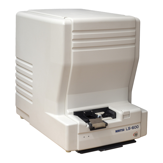
LS-600
Starting Guide
2
This manual covers precautions and other information you need to know before
operating this product.
1.
For your safety
2.
Getting Started
3.
Turing power on/off
4.
Emergency operation
5.
Mastering basic operations
6.
Daily maintenance
7.
How to access the HELP display
8.
Accessories and consumable parts
English
Ver. 1
Advertisement
Table of Contents

Related Manuals for Noritsu LS-600


Summary of Contents for Noritsu LS-600
- Page 1 LS-600 Starting Guide This manual covers precautions and other information you need to know before operating this product. For your safety Getting Started Turing power on/off Emergency operation Mastering basic operations Daily maintenance How to access the HELP display Accessories and consumable parts English Ver.
- Page 2 This page is intentionally blank.
- Page 3 Preface We greatly appreciate your purchase of this product. Before using this product, read the manual carefully, and make sure that you understand the procedure described. Be sure to store the paper manual near the product so it can be referred to immediately should you have questions about operation or should any problems arise.
- Page 4 Microsoft, MS-DOS and Windows are registered trademarks of Microsoft Corporation in the United States and/or other countries. "UNLHA(32).DLL" is free softtware published by Micco. DIGITAL ICE is a trademark of Kodak. This software is based in part on the work of the Independent JPEG Group. Other product and company names mentioned herein may be the trademarks of their respective owners.
-
Page 5: Explanation Of Manual
Explanation of manual Manual types/contents The following manuals are supplied with this product. Before starting operation, read the EZ Controller Operator's Manual to understand how to print from films and how to save images from films. Manual type Main contents Specifications ï... -
Page 6: Symbols Used In This Manual
Manual type Main contents Operator's Manual " Available functions on each display This section explains available functions on each display. " Configuring initial settings This section explains settings that are required to be configured before you use this product. " Configuring settings of the scanning method This section explains settings for scanning films such as image correction, frame advance and frame number settings. - Page 7 The symbols shown below are used in this manual. Confirm the meaning of each of them before reading the manual. This is called the alert symbol. Text following this symbol contains particularly important information concerning safety. Be sure to heed this information. This symbol is used in conjunction with the words DANGER, WARNING and CAUTION, according to the possible degree of injury to people or damage to physical property.
-
Page 8: Table Of Contents
TABLE OF CONTENTS Preface Explanation of manual ........................... iii Manual types/contents ........................iii Symbols used in this manual ......................iv 1. For your safety Description of warnings (signal words) ................1 - 2 Location of warning labels ....................1 - 3 For your safety ........................ - Page 9 Menu display........................5 - 6 5.3.1 Accessing the Menu display......................5 - 6 5.3.2 Menu display ..........................5 - 7 Scanning 135-type film ....................5 - 9 Scanning IX240 film cartridge ..................5 - 17 Scanning IX240 film taken out of the cartridge ............. 5 - 25 6.
- Page 10 This page is intentionally blank.
-
Page 11: For Your Safety
1. For your safety This section explains general safety precautions. Read these precautions thoroughly and carefully. 1 ñ 1... -
Page 12: Description Of Warnings (Signal Words)
1.1 Description of warnings (signal words) 1.1 Description of warnings (signal words) ï Signal words identify the level of injuries that can potentially occur. ï The signal words used in this manual and found on labels, DANGER, WARNING and CAUTION, are assigned according to the level of potential risk. -
Page 13: Location Of Warning Labels
1.2 Location of warning labels 1.2 Location of warning labels The following shows the locations and types of warning labels on this product. Follow the instructions on the labels carefully in order to operate the product safely and avoid accidents. Do not remove labels. If a label becomes illegible or comes off completely, contact your place of purchase for replacement label using the part number shown. -
Page 14: For Your Safety
1.3 For your safety 1.3 For your safety ! ! ! ! General precautions ï Do not modify, remove or install any non-specified parts without our permission. Doing so may cause severe personal injury or damage this product. It also voids any quality guarantee. ï... - Page 15 1.3 For your safety 1 ñ 5...
-
Page 16: Additional Precautions
1.4 Additional precautions 1.4 Additional precautions ! ! ! ! Precautions in operating the system ï Do not place a vase or a cup containing liquid on this product. Liquid can damage the product. Do not place heavy objects on the product. ï... -
Page 17: Precautions For Handling Films
1.5 Precautions for handling films 1.5 Precautions for handling films This section explains precautions for handling films, or information that you should know before starting operation. ! ! ! ! Precautions for handling films ï When handling a film, be sure to wear clean gloves and prevent the film from being soiled. ï... - Page 18 This page is intentionally blank.
-
Page 19: Getting Started
2. Getting Started This chapter explains contents or precautions you should know before using this product. 2 ñ 1... -
Page 20: Manuals Supplied If A Printer And The Ez Controller Are Connected
2.1 Manuals supplied if a printer and the EZ Controller are connected 2.1 Manuals supplied if a printer and the EZ Controller are connected If the system consists of the EZ Controller, a scanner and a printer, we supply manuals to each of these sections in hard copies, as built-ins (HELP), and on CD-Rs. -
Page 21: Names Of The Components
2.2 Names of the components 2.2 Names of the components This product is a device for scanning images on films. Images on films can be printed or saved to storage media by connecting this product to an output system. 2.2.1 Names and functions of components G088487 Name Functions... - Page 22 2.2 Names of the components Name Functions Transfer switch Selects whether to supply power from household socket or from the connected printer to this product. ï If supplying power from household socket Flip the transfer switch down. Turning on the power supply of the PC starts up this product. Transfer switch ï...
-
Page 23: Processable Films
2.3 Processable films 2.3 Processable films This section explains processable films. 2.3.1 Processable films Images on the following films can be printed. Film type Details Color negative film Negative film processed as color negative Sepia Sepia film processed as color negative Black and white film (orange Black and white negative film processed as color negative. -
Page 24: Problematic Films And Corrective Actions
2.3 Processable films Film type Processable length IX240-type film Film that is not cut into pieces. (One that is cut into pieces is not processable.) ï The following length is required for IX240-type film cut by the optional front edge reshaper or rear edge reshaper. Front edge 120 mm or more Rear edge... - Page 25 2.3 Processable films Symptom Corrective action Badly twisted film If the film is twisted and there is more than one twist when the film is held by one end, twist the film in the opposite direction. If the twist is not rectified, hold the film with your hands so that it dose not twist while it is being inserted into the film carrier.
- Page 26 2.3 Processable films Symptom Corrective action Tape (splicing tape etc.) If tape is attached to the leading or rear end, cut the end perpendicularly, if there is enough is attached to either end space. If there is not enough space, remove it without leaving any gum and making film end of the film.
-
Page 27: Processing An Ix240 Film Cartridge That Cannot Be Scanned
2.3 Processable films Symptom Corrective action Perforations are covered If perforations are covered by tape, remove the tape so as not to damage the perforations. with tape. Remove it thoroughly so that no glue remains. ï This occurs only to 135-type films. - Page 28 This page is intentionally blank.
-
Page 29: Turing Power On/Off
3. Turing power on/off This section explains how to turn the product's power on and off. 3 ñ 1... -
Page 30: Starting Up And Closing Down This Product
3.1 Starting up and closing down this product 3.1 Starting up and closing down this product 3.1.1 Starting up the product There are two methods to start up this product. If starting up the product from the EZ Controller ï For details, see the EZ Controller Starting Guide. If using as a stand-alone scanner Check whether the USB cable is correctly connected. -
Page 31: Emergency Operation
4. Emergency operation This chapter explains how to restart this product when an error occurs, how to turn off the power supply in an emergency and how to take corrective actions for the case that the scanner makes abnormal sounds. 4 ñ... -
Page 32: Restarting The Product Because An Error Occurs
4.1 Emergency operation 4.1 Emergency operation This chapter explains how to restart this product when an error occurs or how to turn off the power supply in an emergency. 4.1.1 Restarting the product because an error occurs Restart the system to take corrective actions for an error by following the steps below. Click the Minimize button to reserve the error or attention. -
Page 33: If The Scanner Makes Abnormal Sounds
4.1 Emergency operation 4.1.3 If the scanner makes abnormal sounds Follow the instructions below if the scanner emits strange sound and that it is necessary to stop scanning immediately. Steps Open the front cover. Scanning stops. Confirm that no film is jammed. Remove jammed film, if any. - Page 34 This page is intentionally blank.
-
Page 35: Mastering Basic Operations
5. Mastering basic operations This section explains procedures about how to access the Scan Setting display or scanning operation. 5 ñ 1... -
Page 36: Scan Setting Display
5.1 Scan Setting display 5.1 Scan Setting display The Scan Setting display is shown when this product is started up separately. Example: Scan Setting display S5200-00-UM01 Name Functions Environment display This is a display where scanning methods settings are configured, such as the image correction, frame feed and frame number. - Page 37 5.1 Scan Setting display Select File→Read→LS-600. Example: Display of Adobe Photoshop S087590 The Scan Setting display is shown. 5 ñ 3...
-
Page 38: Environment Display
ï For details, see the EZ Controller Starting Guide, Accessing the scanner and printer screens. If accessing the display from a stand-alone scanner Start image editing software such as Adobe Photoshop. Select File→Read→LS-600. Example: Display of Adobe Photoshop S087590 The Scan Setting display is shown. -
Page 39: Environment Display
5.2 Environment display Click the Environment tab. S5200-00-UM01 The Environment display is shown. 5.2.2 Environment display S5201-00-UM01 Name Functions Correction tab Image correction settings can be configured on this display. ☞ ï For details, see 3.1 Configuring image correction settings [Environment: Correction tab] in the Operator's Manual Film Carrier tab Frame feed and frame number settings can be configured on this display. -
Page 40: Menu Display
If accessing the display from a stand-alone scanner There are two methods to access the Menu display from a stand-alone scanner. Step 1 Click Start on the Windows screen →Programs→ LS-600. The Menu display is shown. Step 2 Start image editing software such as Adobe Photoshop. -
Page 41: Menu Display
5.3 Menu display Click the Menu tab. S5200-00-UM01 The Menu display is shown. 5.3.2 Menu display S5202-00-UM03 Name Functions Close Down Checks Allows you to start the Close Down Checks. ☞ ï For details, see 6.2 Weekly Checks. Scanner Calibration Allows you to perform Light Source Update. - Page 42 5.3 Menu display Name Functions Input Check Allows you to confirm the status of switches and sensors. ☞ ï For details, see 5.3.1 Confirming switch and sensor status [Input Check] in the Operator's Manual Output Check Allows you to confirm operation of parts such as motors. ☞...
-
Page 43: Scanning 135-Type Film
Confirm the power supply of the flatbed scanner is on. Access the Scan Setting display. Accessing the Scan Setting display is necessary for scanning. Start image editing software such as Adobe Photoshop. Select File→Read→LS-600. Example: Display of Adobe Photoshop S087590 The Scan Setting display is shown. - Page 44 5.4 Scanning 135-type film Item Explanation Scanning status Displays the status of the scanner. ï Scanner unit is not connected. The PC and the scanner are not connected. The scanner power is off or the USB cable is not connected. ï...
- Page 45 5.4 Scanning 135-type film Item Explanation Resolution Select the resolution for the film to scan by clicking The source size and the image size at the selected resolution are shown. ï LOW: Select this if making 89 mm × 127 mm prints using a 300 dpi printer, for example.
- Page 46 5.4 Scanning 135-type film Click Scan. S5200-00-UM01 Put on clean gloves. If you have the film cleaner (option), pass the film through the film cleaner. Dust can be removed from the film by passing the film through the optional film cleaner. Example: Film cleaner G088496...
- Page 47 5.4 Scanning 135-type film ☞ ï For details about how to use the Operator's Manual, see 7.1 Accessing the HELP display. Example: Judgment Display S5041-00-UM01 Press the F12 key ( ) to cancel the operation. Then, follow the message displayed on the monitor. This completes the scanning operation if AUTO is selected in PJP/AUTO Switch on the Correction tab of the Environment display.
- Page 48 5.4 Scanning 135-type film Select Print Image Fine Adjustment with the ←, →, ↑ and ↓ keys, then press the Enter key Example: Functions display S087599 Adjust the image area with the F10 ( ) and F9 ( ) keys. Explanation F10 key ( The image moves to the right.
- Page 49 5.4 Scanning 135-type film ☞ ï For details, see 4.1.4 Corrections of contrast and sharpness [DSA], in the Operator's Manual. ☞ ï For details about how to use the Operator's Manual, see 7.1 Accessing the HELP display. Example: DSA display S087603 ï...
- Page 50 5.4 Scanning 135-type film After you configure the settings of color and density, click START. If you do not have any more images to output, go to the next step. Example: Judgment Display S5041-00-UM01 Scanned image is displayed onscreen. Click Close on the Scan Setting display. Example: Scan Setting display S5200-00-UM01 Save the image that is displayed onscreen to any destination using image editing software...
-
Page 51: Scanning Ix240 Film Cartridge
Confirm the power supply of the flatbed scanner is on. Access the Scan Setting display. Accessing the Scan Setting display is necessary for scanning. Start image editing software such as Adobe Photoshop. Select File→Read→LS-600. Example: Display of Adobe Photoshop S087590 The Scan Setting display is shown. - Page 52 5.5 Scanning IX240 film cartridge Item Explanation Scanning status Displays the status of the scanner. ï Scanner unit is not connected. The PC and the scanner are not connected. The scanner power is off or the USB cable is not connected. ï...
- Page 53 5.5 Scanning IX240 film cartridge Item Explanation Resolution Select the resolution for the film to scan by clicking The source size and the image size at the selected resolution are shown. ï LOW: Select this if making 89 mm × 127 mm prints using a 300 dpi printer, for example.
- Page 54 5.5 Scanning IX240 film cartridge Click Scan. S5200-00-UM01 Put on clean gloves. Insert the IX240 film cartridge. Press the eject button in the direction shown by the arrow to raise the cartridge holder. Eject button Cartridge holder G088498 Adapt the IX240 film cartridge to the holder and lay the holder. Cartridge holder G088499 The IX240 film is fed into the film feed unit and the scanning process starts.
- Page 55 5.5 Scanning IX240 film cartridge After scanning finishes, the Judgement Display is shown. The Judgement Display is shown only when PJP is selected in PJP/AUTO Switch on the Correction tab of the Environment display. ☞ For details about the Judgement Display, see 4.1 Configuring color and density settings in the Operator's Manual.
- Page 56 5.5 Scanning IX240 film cartridge Keyboard operation Press the F1 key ( ) to access the Functions display. Select Print Image Fine Adjustment with the ←, →, ↑ and ↓ keys, then press the Enter key Example: Functions display S087599 Adjust the image area with the F10 ( ) and F9 ( ) keys.
- Page 57 5.5 Scanning IX240 film cartridge Click the DSA button and adjust Contrast, Sharpness and Chroma. Example: Judgment Display DSA button G087602 The DSA display is shown. Correct the image if necessary. ☞ ï For details, see 4.1.4 Corrections of contrast and sharpness [DSA], in the Operator's Manual. ☞...
- Page 58 5.5 Scanning IX240 film cartridge Click START. Example: Judgment Display S5041-00-UM01 Corrects color and density of other images. If there are more images, the next page is displayed. After you configure the settings of color and density, click START. If you do not have any more images to output, go to the next step. Example: Judgment Display S5041-00-UM01 Scanned image is displayed onscreen.
-
Page 59: Scanning Ix240 Film Taken Out Of The Cartridge
Confirm the power supply of the flatbed scanner is on. Access the Scan Setting display. Accessing the Scan Setting display is necessary for scanning. Start image editing software such as Adobe Photoshop. Select File→Read→LS-600. Example: Display of Adobe Photoshop S087590 The Scan Setting display is shown. - Page 60 5.6 Scanning IX240 film taken out of the cartridge Item Explanation Scanning status Displays the status of the scanner. ï Scanner unit is not connected. The PC and the scanner are not connected. The scanner power is off or the USB cable is not connected.
- Page 61 5.6 Scanning IX240 film taken out of the cartridge Item Explanation Resolution Select the resolution for the film to scan by clicking The source size and the image size at the selected resolution are shown. ï LOW: Select this if making 89 mm × 127 mm prints using a 300 dpi printer, for example.
- Page 62 5.6 Scanning IX240 film taken out of the cartridge Click Scan. S5200-00-UM01 Put on clean gloves. Press the eject button to raise the cartridge holder. Eject button Cartridge holder G071842 Attach the IX240 film adapter. IX240 film adapter G071851 5 ñ 28...
- Page 63 5.6 Scanning IX240 film taken out of the cartridge Lay the IX240 film adapter down. IX240 film adapter G071852 Insert IX240 film strip taken out of the cartridge into the film slot as shown below. IX240 film taken out of its cartridge G071853 The IX240 film is fed into the film feed unit and the scanning process starts.
- Page 64 5.6 Scanning IX240 film taken out of the cartridge Click the image to correct color and density. Right-click on an image to skip it. Then it will not be scanned. Example: Judgment Display Click here. S5041-00-UM01 Confirm the image area of the scanned image. For images whose position is not easy to adjust, such as a night scene, you can use the frame stop position adjustment function.
- Page 65 5.6 Scanning IX240 film taken out of the cartridge Adjust the image area with the F10 ( ) and F9 ( ) keys. Explanation F10 key ( The image moves to the right. F9 key ( The image moves to the left. Click the Color and density correction button to correct color and density.
- Page 66 5.6 Scanning IX240 film taken out of the cartridge Example: DSA display S087603 ï The DSA display can also be accessed from the Functions display. Example: Functions display S087599 Move the frame to the next image by pressing the keys ←, →, ↑ or ↓, then perform Step 11 to Step 13.
- Page 67 5.6 Scanning IX240 film taken out of the cartridge Click Close on the Scan Setting display. Example: Scan Setting display S5200-00-UM01 Save the image that is displayed onscreen to any destination using image editing software such as Adobe Photoshop. After saving the image, correct it as necessary. This completes scanning IX240 film taken out of the cartridge.
- Page 68 This page is intentionally blank.
-
Page 69: Daily Maintenance
6. Daily maintenance This chapter explains the necessary maintenance for maintaining the quality of this product. 6 ñ 1... -
Page 70: Introduction Of Daily Maintenance
6.1 Introduction of daily maintenance 6.1 Introduction of daily maintenance This section shows maintenance items and their timing. 6.1.1 Maintenance items and timing Timing Part Operation Reference ☞ Weekly Checks Film feed unit (cleaning the film feed section) Cleaning 6.2.1 ï... -
Page 71: Weekly Checks
6.2 Weekly Checks 6.2 Weekly Checks Access the Close Down Checks display after finishing all processes of the day. Follow the instructions on the display to perform the checks. ï If film jams frequently occur or the film stop position is unstable, clean the film feed section according to need. ☞... - Page 72 6.2 Weekly Checks Click Execute. Set the Cleaning Leader. is shown. Put on clean gloves. Insert the 240 lane cleaning leader. MPORTANT ï Be sure to clean both the 135 and the 240 lanes. Press the eject button. The cartridge holder will rise. Eject button Cartridge holder G071842...
- Page 73 6.2 Weekly Checks Lay the IX240 film adapter down. IX240 film adapter G071852 Insert the supplied cleaning leader for the 240 lane into the film inserting slot. 240 cleaning leader G073165 Cleaning operation is automatically performed, and the leader is output. Put the cleaning leader and the IX240 film adaptor back.
- Page 74 6.2 Weekly Checks Put the cleaning leader back. To store the cleaning leader, put the cleaning leader in a nylon bag, then put it in the cleaning leader case. Cleaning leaders Cleaning leader case G088639 This completes cleaning the film feed section. 6 ñ...
-
Page 75: Monthly Checks
6.3 Monthly Checks 6.3 Monthly Checks 6.3.1 Cleaning the scanner dust-proof glass Conditions Perform this maintenance operation with the power on. Requirements ï Blower brush Select the 240 lane of the film feed unit. MPORTANT ï If the 135 lane of the film advance unit is selected, it is necessary to select the 240 lane by following the procedure below. -
Page 76: Cleaning The 135 Rewinding Unit
6.3 Monthly Checks MPORTANT ï Do not use alcohol to clean. It may adversely affect print quality. Scanner dust-proof glass G082964 Close the side cover (left) and front cover. If cleaning the 135 rewinding unit, it is not necessary to close the side cover (left) and front cover. This completes cleaning the scanner dust-proof glass. - Page 77 6.3 Monthly Checks Open the front cover and side cover (left). Front cover Side cover (left) G087613 Loosen a knob screw of the 135 rewinding unit, and remove the 135 rewinding unit. Knob screw 135 rewinding unit G071858 Open the rewinding guide and wipe the inside of the 135 rewinding unit with firmly squeezed damp cloth.
- Page 78 6.3 Monthly Checks ï After wiping each part using firmly-squeezed damp cloth, completely dry the parts. Do not insert film unless the cleaned parts are completely dry. Inside of the 135 rewinding unit Inside of the 135 rewinding unit G073185 Reattach the 135 rewinding unit.
-
Page 79: Cleaning Each Roller And The Film Path Of The Film Feed Unit
6.3 Monthly Checks Close the side cover (left) and front cover. If cleaning each roller of the film advance unit and film path, it is not necessary to close the side cover (left) and front cover. This completes cleaning the 135 rewinding unit. 6.3.3 Cleaning each roller and the film path of the film feed unit Conditions Perform this maintenance operation with the power on. - Page 80 6.3 Monthly Checks Release the lock to open the film advance top cover. Lock (Pressing it releases the lock.) G071848 Wipe off each roller and the film path with firmly-squeezed damp cloth. MPORTANT ï Do not touch the film path or sensors with your bare hands. After wiping each part, dry it completely.
-
Page 81: Cleaning Each Brush Of The Film Feed Unit
6.3 Monthly Checks Close the film advance top cover, side cover (left) and front cover. If cleaning each brush of the film advance unit, it is not necessary to close the film advance top cover, side cover (left) and front cover. This completes cleaning each roller, and the film path of the film feed unit. -
Page 82: Cleaning The Magnetic Head
6.3 Monthly Checks Release the lock to open the film advance top cover. Lock (Pressing it releases the lock.) G071848 Clean each brush using a blower brush. MPORTANT ï Gently handle each brush to prevent damaging it. Brushes on the 240 lane Brushes on the 135 lane G071855 Close the film advance top cover, side cover (left) and front cover. - Page 83 6.3 Monthly Checks Select the 240 lane of the film feed unit. MPORTANT ï If the 135 lane of the film advance unit is selected, it is necessary to select the 240 lane by following the procedure below. If the 135 lane is selected, the film advance top cover cannot be opened fully. Slightly open the front cover, then close it.
-
Page 84: Cleaning The Film Inserting Slot Of The 240 Rewinding Box
6.3 Monthly Checks Clean the magnetic head by wiping it with a cotton swab dipped in isopropyl alcohol. MPORTANT ï Isopropyl alcohol is flammable. Keep it away from open flame, and carefully follow the instructions on labels on the chemical bottles. ï... -
Page 85: Cleaning The Air Filter
6.3 Monthly Checks Open the front cover and side cover (left). Front cover Side cover (left) G087613 Put on clean gloves. Release the lock to open the film advance top cover. Lock (Pressing it releases the lock.) G071848 Clean the film inserting slot of the 240 rewinding box using a blower brush. Film inserting slot G073170 Close the film advance top cover, side cover (left) and front cover. - Page 86 6.3 Monthly Checks If dust accumulates on the air filter, air intake and exhaust cannot be performed normally, and that adversely affects the product. Conditions Perform this maintenance operation with the power on. Requirements ï Vacuum cleaner Procedure Remove the air filter and clean it. Air filter G082938 Vacuum dust from the dust accumulated surface using a vacuum cleaner.
-
Page 87: How To Access The Help Display
7. How to access the HELP display You can view the built-in manuals (HELP) on the display. This chapter explains how to access the HELP display. S088497 7 ñ 1... -
Page 88: Accessing The Help Display
7.1 Accessing the HELP display 7.1 Accessing the HELP display 7.1.1 Accessing the HELP display There are three ways to access the HELP display of this product. ! ! ! ! Accessing from the icon on the display Click the HELP icon on the display. Example: Some HELP icons are displayed. -
Page 89: Accessing The Help Display
7.1 Accessing the HELP display Example: Menu display S5202-00-UM03 The Help display is shown. Example: HELP display S088497 The numbers in the table below correspond to those in the illustration above. Item Explanation HELP functions, How to use Explains how to use HELP, such as the explanation of the buttons in the HELP HELP display and how to search. -
Page 90: Accessing The Help Display From The Error/Attention Display
7.1 Accessing the HELP display Item Explanation Bookmark The contents or the search results are displayed here. Selecting the desired item in this bookmark shows its explanation. To display all the information of the table of contents, click the + mark. Contents This completes accessing the HELP display . -
Page 91: Closing The Help Display
7.1 Accessing the HELP display The corrective actions for the error or attention message is shown. S088483 This completes accessing the HELP display from the Error/Attention display. 7.1.3 Closing the HELP display Click × on the HELP display. S088483 The HELP display is closed. 7.1.4 Hiding the HELP display The HELP display hides other displays. - Page 92 7.1 Accessing the HELP display You can hide the HELP display by clicking the Minimize button. The button is in the upper right corner of the HELP display. Minimize S088497 If the EZ Controller is used To access the HELP display again, click the HELP icon on the display. G087850 This completes hiding the HELP display.
-
Page 93: Accessories And Consumable Parts
8. Accessories and consumable parts This chapter explains part numbers of accessories and consumable parts. 8 ñ 1... - Page 94 8.1 Accessories and consumable parts 8.1 Accessories and consumable parts ï Pay attention to avoid electric shock, burn and injury. For replacing parts that are not explained in the Operator's Manuals, contact your place of purchase and leave them to service personnel. This section explains the part numbers of consumable parts, supplied parts and others used for daily maintenance.
Need help?
Do you have a question about the LS-600 and is the answer not in the manual?
Questions and answers