Table of Contents
Advertisement
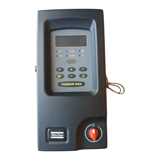
Tensor DS Drive
Quick Guide
SAFETY INSTRUCTIONS
When using electric products, basic precautions
should be followed:
THIS EQUIPMENT MUST BE EARTH GROUNDED.
Always disconnect the equipment from the mains,
by pulling the plug, before opening it for installation,
service etc.
Do not use this product near water.
Advertisement
Table of Contents

Related Manuals for Atlas Copco Tensor

Summary of Contents for Atlas Copco Tensor
- Page 1 Tensor DS Drive Quick Guide SAFETY INSTRUCTIONS When using electric products, basic precautions should be followed: THIS EQUIPMENT MUST BE EARTH GROUNDED. Always disconnect the equipment from the mains, by pulling the plug, before opening it for installation, service etc.
- Page 2 INSTALLATION HARDWARE Figure 1 Figure 2 1. Open the lock mechanism (see figure 1) 2. Open the DS Drive by pulling it (see figure 2) 3. Connect the tool cable, power cable etc. (see figure 3) 4. Check so that the GFI is switched on 5.
- Page 3 DISPLAY/KEY PAD Display 2. OK LED 3. n x OK LED 4. Lock LED 5. NOK LED 6. Alarm LED Graph LED 8. IRDA 9. Function button 10. AutoSet button 11. Plus button (+) 12. Question mark button 13. Enter key button 14.
- Page 4 KEY PAD FUNCTIONS AutoSet Programming: The AutoSet Programming feature allows the DS Drive to recognise a joint’s stiffness and adjust the tool for maximum performance for that particular joint accordingly. 1. Press the AUTOSET button once and ASEt/F1 appears on the display. 2.
- Page 5 Fine – Tuning Final Target This enables personnel to fine the final target. 1. Press the FUNCTION button once and Ft/F2 appears on the display. 2. Adjust final torque target by pressing the +/- buttons. (The torque can be adjusted a maximum of +15% or –5% from the original final target).
- Page 6 Motor Tuning This function will optimize the performance of the motor and minimize losses, i.e. after service. Press the FUNCTION button three times and tool/F4 appears on the display. 2. Press the ENTER button until the display starts to flash. 3.
- Page 7 FULL PROGRAMMING Tightening strategy You can select strategy choices as shown. Soft Start Time In order to facilitate screw engagement the tool starts by turning at a very low speed during the soft start time. Targets At First Target the tool will shift from Step 1 Speed to Step 2 Speed .
- Page 8 RUNDOWN MONITORING Rundown Monitoring is a function to detect bad rundowns. The angle in both first and second step is monitored. See graph below. Cycle Start Cycle Start is the torque limit from which the angle is measured. The maximum limit for Cycle Start is First Target.
- Page 9 HIGH SPEED RUNDOWN High Speed Rundown allows the tool to make the rundown at a higher speed than Step 1 Speed. The function is used when a fastener has a long rundown angle and there is a risk for overshooting when the joint is hard. SELF TAP The Self Tap function is used for thread forming screws and other fasteners with a torque pulse in the beginning of the...
- Page 10 CONFIGURATION The Configuration window has three different subgroups: System Administration, I/O Configuration (containing I/O Setup and RE-Alarm Setup) and Tool Service Setup. 1. In System Administration you define the operator interface. 2. In I/O Configuration – I/O you define how to use the different input and output connections on the DS Drive.
- Page 11 INPUTS AND RELAYS Figure 1 shows how to connect in order to obtain a signal on one of the digital inputs. The power source can either be built in 24 VDC or an external power source. Figure 2 shows how to connect to obtain OK and NOK signals using relay outputs RE1 &...
- Page 12 TOOL SERVICE SETUP In the Tool Service Setup window you can see information about last service date and number of tightenings after service. It is also the start window to set the service date in the tool and the service interval. You activate the service indicator by changing the pull down menu to ON.
- Page 13 ERROR CODES Error codes are displayed with four characters, beginning with an E. All error codes are found in the DS Drive Manual. Group 0 Rundown failures, E000-E031 Group 1 Event related errors, E100-E131 Group 2 User input error, E200-E231 Group 4 Communication errors, E400-E431 Group 5...
- Page 14 ERROR CODES Ack- Error now- Help code Description ledge What to do? text IO device not E403 Check cables and restart drive. responding Multiple devices E408 of same type on Yes You are only allowed to use one. IO bus Multiple selectors E409 on IO bus...
Need help?
Do you have a question about the Tensor and is the answer not in the manual?
Questions and answers