
Related Manuals for LigoWave LigoPTP 24 Series

Summary of Contents for LigoWave LigoPTP 24 Series
- Page 1 LigoPTP 24 Technical Description & Configuration Guide Revision 1.0 December 9, 2009 Copyright © 2009 LigoWave www.ligowave.com...
-
Page 2: Copyright
This user‟s guide and the software described in it are copyrighted with all rights reserved. No part of this publication may be reproduced, transmitted, transcribed, stored in a retrieval system, or translated into any language in any form by any means without the written permission of LigoWave. Notice LigoWave reserves the right to change specifications without prior notice. -
Page 3: Table Of Contents
User Configuration ........................41 Names Configuration ........................42 Other Configuration ........................43 Upgrade Software ......................... 44 IP Configuration Window ........................44 Ethernet Management Port IP Configuration ................44 IP Services ............................ 45 Static Route Configuration ......................45 LigoWave Page 3... - Page 4 Uploading File via Serial Port (Xmodem) ..................84 RSSI PORT ............................86 PINOUTS ............................... 87 18-pin Connector........................... 87 Twin BNC Connector ........................87 Sealed RJ-45 Socket ........................88 AVAILABLE ACCESSORIES....................... 89 Other Available Accessories ......................92 APPENDIX ............................93 List of Abbreviations ........................... 93 LigoWave Page 4...
-
Page 5: Overview
Technical Description & Configuration Guide Overview Overview This document briefly describes the LigoPTP 24 series Full Outdoor Unit (FODU) covering the built-in management system, configuration functionality, hardware features, etc. LigoPTP 24 Full Outdoor Units LigoPTP 24 product family is the new next generation product line which is targeting growing demands for data transmission over microwave radio. -
Page 6: Interfaces/Management
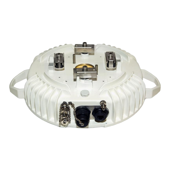
Twin BNC connector of the unit enables terminal access into the unit BNC connector provides AGC voltage signal to assist unit alignment Web, Telnet and SNMP are available as NMS interfaces into the unit Figure 2 – LigoPTP 24 FODU Connectors LigoWave Page 6... -
Page 7: Radio Parameters
ACM (Adaptive Coding and Modulation), hitless ACM opens whole lot of new possibilities depending on network designers strategy ATCP, Automatic Transmitter Power Control, for increased deployment density capability. Very high flexibility allows configuring the system to various channel bandwidths, modulation schemes and capacity settings LigoWave Page 7... -
Page 8: Application Examples
Extends network to non line-of-sight locations; Ideal for crossing mountains and interconnecting Ethernet networks; Low power consumption allows the use of battery backed alternative power sources like solar panel and small wind turbine for off-grid remote sites. LigoWave Page 8... -
Page 9: Metro Ethernet And Mesh Networks With Ligoptp 24 Fodu
Full Outdoor solution with Power over Ethernet Plus is efficient for All Outdoor Base station connectivity; Last Mile Access for demanding power user and many other applications; Gigabit Ethernet backhaul can be supported with LigoWave products. LigoWave Page 9... -
Page 10: Technical Ligoptp 24 Specification
Gain 35.0 dBi 3dB Beamwidth 2.9° VSWR/Return Loss 1.43:1 / 15 dB Size (Diameter) 1 ft. Weight 2.3 kg Operational: 112 Wind load Operational: 112 mph Survival: 155 mph PTP 24-2: Gain 40.3 dBi 3dB Beamwidth 1.7° LigoWave Page 10... - Page 11 64.8 Mbps at 123.6 Mbps at 184.6 Mbps -83 dBm -76 dBm -74 dBm -73 dBm 32APSK+wide at 34.6 Mbps at 76.2 Mbps at 154.6 Mbps at 212 Mbps *Preliminary data - actual data may vary slightly. LigoWave Page 11...
-
Page 12: Cable Requirements
Cat. 5e UTP or better cable is required for power supply, management of device and data traffic. LigoPTP 24 FODU can be used with any LigoWave additionally provided Power over Ethernet sourcing equipment (provided power >25 W). Used voltage is between 36–57 V DC, though the nominal voltage is 48 V, over two of the four available pairs on a Cat. -
Page 13: Labeling
Note that frequency range is set from the central frequency of the first 7 MHz channel to the central frequency of the last 7 MHz channel (see below) Figure 6 – Frequency range of the LigoPTP 24 FODU The Figure explains Tx frequency range of low side LigoPTP 24 FODU radio. LigoWave Page 13... -
Page 14: Configuration And Management
Be aware that length of RJ45 connectors may vary! This is the reason why weatherproof connector enclosure has room for longest possible RJ45 connector. This instruction will show you how to correctly assemble weathered connector and have best possible connection of RJ45 connector with socket. LigoWave Page 14... -
Page 15: Ethernet Management Connection Configuration
8. RJ45 connector position if it is aligned during weatherproof connector assembly „in-place”. Ethernet Management Connection Configuration Before you proceed to initial link setup with Web GUI, you must perform Ethernet connection configuration by following these steps: LigoWave Page 15... - Page 16 Start Settings Control panel Network connections) Find „Local Area Connection‟, click right mouse button on it and choose „Properties‟ Step 2. Click on „Internet Protocol (TCP/IP)‟ from the list in the dialog box and then click on Step 3. „Properties‟ LigoWave Page 16...
- Page 17 Step 4. In the dialog box enter the following values (so that your PC is in the same subnet as default LigoPTP 24 addresses): Now you are ready to connect to Web GUI or establish Telnet connection. LigoWave Page 17...
-
Page 18: Power Over Ethernet Injection
LigoPTP 24 FODU. It is possible to use passive injectors, utilizing spare leads. Refer to chapter Pinouts for detailed information on pinouts. Power over Ethernet injector can be purchased from LigoWave as an optional accessory. Below is an example of a passive and active Power over Ethernet injector, as well as its application scheme. -
Page 19: Termination Panel For 4 E1 And With Power Injector (Ligoptp-Tp4)
Dimensions (HxWxD): 44 x 482.6 x 54 mm; Weight: 0.6 kg. Connection with Web Interface It is recommended to use the following web-browsers (and all later versions): IE v. 6.0 Mozilla Firefox v. 2.0.0.11 Safari v. 3.0 LigoWave Page 19... - Page 20 If the WEB page is not shown correctly, try purging browser cookies, cache and offline data and restarting the browser. All the commands, which will be executed from the WEB GUI, will be translated to CLI commands and will be executed as in CLI. LigoWave Page 20...
-
Page 21: Interface Description
(only in some places); no value data (N/D). If the entry is highlighted in yellow, this means warning condition. If the value place reads „N/D‟, this means „No Data‟. If the value place reads „N/A‟, this means „Not Available‟. LigoWave Page 21... -
Page 22: Command Execution
Rollback will activate only if you lose connection to WEB interface of LigoPTP 24 FODU after configuration changes applied, and reverting process will take approx. 3 minutes. LigoWave Page 22... -
Page 23: Initial Configuration With Web Gui
Protocol (TCP/IP) Properties): IP address 192.168.205.1; netmask 255.255.255.0; everything else is blank. LigoPTP 24 FODU must be powered up using dedicated Power over Ethernet injector with load power at least 25W. See Chapter 2.2.4 for details. LigoWave Page 23... - Page 24 To start simple configuration process, you must proceed with the configuration wizard which will set up the main parameters of the link to make it work. So, the first step is to go to „Configuration Configuration wizard‟ as shown below in the Figure 17 – Starting Configuration Wizard. LigoWave Page 24...
- Page 25 (guest or admin) and user password. It is highly recommended to name the system after its geographical location. By default, system name is „LigoPTP‟. Figure 18 – STEP 1. Defining System Name and Passwords for “guest” and “admin” Accounts LigoWave Page 25...
- Page 26 Clear cfg file before the new settings will take place – resetting or keeping all the other parameters, not mentioned here, after configuration execution Set local machine time – uses the time of your laptop Write this configuration into cfg file – configuration is automatically written in configuration file LigoWave Page 26...
-
Page 27: Command Prompt Interface
The usage of each command is displayed if the command followed by the “?” (or any unrecognizable string) is entered, e.g., radio ? The management system is automatically restarted if it freezes. This is performed by the watchdog timer. Restarting of the management system does not affect (interrupt) the E1/Ethernet traffic. LigoWave Page 27... -
Page 28: Rs-232 Serial Management Port
Windows version), proceed as described below. Connect the PC to the RS232 serial port by means of “straight through” or modem serial Step 1. cable (null-cable). Run “Hyper Terminal” program. Step 2. Step 3. Make a New connection and enter connection name. LigoWave Page 28... - Page 29 Set port settings (bits per second: 19200, data bits: 8, parity: none, stop bits: 1, data flow control: none). Step 6. Press OK Step 7. Press Enter. Password is disabled by default. If successfully connected, the prompt should appear as in the picture below. LigoWave Page 29...
-
Page 30: Telnet Connection
If the Ethernet management connection is configured properly, you will see a window similar to the one shown below, where you will be asked to enter login and password. Default login is identical to WEB login name: user name – admin password – changeme LigoWave Page 30... -
Page 31: Initial Configuration With Command Prompt
Remote IP address with the command net ip remaddr <remaddr>, if it is necessary; Step 3. Save settings with the command cfg write; restarting with the command system reset; Step 4. Check the settings made, modem and radio status with the commands status, modem status and radio status respectively. LigoWave Page 31... -
Page 32: Status Window
Rx level (or RSL) at both ends must not differ significantly from the previously calculated value. Modulation indicates which modulation mode is used. For better operation the same modulation must be set at both ends. Radial MSE is explained below in the chapter Radial MSE. LigoWave Page 32... - Page 33 Modem temperature – shows the temperature on modem in degrees by Celsius (command line - diagnostics or status); Input voltage – shows the input voltage of PSU in volts (command line - diagnostics); Current – shows the current of PSU in amperes (command line - diagnostics); LigoWave Page 33...
-
Page 34: Radial Mse
~ 4.010 for "wide" option ~ 1.010 As long as LDPC stress value is under the specified thresholds, the amount of errors (and BER itself) on the output of LDPC remains at zero level. LigoWave Page 34... -
Page 35: Detailed Configuration In Web
LigoPTP 24 FODU. If “Rollback on is selected, configuration will be reverted in case of erroneous configuration changes applied. Pressing Execute for both applies changes made to the corresponding section both for local and remote side LigoPTP 24 FODUs. LigoWave Page 35... -
Page 36: Atpc Configuration
LigoPTP 24 FODU. If Rollback on is selected, configuration will be reverted in case of erroneous configuration changes applied. Pressing Execute for both applies changes made to the corresponding section both for local and remote side LigoPTP 24 FODUs. ATPC Algorithm LigoWave Page 36... -
Page 37: Modem Configuration
LigoPTP 24 FODU adjusts the transmitter power in accordance with the algorithm shown below. Figure 25 – ATPC algorithm Modem Configuration Modem data status – shows if management CPU was able to read data from modem; LigoWave Page 37... - Page 38 For example, when bad weather has decreased the channel capacity of a link, ACM maintains high- priority services – such as E1 channels – with full bandwidth capacity while adapting the bandwidth capacity of low- and mid-priority services such as Internet browsing (see figure below). Figure 26 – ACM bandwidth capacity adaptation LigoWave Page 38...
- Page 39 Most of the time the system would support a 100Mbps Ethernet connection instead of a 34 Mbps connection. The system automatically monitored the link conditions and changed the capacity without interrupting the data transmission (hitless changes), as shown in figure below. Figure 27 – Link availability and classes of services LigoWave Page 39...
-
Page 40: Loopback Configuration
FODU returned - in case of error or incorrectly entered parameter value, or other problems on the whole page – the info message is being shown here. Otherwise it says “Ok”. Additional radio and modem configuration commands in Telnet/serial interface is provided in the table below: LigoWave Page 40... -
Page 41: System Configuration
– Enter new password (length: 4..30 characters) – allows entering preferable „guest‟ account password and enabling the account. By default guest account is disabled. Maximal length of the password cannot exceed 30 symbols. Guest account has only monitoring privileges. The following Web GUI sections are available: LigoWave Page 41... -
Page 42: Names Configuration
FODU name (Max length: 17 characters) – allows entering preferable system name. It is recommended to name the system after its geographic location. Maximum length of the user name cannot exceed 17 symbols. Default name is „LigoPTP (command line – system name <name>); LigoWave Page 42... -
Page 43: Other Configuration
– removes the alias specified by the argument; clear – removes all the user aliases. show – displays all available commands; System commands [show|help] help – displays available help messages for all commands. LigoWave Page 43... -
Page 44: Upgrade Software
Ethernet MAC address – shows the MAC address of LigoPTP 24 FODU you are currently logged in (command line – net mac); Remote IP Address – shows IP address of remote (far-end) LigoPTP 24 FODU to ensure communication between link sides (command line – net ip remaddr <remaddr>); LigoWave Page 44... -
Page 45: Ip Services
Additional network configuration commands in Telnet/serial interface: Command Description Net ping <ip> This command is for troubleshooting purposes to verify the service channel connectivity, - it sends a special packet to the specified address and then waits for a reply. LigoWave Page 45... - Page 46 In “MS Windows” go to “Control panel Network Connections”. In LAN “Properties” find Step 3. “Internet Protocol TCP/IP” and click on its “Properties” (detailed description is in Chapter Ethernet Management Connection Configuration. Configuration of LAN Ethernet port must be as follows: LigoWave Page 46...
-
Page 47: Ethernet Configuration
Rx – shows if regress activity is allowed on Mng port; Tx – shows if egress activity is allowed on Mng port; Bandwidth limit – shows if Mng port is using bandwidth limiting. If not - 'Full' is being shown. LigoWave Page 47... -
Page 48: Ethernet Configuration
802.1Q VLAN – enables support of 802.1Q VLAN (command line – ethernet vlan [enable | disable]); Management VLAN ID – allows specifying Management VLAN ID. When already configured, shows current Management VLAN ID (command line – ethernet vlan <VLAN ID> management); LigoWave Page 48... -
Page 49: Ethernet Switch Port Status And Settings
Ethernet Switch Port Status and Settings Switch port 1 (LAN) is connected to LAN interface. Switch port 2 (WAN) is connected to WAN interface, modem and radio part. Switch port 3 (Mng) is connected to LAN Management CPU. LigoWave Page 49... -
Page 50: Ethernet Switch Block (Functional) Diagram
When using VLANs (Figure 4.7), it is necessary to use external switches (Switch 3 and Switch 4). These switches add/remove VLAN tags per port basis. Thus, management data and user data have different VLAN tags and are logically separated. LigoWave Page 50... - Page 51 VLAN tags for packets outgoing from port 3. Additionally, VLAN tag is removed at port 3 of Switch 1 and Switch 2. VLAN A is the Trunk type VLAN with port 1 & 2 membership. VLAN B is the Management type VLAN with port 1 & 2 & 3 membership. LigoWave Page 51...
- Page 52 VLAN tagging already must be configured on the switch and known to you; otherwise, incorrect VLAN configuration may disable access to management port. 3) Set preferable VLAN configuration in “VLAN configuration” of local link side LigoPTP 24 FODU Web management. LigoWave Page 52...
- Page 53 Technical Description & Configuration Guide Detailed Configuration in Web Examples of VLAN usage: Figure 34 – VLAN configuration with VLAN tag encapsulation on the ISP side Figure 35 – VLAN configuration with „Access‟ VLAN LigoWave Page 53...
-
Page 54: Qos
(command line – ethernet QoS port <port> <priority>); Priority queuing mode – allows choosing fixed priority queuing mode or weighted queue (command line – ethernet QoS queuing {[Fixed | Weighted]}): Figure 36 - Weighted priority queuing mode Figure 37 - Fixed priority queuing mode LigoWave Page 54... -
Page 55: Qos 802.1P Configuration
Write to config file – writes to configuration file all the changes made on the whole page (command line – cfg write); FODU returned - in case of error or incorrectly entered parameter value, or other problems on the whole page – the info message is being shown here. Otherwise it says “Ok”. LigoWave Page 55... -
Page 56: Dscp Configuration
– the info message is being shown here. Otherwise it says “Ok”. QoS 802.1p Bandwidth Configuration QoS 802.1p bandwidth provides configuration of bandwidth limiting on all three ports, thus allowing you to gain best results from your LigoPTP 24 based system. LigoWave Page 56... -
Page 57: Snmp Configuration
SNMP traps to the Trap Manager with IP address specified here. The SNMP Trap Manager is a PC with installed SNMP trap management software. The default Trap Manager IP address is 255.255.255.255 meaning that no trap packets are sent by the management controller (command line – snmp trap <ipaddr>); LigoWave Page 57... -
Page 58: Snmp Allowed Hosts Configuration
Write to config file – writes to configuration file all the changes made on the whole page (command line – cfg write); FODU returned - in case of error or incorrectly entered parameter value, or other problems on the whole page – the info message is being shown here. Otherwise it says “Ok”. LigoWave Page 58... -
Page 59: Performance And Alarm Management
Configuration was written [Only rising] System CPU restart ==> Entered when system restart was called [Only rising] No data from system No data from temperature sensor temperature sensor connected via I2C interface System temperature fault Temperature is out of defined range LigoWave Page 59... - Page 60 ATPC Tx power correction was changed was changed Rollback initiate system CPU System restart was called by rollback restart ==> [Only rising] System CPU reset was WDT System restart was called by watchdog initiated ==> [Only rising] LigoWave Page 60...
-
Page 61: Alarm Status Window
You also have fast access to alarm filtering, where it is possible to choose which alarm ID you are willing to search among all log entries. To configure detailed and permanent alarm representation, refer to the next chapter Alarm and Alarm Threshold Configuration. LigoWave Page 61... -
Page 62: Alarm And Alarm Threshold Configuration
The alarm configuration screen allows you to configure alarm representation. You have a choice to see specific alarm groups globally in alarm status (Global), in alarm log (Log) or in NMS system (SNMP). By default all alarms are enabled. LigoWave Page 62... - Page 63 Alarm threshold configuration screen allows you to define specific threshold levels to bound alarms to desirable values, so that you are able to adapt alarm system to your individual needs. Alarms in bold font represent group alarms and alarms in normal font – individual alarms. LigoWave Page 63...
-
Page 64: Alarm Management Commands
Makes event log file with specified filename. Alarm stat Lists alarm groups currently set. Alarm list Displays the list of all alarms, their group IDs and alarm IDs. Alarm groups Displays the list of all alarms and their group IDs. LigoWave Page 64... -
Page 65: Performance Management
Some current register values are passed to the threshold crossing control unit for triggering threshold crossing notification. Optionally, the same values are output to the Message Communication Function (MCF) to be forwarded to the managing system. Figure 43 – Functional architecture for data collection, history and thresholding treatment LigoWave Page 65... -
Page 66: Performance Values
6 different parameters to display in summarizing performance log or pick „ALL‟ to display all 6 parameters in conjoint log which is shown in figure below: Figure 44 – Selecting performance log parameters LigoWave Page 66... - Page 67 LDPC stress – and to view their graphs. It is possible to choose between 8 scales – from 12 last minutes to the maximum of 6 last days to be displayed in the graph. It is also possible to choose time period to be displayed, defining date and time till which the graph will be shown. LigoWave Page 67...
- Page 68 10. Legend for the curves of the performance graph. Contains the color, the name and the unit of measurement, if available. In case no performance data has been recorded, or the period specified has no data, “No data” is shown (instead of points 9, 10, 11). LigoWave Page 68...
-
Page 69: Constellation Diagram
2. Non-coherent single frequency interference is displayed as circular constellation points: Figure 49 – Non-coherent single frequency interference (QPSK) 3. Phase noise is displayed as rotationally spreading constellation points: Figure 50 – Phase noise (QPSK) 4. Amplitude compression causes the corner points to move towards the centre: LigoWave Page 69... -
Page 70: Adaptive Equalizer
Equalizer graph window shows adaptive equalizer taps‟ coefficients, which at a set time moment minimize multipath fading effect in channel. Example of equalizer taps‟ coefficients and its frequency response in case of a normal operation is shown below: LigoWave Page 70... - Page 71 An example of multipath caused equalization is shown on the picture below. Taps mainly on the right side designate a weaker reflected signal in comparison with the main signal. LigoWave Page 71...
-
Page 72: Performance Management Commands
Ethernet statistics window shows the full statistics of LigoPTP 24 Ethernet switch since unit start or statistics reset. All statistics are also accessible using command prompt command ethernet statistics. Explanation of fields: Ethernet statistics - displays the time during which statistics have been gathered; LigoWave Page 72... - Page 73 Giants – frames having byte count greater than the MAXIMUM FRAME SIZE parameter (1516, 1536 or 1916 bytes); Late collisions – Collisions occurred beyond the collision window (512 bit times); Max collisions – packets aborted after number of collisions exceeded the RETRANSMISSION MAXIMUM parameter; LigoWave Page 73...
- Page 74 Rx Q2 frames – number of frames received on Q2; Rx Q2 dropped – number of frames dropped on Q2; Tx frames – number of frames passed through TX FIFO; Tx dropped – number of frames dropped in TX FIFO. LigoWave Page 74...
-
Page 75: Miscellaneous Controls In Web
Delete (command line – cfg delete <line>); Save edited configuration file – to confirm the changes made, you must write configuration script into EEPROM, otherwise changes will not be saved (command line – cfg write); LigoWave Page 75... -
Page 76: License Management
LigoPTP 24 without licensing option will operate with full functionality, but LigoPTP 24 with licensing option but without activated licenses will operate with minimum functionality (7MHz channel bandwidth, QPSK modulation, no ACM, no E1 channels). Functionality may be expanded using appropriate license key. Explanation of fields: LigoWave Page 76... -
Page 77: Command Line
“<command> ?”, where <command> stands for the specific command. Additional commands for script editing in Telnet/serial interface is displayed in the table below: Command Description Clears the screen. Help <command> Provides help messages for commands. LigoWave Page 77... -
Page 78: File System
EEPROM and, therefore, will be lost when LigoPTP 24 is restarted. To save it in EEPROM use „write‟ command. The user can create and store several configuration files to quickly revert to other LigoPTP 24 site configurations. LigoWave Page 78... -
Page 79: Security Commands
“Guest” account is unable to change its access password. Specification of the password should always be followed by saving the configuration script (using “cfg write” command); otherwise, the password request will be ignored after the restart of LigoPTP 24. LigoWave Page 79... - Page 80 Technical Description & Configuration Guide Miscellaneous Controls in Web LigoWave Page 80...
-
Page 81: Updating Software
Updating Software Updating Software To simplify the software update process, LigoWave provides special update package, as a new version is available. This update pack is available as archive (e.g. zip), which includes firmware file (with *.elf.ezip extension), boot configuration file (with *.ini extension) and other files needed for update process. -
Page 82: Uploading File Via Ethernet Management Port (Tftp)
„192.168.205.11‟ – LigoPTP 24 Ethernet management port IP address (host); „C:\files\cfipf000.elf.ezip‟ – firmware file (source); „cfipf001.elf.ezip‟ –file name in the LigoPTP 24 flash memory (destination); „Ec‟ – file attribute flags „E‟ and „c‟; the attribute flags are separated from file name or source LigoWave Page 82... -
Page 83: Uploading File Via Ethernet Management Port (Ftp)
4. Enter the command “type binary” to make sure the binary transfer mode is selected. 5. Use command send <local file> <remote file>, <flags> to upload files to LigoPTP 24 Flash disk. For example: send c:\boot.ini boot.ini,Be LigoWave Page 83... -
Page 84: Uploading File Via Serial Port (Xmodem)
Windows) to upload the firmware file to LigoPTP 24 as binary image (use binary transfer mode), using Xmodem protocol. If using Hyper Terminal, proceed as follows: from menu select „TransferSend File…‟, then select file and in „protocol‟ box select Xmodem protocol and press Send button. The following box should appear: LigoWave Page 84... - Page 85 When upload is complete, the following information will be displayed: 5. Enter „reset‟ command to exit from MicroMonitor mode and restart the LigoPTP 24. 6. Proceed with steps 5. and 6. in the chapter Update Software with Update Pack. LigoWave Page 85...
-
Page 86: Rssi Port
The following chart and table shows typical relationship of the received signal level (Rx level) displayed by LigoPTP 24 vs. RSSI port output voltage (RSSI – Received Signal Strength Indicator). The RSSI port is located on FODU. The evaluated Rx level has the error +/-2 dBm. LigoWave Page 86... -
Page 87: Pinouts
Twin BNC Connector Twin BNC connector is used for RS-232 serial port. RS-232 – USB convector cable can be used. Pinouts are shown in picture below. Figure 53 – RS-232 port pinouts, pin numbers refer to DB9 female connector LigoWave Page 87... -
Page 88: Sealed Rj-45 Socket
Technical Description & Configuration Guide Pinouts Sealed RJ-45 Socket The pinouts of that socket are as follows: 1, 2 – RX 3, 6 – TX 4, 5 – DC+ 7, 8 – DC– Figure 54 – RJ-45 socket pin numbering LigoWave Page 88... -
Page 89: Available Accessories
P/N FOACNR03 FODU 18-pin cable connector, hermetically sealed, intended for cable connecting to FODU with termination panel or user equipment P/N FOACNL01 FODU RJ-45 connector 8P shield solid P/N FOACNR02 AC/DC for passive injector 100-240V/48V/0.75A P/N CFGB4806 LigoWave Page 89... - Page 90 Item Description 13/15GHz Flexible Waveguide 60cm UBR-PBR P/N C15WF201 18/23GHz Flexible Waveguide 2ft/6 P/N C22WF201 LigoPTP 24 Lightning Protection RJ45 Indoor P/N I0ALAI01 Power over Ethernet Single-Port Passive Injector P/N I0ATPI01 BNC connector for antenna RSSI alignment LigoWave Page 90...
- Page 91 FODUs P/N FOACNT01 Lightning arrestor for Ethernet patch cable Lightning arrestor for E1 10-pair cable LigoPTP 24 Power over Ethernet Injector, 100- 240V, 2xRJ45 P/N I0ATPI02 LigoPTP 24 Lightning Protection RJ45 Outdoor P/N I0ALAO01 LigoWave Page 91...
-
Page 92: Other Available Accessories
Other Available Accessories Test equipment 18/23GHz (P/N C22TST02); ODU Mounting bracket for 2xODU LigoPTP 24 (P/N CLGRFB06); ODU Mounting bracket for LigoPTP 24 (P/N CLGRFB05); FODU cable 10P FTP 3kat outdoor solid (P/N FOAC1001). LigoWave Page 92... -
Page 93: Appendix
File Transfer Protocol Generic Framing Procedure Ground Global System for Mobile communications Graphical User Interface IEEE Institute of Electrical and Electronics Engineers Intermediate Frequency Internet Service Provider International Telecommunication Union – Telecommunication Standardization ITU-T Sector Local Area Network LigoWave Page 93... - Page 94 Internet Protocol Suite (Transmission Control Protocol / Internet Protocol) Time-Division Multiplexing TFTP Trivial File Transfer Protocol Tide Mark Twisted Pair Threshold Seconds Transmission UART Universal Asynchronous Receiver/Transmitter Universal Serial Bus Unshielded Twisted Pair VLAN Virtual Local Area Network Wide Area Network LigoWave Page 94...
Need help?
Do you have a question about the LigoPTP 24 Series and is the answer not in the manual?
Questions and answers