
Subscribe to Our Youtube Channel
Related Manuals for SKF SRSA

Summary of Contents for SKF SRSA
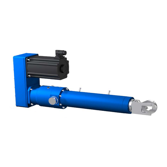
- Page 1 Electric cylinders SRSA, SVSA and SLSA Installation, operation and maintenance manual...
-
Page 3: Table Of Contents
Contents 1 Introduction – general safety instructions 1 1 Structure of safety instructions 1 2 Manual use 1 3 General safety instructions 1 4 Exclusion of liability 1 5 Future changes to user manual 2 General notes 2 1 General description of system components 2 2 Operating principle 2 3 Detailed description of supplied product 2 4 Designation... - Page 4 5 2 4 Spherical plain bearing 5 2 5 Gear 5 3 Routine checks – detailed description 5 3 1 Additional brake mounted on screw 5 3 2 Belt 6 Malfunctions 6 1 Mechanical malfunctions 6 2 Electrical malfunctions 6 3 Before requiring SKF assistance...
-
Page 5: Introduction - General Safety Instructions
This manual gives information and advice for the commissioning and hypertext links have been created to maintenance of SKF modular cylinders from the SRSA, SLSA, SVSA allow faster browsing inside the manual range of products that will minimize the risk of injury and property... -
Page 6: 3 General Safety Instructions
1.3 General safety instructions DANGER In operation, SKF cylinders could make parts move and could have hot surfaces or parts fed by electrical current, depending on the situation Serious or fatal injuries or property damage will occur if the information or precautionary measures given in this manual aren’t followed... -
Page 7: General Notes
• Motor power cable • Motor sensor cable • Motion controller • Electronic interface to make connection between PC and motion controller To know the exact definition of SKF supply, please read paragraph 2 3 Detailed description of supplied product... - Page 8 2 General notes The general drawing below illustrates the SKF electromechanical cylinder’s relationship with the user’s environment: Customer electrical cabinet Customer main controller /PLC Customer PC – « π ← motion controller 3 x 400 V AC 1 x 24 V DC...
-
Page 9: 2 Operating Principle
2 General notes 2.2 Operating principle The operating principle of SKF electromechanical cylinders is described by the cinematic drawing below (established in accordance with NF EN ISO 3952-1 standard) The operating principle of SKF electromechanical cylinders Anti-rotation system Comments Motor rotor ω... -
Page 10: 3 Detailed Description Of Supplied Product
Generally, a detailed description of the supplied product is given by the two following documents (called “documents for approval”): • Technical description • Cylinder drawing IMPORTANT: Before starting cylinder commissioning, these two documents must be read If there is a problem, please make contact with your local SKF representative... -
Page 11: 4 Designation
2 General notes 2.4 Designation Two designations: • Designation for linear unit (=actuator without motor) Example: SRSA-U-4810-0200-TRAF-N • Designation for complete actuator (=actuator with motor and servoamplifier) Example: SRSA-U-4810-0200-TRAF-L010LA21BYA1 The meaning of linear unit designation is: - U - 4... - Page 12 1 limit switch and 1 home switch 1 limit switch only 1 home switch only No switch Interface and gear ratio If required, see SKF catalogue PUB 17176 for more details Motor If required, see SKF catalogue PUB 17176 for more details Feedback Resolver...
-
Page 13: 5 Nameplate
2.6 Performances, operation limits and operation environment For more details, please read the SKF sales offer and other docu- ments for approval The cylinder’s performance and operational limits and operating environment are described in the technical requirements that define the cylinder selection... -
Page 14: 7 Storage Conditions
(see paragraph 4 2 General recommendations for use) explained on this page After three years of storage, we recommend that the cylinder is returned to SKF and a level one maintenance service be performed (see paragraph 5 1 SKF Maintenance service) 2.8 Disposal... -
Page 15: Installation - General Recommendations
3.1 Important notes DANGER Some components integrated into the SKF scope of supply are “products bought on catalogue” This means that the design and manufacturing of these components haven’t been done by SKF For all these “products bought on catalogue”, it’s the user’s responsi- bility to read the associated manufacturer’s user manual before starting... -
Page 16: 2 Mechanical Installation
3 Installation – general recommendations 3.2 Mechanical installation 3.2.1 Cylinder dimensions – Cylinder drawing To know the cylinder dimensions and the definition of its attach- ments, please look at cylinder drawing The definition of drawing cylinder is given in paragraph 2 3 Detailed description of supplied product 3.2.2 Visual cylinder position –... - Page 17 3 Installation – general recommendations Then, it’s required to measure L : equivalent dimension of L when cylinder is in any position Then, cylinder position in relation to the “zero” position given in the cylinder drawing is equal to L...
-
Page 18: 2 3 Handling - Transportation
First unplug the In case of a problem and if motor has been sold by SKF, please signal connector and then the power contact your local SKF representative Otherwise, please contact... -
Page 19: 3 2 Cables For Motor
3 Installation – general recommendations 3.3.2 Cables for motor If motor cables are included in SKF supply, please read the motor technical documentation or servoamplifier technical documentation to find the technical description and connection drawing of supplied cables Cable reference is written on the cable itself or on its... -
Page 20: And L T Definition
3 Installation – general recommendations 3.3.3.2 Mounting instructions of limit switch for “retracted position” If the limit switch for “retracted position” has been removed, please follow these instructions to mount it again correctly: Limit switch for “retracted position” Roller screw nut (back side) It’s this surface that’s detected by the limit switch In that view and in this position,... -
Page 21: 3 3 3 Mounting Instructions Of Limit Switch For "Extended Pos
3 Installation – general recommendations 3.3.3.3 Mounting instructions of limit switch for “extended position” If the limit switch for “extended position” has been removed, please follow these instructions to mount it again correctly: Limit switch for “extended position” Roller screw nut (front side) It’s this surface that’s detected by the limit switch In that view and in this position,... -
Page 22: 3 4 Home Switch
Technology: DC PNP If home switch manufacturer changes this Output: Normally opened data, SKF is not responsible for any problem arising from such changes Please check Supply voltage (V DC): with home switch manufacturer just before Consumption (mA): <10 (with 24 V DC) installing home switch Max. -
Page 23: 3 4 2 Mounting Instructions Of Home Switch
3 Installation – general recommendations 3.3.4.2 Mounting instructions of home switch If the home switch has been removed, please follow these instructions to mount it again correctly: Home switch Roller screw nut (front side) It’s this surface that’s detected by the home switch In that view and in this position, equals to + cylinder stroke... -
Page 24: 3 5 Temperature Sensor
3 Installation – general recommendations 3.3.5 Temperature sensor If this option has been taken, the following information will be required to make an electrical connection: Type of temperature sensor: Pt100 Internal wiring mode (=between plug and temperature sensor): 4 wires (→ fig. 1) Possible wiring modes with external environment: 2, 3 and 4 wires (→... -
Page 25: 3 7 Additional Brake Mounted On Screw
(specific data) for +U definition) for information only If the brake manufacturer changes this Green-blue or black data, SKF is not responsible for any problem arising from such changes Please check with the brake manufacturer just before installing the brake WARNING ... -
Page 26: 3 8 Automatic Lubrication Pump
3 Installation – general recommendations 3.3.8 Automatic lubrication pump If an automatic lubrication system is supplied by SKF, please read the manufacturer’s technical documentation in order to know how to properly install it The exact reference for the lubrication system can be found on the nameplate located on the pump body If the lubrication system manufacturer doesn’t supply paper docu-... -
Page 27: Commissioning
4 Commissioning 4 Commissioning DANGER WARNING During and after operation, some parts of the cylinder carry dangerous During operation, the cylinder surface voltages Electric shock hazard Risk of serious or fatal injuries temperature can reach high values There’s a Strictly observe the safety instructions in this manual and the safety risk of burns or fire Before any work on the instructions of manuals associated with each commissioned equipment... - Page 28 4 Commissioning 5 Switch on the power supply of the servoamplifier Check the cylinder motor brake operation (for example: when the cylinder motor torque comes on, a brake clap has to be heard Same thing when the cylinder motor torque turns off) 6 Make a small cylinder move (smaller than overstroke value which is written on cylinder drawing) in a positive direction to see the actual direction of pushing tube move (please read the end of...
-
Page 29: 2 General Recommendations For Use
• The home switch is integrated in the SKF cylinder • The home switch is fixed to the machine driven by the SKF cylinder... - Page 30 – Then, launch a search for the first zero of the encoder (or resolver) Define the zero reference once the encoder (or resolver) zero has been found Case “home switch is fixed on the machine driven by the SKF Note cylinder”...
-
Page 31: 4 How To Check Position Control Behaviour - First Approach
4 Commissioning 4.4 How to check position control behaviour WARNING – first approach At the time of first cylinder commissioning, it’s advised as a first approach to check that the position control operates correctly with- Depending on the servoamplifier manufacturer, it’s possible that out risk to generate a tracking error fault tracking error fault or overspeed fault switch off torque on the cylinder or overspeed fault (see the servoamplifier... - Page 32 4 Commissioning Detailed description of method: DANGER • Put the cylinder into the final use conditions (cylinder has to be Customer should be sure that the commis- installed inside a machine and has to be able to achieve the work sioning steps suggested in method described to the left can’t create any problems for which it has been designed) and decrease the maximum moving...
- Page 33 4 Commissioning Example: Low risk of generating over speed or tracking error faults Actual speed is the same as speed setpoint (1) Speed [mm/s] Motor current/10 and Tracking error [mm] 1 In this example, there is no difference between the speed setpoint and the actual speed If a level triggering over- speed fault is established at 230 mm/s, for example, and if this graph stays...
-
Page 34: 5 Position Control Parameters - To Be Known
4 Commissioning 4.5 Position control parameters Note – to be known A position control that is too dynamic/stiff could generate vibrations Position control parameters determine the dynamic/stiffness of (=control instability) which would make control but also its stability noise and would be damaging for the system lifetime WARNING ... -
Page 35: Maintenance, Upkeep And Routine Checks
Motor rotation can create voltage Do not touch connector pins 5.1 SKF maintenance service SKF offers a range of services for cylinder maintenance: • Level 1 maintenance for cylinder only (without motor) This service includes complete disassembly, cleaning, re-lubrica-... -
Page 36: 2 Lubrication - Detailed Description
As a general rule, the stabilized temperature of the cylinder should not exceed 80 °C (whatever surface is measured) If it’s not the case, please contact your local SKF representative in order to get technical support Note... -
Page 37: 2 1 Roller Screw (Or Ball Screw)
(temperature, speed, load, etc) While re-lubricating, the old grease goes into free space in the cylinder If all free space is filled, the cylinder would overheat Please contact your local SKF representative for advice on services that SKF offers for cylinder maintenance 5.2.2 Bearings The bearings are greased for life 5.2.3 Profile rail guides... - Page 38 5 Maintenance, upkeep & routine checks Fig. 1 Fig. 2 Fig. 3...
-
Page 39: 2 4 Spherical Plain Bearing
5 Maintenance, upkeep & routine checks Fig. 4 5.2.4 Spherical plain bearing If this option has been taken, re-lubrication data is as follows: Type: See user manual (specific data) Quantity: Until it overflows Period: See user manual (specific data) 5.2.5 Gear The gear is lubricated for life 5.3 Routine checks –... -
Page 40: Malfunctions
Cylinder is too hot Overloading Measure RMS torque value on one complete cycle (including pause time before starting a new cycle) Send this information to SKF for analysis Ambient temperature too high Comply with permitted temperature range... -
Page 41: 2 Electrical Malfunctions
If the problem hasn’t been resolved, although all the solutions given in the previous two paragraphs have been considered and implemented, get in touch with your local SKF representative for information on contacting technical support Before requiring SKF assistance, please have the following information: •... - Page 42 ® SKF is a registered trademarks of the SKF Group © SKF Group 2017 The contents of this publication are the copyright of the publisher and may not be reproduced (even extracts) unless prior written permission is granted Every care has been taken to ensure the accuracy...
Need help?
Do you have a question about the SRSA and is the answer not in the manual?
Questions and answers