Table of Contents
Advertisement
Advertisement
Table of Contents

Related Manuals for Starr Instruments FDG Series


Summary of Contents for Starr Instruments FDG Series
- Page 1 FDG series Digital Force Gauge User's Manual...
-
Page 2: Table Of Contents
Contents 1. Introduction 3.4 Printing 2. Operations 3.5 System Setting 2.1 Choose model 3.5.1 Display Mode 2.2 Choose measuring heads 3.5.2 Power Off 2.3 Power on/off 3.5.3 Backlight 2.4 Testing 3.5.4 Key Tone 2.5 Hand-held or Mounting 3.5.5 Date/Time 2.6 Storage 3.5.6 Password 2.7 Browse and Printing 3.5.7 Key Setting... - Page 3 Please Carefully Read This First ●Operators should wear protection such as a mask and gloves in case pieces or components break away from the unit under test. ●Whether the unit is ON or OFF, DO NOT exceed the capacity of the gauge. NEVER exceed 150% of the rated capacity, or the load cell will be damaged.
-
Page 4: Introduction
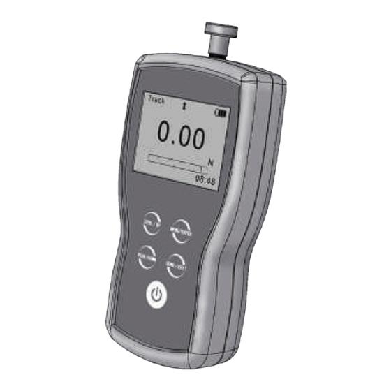
1. Introduction 1.1 Overview Fig.1-1. Measuring Shaft 1.2 LCD Screen See Fig.1-2. LCD Screen Touch Pad USB Port Multifunction Port Fig. 1-2 1. Battery icon: Battery level or charging Fig. 1-1 status,Flashes when needs to be recharged. 2.Tolerance alarm Indicator: “... - Page 5 and upper limit; “ ”: over upper limit 3. Direction Icon: “ ” tension, “ ” compression. 4. Test Mode Icon: Three measurement modes. Track, Peak and Auto Peak. 5. Current measured value 6. Analog bar: Indicates current position in whole capacity. When the bar enters the area enclosed by dotted line, means overload.
- Page 6 1.4 Specifications Accuracy ± 0.2% F.S. Selectable Units mN, N, gf, kgf, ozf, and lbf.(Selectable) Display 160*128 dot matrix LCD with LED Backlight Overload 150% of F.S. (LCD flashes beyond 110% of F.S.) Temperature Effects <0.03% FS per °C Measurement Mode Peak, Autopeak or Track Mode Set Point Tolerance Alarm...
-
Page 7: Operations
2. Operations This series force gauge is widely used in the production practice, please do the security measures before use, according to the following steps operate the force gauge. 2.1 Choose model This series force gauge has a variety of models can be selected, different models corresponding to different range and resolution, as shown in table on back cover of this manual. -
Page 8: Power On/Off
2.3 Power on/off Touch for 2 seconds to power On or Off. After switching the instrument on, you should check the model wheith it is you want. Check Battery Icon. If the power is low, should be recharged. 2.4 Testing After completion of the test preparation, testing can be done. - Page 9 2.4.3 Test Mode This series force gauge has 3 kinds of measurement test mode can choose. You can select a Measure Mode by touching under the measure interface, Or can change it in menus (See 3.2.4 Test Mode ). Track: The real time measuring mode, under this mode, press the zero key the force gauge will be cleared (remove tare).
-
Page 10: Hand-Held Or Mounting
2.5 Hand-held or Mounting The force gauge is a portable Instrument, you can do the testing hand-held, or you also can install the force gauge on the test stand so as to obtain accurate measurement results. There are 6 M4.0 mounting screw holes on the back,can be fixed on the test stand, show as Fig. -
Page 11: Menus
3. Menus Table 3-1 Unit 3.1 Structure Group Tolerance Measurement The Force Gauge has multi-level menu interface(Table 3-1). Test Mode Peak Time Alarm From the home screen, touch “ ” to enter the Menu. Storage Mode (Fig. 3-1、Fig. 3-2) Browse All Memory Browse Selected Delete Selected... -
Page 12: Measurement
3.2 Measurement The Measurement contains six selectable items: Unit, Group,Tolerance, Test mode, Peak Time and Alarm. (Fig, 3-3) Fig. 3-3 3.2.1 Unit The measuring unit can be selected under this menu. Different range models may have different unit selection capabilities. See Fig.3-4. Fig. -
Page 13: Tolerance
3.2.3 Tolerance Figure 2-6 In the Tolerance menu, program upper and lower limit for GO/NG Measurement. The upper limit value must be greater than the lower Fig. 3-6 limit, and both limit value can not be greater than 110% of the rated capacity. See Fig.3-6. 3.2.4 Test Mode Fig. -
Page 14: Alarm
The range is 1~99 seconds. (Fig. 3-8) 3.2.6 Alarm You can turn on/off the sound of tolerance Fig. 3-9 alarm( Fig.3-9). The sound for overload alarm cannot be turned off. 3.3 Memory Fig. 3-10 In this menu, you can set the memory mode, browse the data in memory or delete it/them. -
Page 15: Browse Data
Series: Continuous storage mode, only in Auto Peak mode is effective. When a peak capture time interval is reached, the peak value is saved, no need touch any key (Fig. 3-11). 3.3.2 Browse Data Fig. 3-12 You can browse the data in memory with two method, Browse All or Browse Selected. -
Page 16: Printing
Delete selected: Delete data in number range selected. Delete All: Delete all data saved. Before delete data, a warning window will pop up for further confirmation. 3.4 Printing Fig. 3-15 The force gauge can be connected to a printer for printing the report. - Page 17 Print Recent: Print some data measured recently(Fig. 3-17) Print Selected: Print data in a number range(Fig. 3-18). Fig. 3-17 Fig. 3-18 Print All: Print all data in memory(Fig. 3-19). It may take a long time to print all the data and need many printing paper, so a prompt window will pop out to ask for confirmation.
-
Page 18: System Setting
3.5 System Setting 3.5.1 Display Mode LCD display direction can be transformed according to the position of force gauge Fig. 3-21 automatically. You can set it to Obverse or Reverse and not Fig. 3-22 Automatic. 3.5.2 Power Off The force gauge can turn the power off automatically, some time interval after no Fig. -
Page 19: Backlight
3.5.3 Backlight The force gauge can turn off backlight, some time interval after no measuring and no any operation. You can select this time or turn it on or off always.(Fig. Fig. 3-24 3-24) 3.5.4 Key Tone (Fig. 3-25) Fig. 3-25 3.5.5 Date/Time (Fig. -
Page 20: Key Setting
The default System password is“123”. You can change it to your favorite. You should enter the old password first, then enter a new one. Fig. 3-27 Fig. 3-28 3.5.7 Key Setting The key is a multifunction key, It can be set as "store the current display value(Storage)"... -
Page 21: Language
restore, the gauge can be restored to factory settings. it will lose that some imformation set by customs.Carefully use this function! Restoring to Default Setting, the password must be enter and a prompt must be confirmed. 3.6 Language Here you can select the language appropriate. 3.7 Information Fig. -
Page 22: External Interface
4 External Interface The force gauge have 2 external ports, a USB port and an MD8 port. USB port MD8 port 4.1 USB Port The USB port is used to transmit data to Fig. 4-1 PC and recharge. Connect the USB cable to a charger for recharging. Connect to the PC for upload data. - Page 23 Table 4-1 The pins assignment of multifunction port is shown in Table 4-1. MD8 multifunction port The specification of RS232 is shown in Table 4-2 Description Table 4-2 RS232- Transmit(TX) RS232- Receive (RX) RS232 Specifications RS232- Ground Data word length 8 bits Alarm Output A+ Stop bit...
- Page 24 Alarm output: There are two alarm outputs, you can connect them to the other equipment (such as test stand, PLC etc.), or connect to some alarm units. Fig. 4-2 Fig. 4-3 Maximum permissible voltage pin 7 to pin 6, pin 4 to pin 6: 35V; pin 6 to pin 7, pin 6 to pin 4:...
-
Page 25: Maintain And Calibration
5 Maintain and Calibration 5.1 Charging When the battery are low, the icon “ ” will be displayed. The batteries should be charged immediately. Connect the gauge and the charger use the USB Fig. 5-1 cable, and then connect the charger with AC socket to start charging. -
Page 26: Calibration
5.2 Calibration Because of the sensor material performance or the influence of external factors, there may be errors in a certain range after a period of time use. Should send the force gauge to a specialized testing organization for calibration. ❶... - Page 27 ⑥ Touch to enter the next calibration. Touch can interrupt the calibration. When the 5 times calibration had been finished or be interrupted, a confirm window will pop up to ask for save or not save the calibration. (Fig. 5-3) Touch to select, then press If "YES"...
-
Page 28: Appendix A-1 Packing List
Appendix A-1 Packing List... -
Page 29: Dimensions
A-2 Dimensions... -
Page 30: Warranty Card
Warranty Card Description: Digital Force Gauge Model: User: Tel: Add: Agent: Tel: Date: Warranty Description Please use our product exactly according to our user's manual. All products sold by our company or authorized dealer are covered by 12 month warranty. Anthropogenic causes, irresistible natural factors cause the product damage, our company will not warranty. - Page 31 Capacity/ Resolusion Model FGD-5 5/0.0005 1.1/0.0001 18/0.005 500/0.05 5000/0.5 FGD-10 10/0.001 1/0.0001 2.2/0.0005 35/0.01 1000/0.1 10000/1 FGD-20 20/0.005 2/0.0005 4.4/0.001 70/0.01 2000/0.5 20000/5 FGD-50 50/0.005 5/0.0005 11/0.001 180/0.05 5000/0.5 50000/5 FGD-100 100/0.01 10/0.001 22/0.005 350/0.1 10000/1 FGD-200 200/0.05 20/0.005 44/0.01 700/0.1 20000/5 EFG500...
Need help?
Do you have a question about the FDG Series and is the answer not in the manual?
Questions and answers