Table of Contents
Advertisement
Advertisement
Table of Contents

Related Manuals for Starr Instruments TGD-100


Summary of Contents for Starr Instruments TGD-100
- Page 1 TGD-100 Ultrasonic Thickness Gauge Instruction Manual VER:3.1...
-
Page 2: Table Of Contents
Contents 1 INTRODUCTION ..................3 1.1 S ................3 COPE OF APPLICATIONS 1.2 P ................... 3 RIMARY HEORY 1.3 M ................3 EASURING RINCIPLE 1.4 A ..................4 PPEARANCE 1.5 K .................... 4 EYBOARD 1.6 D ................... 4 ISPLAY SYMBOLS 2 PRODUCT SPECIFICATIONS .............. - Page 3 5.6 U ................16 PARALLEL SURFACE 5.7 I ’ ..........16 NFLUENCE OF MATERIAL S TEMPERATURE 5.8 M ............16 ATERIAL WITH LARGE ATTENUATION 5.9 R ................17 EFERENCE TEST PIECE 5.10 S ............. 18 EVERAL MEASURING METHODS 5.12 C ................
-
Page 4: Introduction
1 Introduction 1.1 Scope of applications Ultrasonic Thickness Gauge measuring with ultrasonic wave is applicable for measuring the thickness of any material in which ultrasonic wave can be transmitted and reflected back from the other face. The gauge can provide quick and accurate measurement to various work pieces such as sheets of board and processing parts. -
Page 5: Appearance
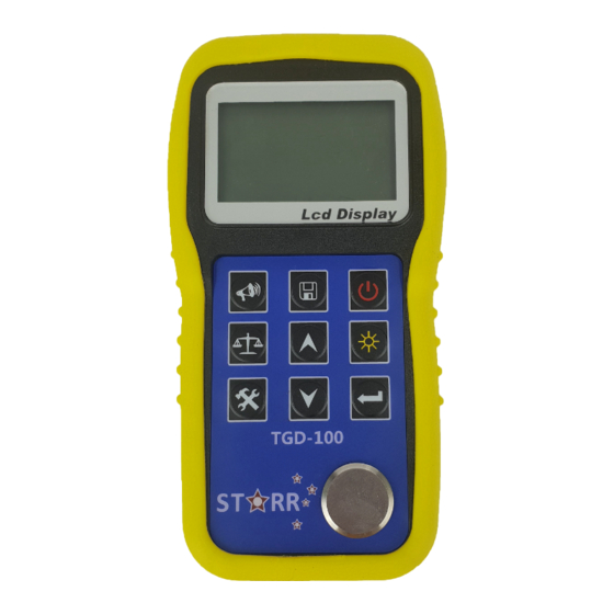
1.4 Appearance THICKNESS GUAGE Ultrasonic 1.5 Keyboard ☼ Power ON/OFF LCD backlight on/off Sound velocity Save data / Browse data Calibration standard block of 4.00mm Function selector Adjusting sound velocity and thickness; key for moving menu cursor ... -
Page 6: Product Specifications
2 Product Specifications 2.1 Technology parameter Display: 128×64 LCD with LED backlight. Measuring range: 0.75mm~300.0mm (0.03inch~11.8 inch) Sound Velocity Range: 1000m/s~9999m/s (0.039~0.394in/µs Display resolution: 0.01mm or 0.1mm (lower than 100.0mm) 0.1mm (more than 99.99mm) Accuracy: ±(0.5%Thickness +0.02)mm, depends on Materials and conditions ... -
Page 7: Operation
3 Operation 3.1 Preparation for measurement 3.1.1 Insert the probe plug into the socket for the probe on the main unit, 3.1.2 Press to turn on the instrument. 3.1.3 LCD will Display software editions information about the instrument. And then display Latest sound velocity. 3.2 Adjusting sound velocity pressing , If the current display is thickness, by... -
Page 8: Setting Probe Frequency
3.3 Setting probe frequency key Press to move the cursor to the position as that shown in the following figure. Press to change the frequency setting. LCD will display in sequence the probe frequency to be set 5M, 7M or ZW. -
Page 9: Measurement Of Thickness
3.4 Measurement of thickness First, set the sound velocity and then coat the coupling agent at the place to be measured, couple the probe with the material to be measured, now you can begin the measurement. The screen will display the thickness of material to be measured. -
Page 10: Measurement Of Sound Velocity
Note: After every change of the probe, probe temperature, ambient temperature changes, etc. After the work environment, or working for some time after the discovery measurement errors should see the standard test block measured value is accurate, if the difference would be larger school Zero operation. -
Page 11: Setting Alarm Thickness Limits
3.7 Setting alarm thickness limits The instrument will alarm if the measurement is out of limits. When the measurement is lower than the low limit or higher than the high limit, the buzzer will alarm. The alarming limit is set as follows: 1) Press , move cursor to ALARM. - Page 12 Measurement units: metric and Imperial Receiving gain: LOW and HIGH 1. The LOW is mainly used for measuring coarse material with high scatter and small sound absorption, such as cast aluminum, cast copper and other metallic parts. 3) Display resolution: 0.1mm(LOW) and 0.01mm(HIGH) Minimum capture measurement OFF and ON...
-
Page 13: Print Function
6. Press under thickness-measuring state to enter into 2-Point CAL, the screen will prompt to calibrate the thinner piece. 7. Measure the thinner standard test piece, use or to adjust the measurement to standard value. Press ENTER, the screen prompts to measure the thicker piece. - Page 14 send measured results through menu selection.
-
Page 15: Memory Manage
3.8.3 Memory Manage Erase file: Clearing selected files Erase all data: Clearing entire memory Erase CAL data: Clearing calibrating data 4 Data logger operation 4.1 Logging readings into memory The instrument divides the memory unit into 5 files. Each can save 100 measurement values. -
Page 16: Reviewing Stored Thickness Readings
4.2 Reviewing stored thickness readings 1) Use to move cursor to the position shown in the following figure: 2) Pressing to brown the contents of memory. Press , erase current data. or review stored thickness. 3) Pressing 4.3 Clearing current thickness Value Under the state of Reviewing stored readings, press ... -
Page 17: Measuring Cylindrical Surface
5.4 Measuring cylindrical surface When measuring cylindrical material, such as pipes, oil tubes, etc., it is very important to select properly the included angle between the probe’s crosstalk interlayer plate and the axial line of the material to be measured. Briefly to say, first couple the probe with the material to be measured, make the probe’s crosstalk interlayer plate be perpendicular or parallel to the axial line of the object, shake the probe vertically along the axial line... -
Page 18: Reference Test Piece
will cause abnormal readouts even no display (generally, the abnormal readout is less than actual thickness). In this situation, this kind of material doesn't apply to be measured with this instrument. 5.9 Reference test piece When making accurate measuring for different materials under different conditions, the more the standard test piece is near to the material to be measured, the more accurate the measurement is. -
Page 19: Several Measuring Methods
first, and then measure the work piece with the measured speed. 5.10 Several measuring methods a) Single measuring way: measurement at one point. b) Double measuring way: measure with probe at one point twice. During the two measurements, the probe’s crosstalk interlayer plate should be placed in perpendicular direction, and take the min. -
Page 20: Changing Probe
5.11 Selecting probes Frequenc Min. area Probe Measuring range Application General 5P 10 Straight probe 1.0mm~300.0mm 20×3mm 5MHz (steel) 5P10/90 General bent probe 0.75mm~25.0mm 15×2mm 7P6 300 7 MHz thin work piece (steel) 0.75mm~25.0mm 5 MHz 30mm high temperature ZW5P10 (steel) 3.0mm~300.0mm... -
Page 21: Preventing Errors In Measurement
value. For attenuation under different frequencies, it will increase as the frequency. Secondly, due to coarse crystal particle and if coarse out-phase structure exists, it will cause abnormal reflection, i.e. the grass-shaped echo or tree-shaped echo, so that the measuring will have error reading, and cause wrong judgment. -
Page 22: Rust, Corrosion And Pit
the actual thickness. Another error result is called “pulse envelop, cyclic leap”, its result is that the measured value is larger than the actual thickness. To prevent these kinds of errors, please repeat the measurement to check the results. 6.2 Rust, Corrosion and Pit The rust and pit on the other surface of the object will cause irregular change in readouts. -
Page 23: Abnormal Readout Of Thickness
transmitting speed in these two materials, which will cause error. In addition, different thickness in oxidation layer will cause different error. Please be careful in this. One can make a reference piece from a batch of objects by measuring with micron micrometer or caliper, and use it to calibrate the instrument. -
Page 24: Cleaning The Instrument ' S Case
to prevent rust. When one wants to use them again, first clean them, then he can have normal operation. 7.2 Cleaning the Instrument’s Case Alcohol will corrode the case, especially the LCD of the instrument. Therefore, when you clean the instrument, you can do that just with some clean water and clean it slightly. - Page 25 The component of the instrument is damaged and it is impossible to measure. The LCD is abnormal. c.During normal operation, the error is too large. The keyboard doesn't function or is in disorder. Since Thickness Gauge is a high-tech product, its maintenance should be conducted by professional trained person.
-
Page 26: Operation To Restore The Factory Parameters
9. Operation to restore the factory parameters Actual use, if the measured value of the error or deviation is too large, may be operator error or other causes within the parameters of the machine error, the best approach is to restore the factory parameters, as follows: Press , move cursor to MENU then Press ... -
Page 27: Configuration
10.Configuration ITEM QUANTITY NOTE Main Unit Transducer Couplant Standard Instrument case configuration Operating Manual 1.5V battery Transducer:N02 Transducer:N07 Transducer:HT5 Mini Thermal printer Optional Print cable Configuration “DataPro” Software Communication cable... - Page 28 Sound velocity for Different Materials Sound velocity Material (m/s) (inch/µs) Aluminum 6320-6400 0.250 Zinc 4170 0.164 Silver 3607 0.142 Gold 3251 0.128 2960 0.117 Steel, common 5920 0.233 Steel, stainless 5740 0.226 Brass 4399 0.173 Copper 4720 0.186 Iron 5930 0.233 Case Iron 4400-5820...
- Page 29 Certificate of approval Products Name::_Ultrasonic Thickness Gauge _ Products Type: Main unit No:___________________________ The product accords with the technical criteria and is allowed to sell. QUALITY CONTROL ENGINEER:_________________ Inspection date:_____________...
Need help?
Do you have a question about the TGD-100 and is the answer not in the manual?
Questions and answers