Table of Contents

Related Manuals for ThinkRF R5750


Summary of Contents for ThinkRF R5750
- Page 1 ThinkRF R5750 Real-Time Spectrum Analyzer with GNSS User Guide Version 1.0 March 2019 Document no. 75-0040-190401 Copyright © 2019 ThinkRF Corporation, All rights reserved. All product names are trademarks of their respective companies.
- Page 2 Customer. ThinkRF will warrant repaired units for a period of 90 days from date of or otherwise, for any shipment from ThinkRF to the Customer. If the remaining period on the original...
-
Page 3: Table Of Contents
Document Feedback ...................... 6 Obtaining Technical Assistance ..................6 Overview of the ThinkRF R5750 ................... 7 Getting Familiar with the ThinkRF R5750 ............... 8 Installing the ThinkRF R5750 ..................11 Preventing Electrostatic Discharge Damage ..............11 Unpacking the Box ......................12 Connecting the Antennae, Ethernet and Power Cables ..........12... - Page 4 Resetting the ThinkRF R5750 to Factory Settings ........... 33 Status Indicator LEDs ....................34 Power (PWR) Indicator LED ..................34 Status (STS) Indicator LED ...................34 Reference (REF) Clock Source LED ................35 LOCK Indicator LED ......................35 LINK Status LED ......................36 ACT Indicator LED ......................36 Hardware Reference ....................
-
Page 5: Preface
Obtaining the Latest Documentation and Software Please visit the ThinkRF website at https://www.thinkrf.com/documentation/ to obtain the latest R57500 documentation. Latest software and firmware releases are also available on the ThinkRF website at https://www.thinkrf.com/download-updates/. ThinkRF R5750 Real-Time Signal Analyzer User Guide... -
Page 6: Document Feedback
9 AM to 5 PM Eastern Time, Monday to Friday. Contact us at support@thinkrf.com or by calling +1.613.369.5104. Before contacting support, please have the following information available: • R5750 serial number (located on the identification label on the R5750 device’s underside) • The product version •... -
Page 7: Overview Of The Thinkrf R5750
The R5750 is ideal for monitoring, management and surveillance of transmitters, whether they are in-building or spread across a geographic area. Applications include but are not limited to spectrum analysis, 5G wireless technology, research, test and measurement, spectrum monitoring and OEM integration. -
Page 8: Getting Familiar With The Thinkrf R5750
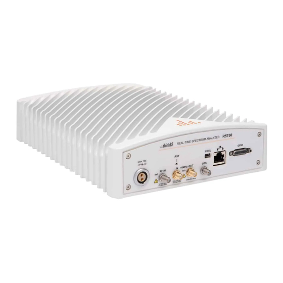
The R5750 Real-Time Spectrum Analyzer provides Gigabit Ethernet for stand-alone, remote and distributed applications. ThinkRF supports a rich set of industry-leading standard protocols and APIs, enabling the R5750 to easily integrate into your new or existing applications. Standard protocols include the Standard Commands for Programmable Instruments (SCPI) protocol for controlling and obtaining status from the R5750 and the VITA 49 Radio Transport (VRT) protocol for digitized data and its associated context information. - Page 9 Overview of the ThinkRF R5750 Front Panel The front panel of the R5750 contains the power switch, status indicator LEDs, and the input connector for the RF antenna port. Rear Panel The rear panel of the R5750 contains the power input, 10 MHz reference clock I/O, hardware reset button, input connector for the GNSS antenna, USB console (CNSL) port, Ethernet port, and GPIO port.
- Page 10 Overview of the ThinkRF R5750 ThinkRF R5750 Real Time Signal Analyzer User Guide...
-
Page 11: Installing The Thinkrf R5750
Electrostatic discharge is more likely to occur with the combination of synthetic fibers and dry atmosphere. Always follow these steps to prevent ESD. Warning: Never open the front or rear panels of the R5750 as personal injury may result and opening the chassis will void the warranty. There are no user-serviceable parts inside. -
Page 12: Unpacking The Box
Installing the ThinkRF R5750 Unpacking the Box This section lists the items that come with your R5750 analyzer. If any of the items are missing or damaged, please contact your ThinkRF customer service representative. The R5750 shipping box contains the following: •... -
Page 13: Choosing The Mount Location For The R5750
R5750 analyzer. Caution: To prevent damage to the R5750 radio receiver, do not install or operate the R5750 within 2 feet (60 cm) of devices that transmit more than +15 dBm power, such as Wi-Fi access points. -
Page 14: Connecting To The Thinkrf R5750
R5750 using SCPI commands, and transmission of data using the VRT protocol. Determining Your Network Topology and IP Address Allocation To connect with the R5750 analyzer, you must decide the topology of your network connection and how your R5750 obtains its IP address. -
Page 15: Connecting Directly To The R5750
Ethernet card or USB adapter to connect to the R5750. Note: The Ethernet interfaces on both the PC and the R5750 must be configured for the same IP address allocation method before you can make a direct connection. - Page 16 Note: While the R5750 is searching for a DHCP server, the STS LED blinks yellow slowly until it obtains an IP address either via DHCP or Auto-IP. The STS LED blinks in a green heartbeat pattern if it has set up successfully to using an Auto-IP address.
-
Page 17: Connecting To The R5750 Across A Network
Before you connect to the R5750, you must decide on your IP address allocation method. The PC and R5750 do not need to use the same IP address allocation method, but if you are using the ThinkRF Discovery tool to locate the R5750 analyzer, they must be on the same subnet. - Page 18 IP address or use the USB console. If necessary, consult your network administrator. Once you have the R5750 IP address, you can use it to communicate with the device. ThinkRF R5750 Real Time Signal Analyzer User Guide...
-
Page 19: Using The Thinkrf R5750 Administration Console
All of these functions may be performed over the network either locally or remotely. You can connect to the R5750 Administration Console by entering the IP address of your R5750 into a web browser. The IP address is shown in the S240 software as the connected device. -
Page 20: Configuring R5750 Time Synchronization
Note: The R5750 analyzer stores its time based on the Coordinated Universal Time (UTC) and otherwise has no notion of local time-zones. Conversely, the web dialog translates and displays the R5750 time based on the local time-zone setting of the PC. To configure the R5750 time synchronization method: 1. -
Page 21: Configuring The R5750 Ip Address
IP address manually (using a static address). Caution: If the R5750 IP address is set to a static IP, the only way to communicate with the R5750 is via that IP address. If you mistakenly enter the wrong IP address and/or subnet mask, or forget the IP address, you can change the IP configuration using the USB console or by resetting the R5750. -
Page 22: Updating The R5750 Firmware
The firmware installation file contains firmware images associated with the R5750 FPGA, Linux operating system and the embedded application. The update process copies the new images to the R5750, but does not remove the currently installed images. The new firmware installation will only take effect after the R5750 is restarted. -
Page 23: Customizing R5750 Calibration Settings
You can click OK to proceed, or Cancel to defer the device restart. Note: If the R5750 is not restarted immediately after a firmware install process, then the newly installed firmware will take effect upon the next restart of the R5750 regardless of whether it is a software restart or a power-on reset. - Page 24 When the upload is complete, the custom calibration file appears on the list of calibration files. The most recently uploaded file is listed at the top of the table. 4. Restart the R5750 (you can click Restart in the left pane, or toggle the power switch).
- Page 25 DELETE in the Actions column. 3. Repeat step 2 for all custom calibration files listed in the table. 4. Restart the R5750 (you can click Restart in the left pane, or toggle the power switch).
-
Page 26: Restarting The R5750
Using the ThinkRF R5750 Administration Console Restarting the R5750 You can restart the R5750 via the Administration Console. Performing a device reset from the Administration Console is equivalent to a power-on reset. To restart the R5750: 1. Click on the Restart link in the left pane of the Administration Console. -
Page 27: Using The Thinkrf R5750 Usb Console
1. Power on the R5750 and wait approximately 30 seconds for boot-up. 2. Connect The USB cable to the R5750 USB console port and your PC’s USB port. Your PC should automatically detect the R5750 as a new USB device and install the appropriate driver. - Page 28 7. Refer to the R5750 Programmer's Guide associated with the firmware release of your R5750 for the SCPI commands to use with your R5750 via the USB console terminal window. The firmware release version of the R5750 is returned with the *IDN? SCPI command.
-
Page 29: Configuring The R5750 Ip Address
The R5750 supports dynamic IP address allocation using DHCP, or manual IP address configuration (via static IP address). Caution: If the R5750 IP address is set to a static IP, the only way to communicate with the R5750 is via that IP address. If you mistakenly enter the wrong IP address and/or subnet mask, or forget the IP address, you can change the IP configuration using the USB console or by restarting the R5750. -
Page 30: Using The Gnss Module
R5750 analyzer, the GNSS module also provides a third 10MHz reference clock source option for synchronized time-stamps on VRT packets. You can configure the R5750 to use the GNSS reference clock, via the USB console, or via Telnet or HiSLIP connections. The USB console is used in the following examples. -
Page 31: Getting Real-Time Geolocation Data
If no GNSS fix is available, the system response is “INT”. Getting Real-Time Geolocation Data You can obtain real-time GNSS position data from the R5750 GNSS module. During data capture, the real time GNSS location context packets are sent periodically in the VRT data stream. - Page 32 When 0 is returned, the GNSS data is current. When 512 (or bit 9) is returned, the GNSS is out of lock. See “Appendix D: Questionable Status Register (QSR) in the ThinkRF R5750 Programmer’s Guide for more information.
-
Page 33: Resetting The Thinkrf R5750 To Factory Settings
Resetting the ThinkRF R5750 to Factory Settings If for any reason you cannot connect to the R5750 via the Ethernet port, you can restore device factory settings to reset IP configuration, and obtain an IP address dynamically using DHCP. Performing a factory resent also sets the reference level calibration back to factory default values. -
Page 34: Status Indicator Leds
Status Indicator LEDs The front panel of the R5750 analyzer includes status indicator LEDs as shown in the following figure and described in the following sections. Power (PWR) Indicator LED The PWR indicator LED indicates that the input and internal power voltages are correct. -
Page 35: Reference (Ref) Clock Source Led
Ready for connection Reference (REF) Clock Source LED The REF LED indicates whether the R5750 is using the internally generated 10 MHz reference clock or an external reference clock provided via the 10 MHz IN SMA connector, and whether that selected reference clock source is of sufficient quality for the internal PLL to lock to it. -
Page 36: Link Status Led
GigE Ethernet link connection ACT Indicator LED The ACT indicator LED indicates whether there is any activity on the Ethernet connection. ACT Indicator LED Ethernet Activity No Ethernet activity Green Ethernet transmit or receive activity ThinkRF R5750 Real Time Signal Analyzer User Guide... -
Page 37: Hardware Reference
Hardware Reference This section provides physical and performance specifications, and port and cable pinouts for the R5750. System Specifications The following table outlines the physical and electrical specifications for the R5750. Description Design Specification Dimensions 257.3 x 193.7 x 60/66 mm (10.13 x 7.63 x 2.36/2.61... -
Page 38: Ethernet Rj-45 Port Pinout
(see the R5750 Programmer's Guide), it is best to inject signals lower than 10 dBm. Additionally, any external signal sources connected to RF IN must be turned on only after powering on the R5750 and turned off prior to powering down the R5750. -
Page 39: Gpio Port Pinout
Second) input, external triggering input/output and specific radio front end control and status. Caution: Improper use of the GPIO may cause irreparable damage to the R5750. Do not use the GPIO without prior consultation with ThinkRF's service organization. The following pinouts are specific to the R5750 models only. -
Page 40: Usb Console Port Pinout
Hardware Reference USB Console Port Pinout Signal +5 VDC Data - Data + Ground RJ-45 Straight-Through Ethernet Cable RJ-45 Crossover Ethernet Cable ThinkRF R5750 Real Time Signal Analyzer User Guide... -
Page 41: Operational Considerations And Maintenance
Hardware Reference Operational Considerations and Maintenance The R5750 should be operated only within its specified operation temperature and specification of 0°C to 50°C. The ideal operating temperature for optimum performance is between 20°C to 25°C. Caution: Do not expose the device to direct sunlight or radiation from other sources of heat.
Need help?
Do you have a question about the R5750 and is the answer not in the manual?
Questions and answers