
Related Manuals for Girard Products VISION

Summary of Contents for Girard Products VISION
- Page 1 VISION PATIO AWNING INSTALLATION SERVICE and REPAIR Rev. 03052019JM RV AWNING PRODUCTS 1361 CALLE AVANZADO, SAN CLEMENTE, CA 92673 (800) 382-8442 FAX (949)276-5500 www.girardrv.com...
- Page 2 WARNING “To reduce the risk of electric shock the operator power is to be provided from a weatherproof junction box in the case of permanent wiring, as per 314.15 of the National Electrical Code, NFPA 70.” To prevent the motor protector from tripping do not exceed 2 minutes of operation per hour.
- Page 3 Girard Systems awnings may be operated in light wind and rain conditions. When periods of heavy rain and or high wind are expected the awning must be closed. Never leave the Awning open and unattended. Damage caused by wind and rain is not covered by warranty. All awnings must be closed prior to moving the vehicle for any reason.
-
Page 4: Table Of Contents
CONTENTS Basic System Overview ……………………………………………………………………………………………. 5 Installation Instructions …………………………………………………………………………………………… 6 Product Description …………………………………………………………………………………………………. 7 Tools Required ……………………………………………………………………………………………………….. 7 A. Unpacking ……………………………………………………………………………………………………….. 8 B. Layout and Mounting the Brackets …………………………………………………………………….. 9 Awning Bracket placement chart …………………………………………………………………………….. 10 C. Mounting the Awning ……………………………………………………………………………………… 11 D. -
Page 5: Basic System Overview
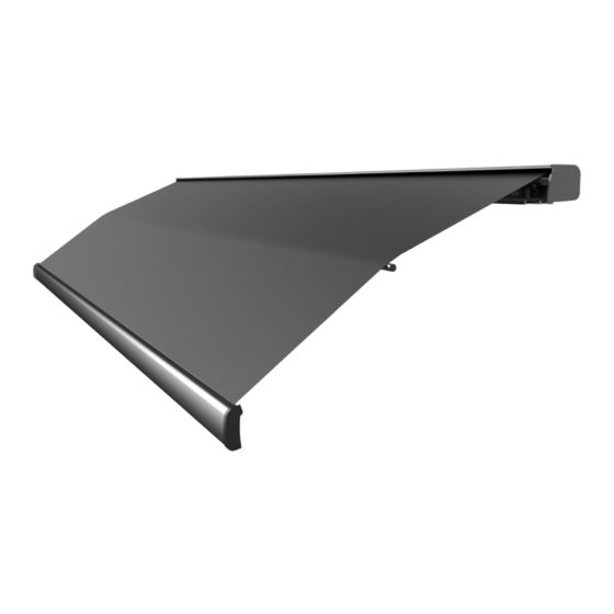
BASIC SYSTEM OVERVIEW The VISION Awning consists of three main components: 1. Mechanical system – consisting of: • The enclosure (or cassette) protects the awning while closed. • The roller tube which is mounted within the cassette. • The top cover or fabric rolled onto the roller tube and connected to the lead rail that extends from the enclosure when the awning is opened. -
Page 6: Installation Instructions
INSTALLATION INSTRUCTIONS FOR PERSONAL SAFETY AND QUALITY OF INSTALLATION, A MINIMUM OF TWO INSTALLERS IS RECOMMENDED FOR THIS PRODUCT. Before beginning to install the awning please verify the following; • The vehicle is parked and leveled on suitable hard standing. •... -
Page 7: Product Description
PRODUCT DESCRIPTION The VISION is a dual pitch awning system provides protection from the sun at a touch of a button. The VISION awning is built to your specifications with the highest quality materials available, your unit features: • A standard motor that operates with a wireless motor controller or a wireless motor that operates with an integrated motor control. -
Page 8: Unpacking
A. UNPACKING Before starting any of the installation procedures: 1. Unpack the awning and inspect the product for any possible damage that may have occurred during shipping. 2. Ensure that the length and motor placement of your awning are correct. 3. -
Page 9: Layout And Mounting The Brackets
B. LAYOUT AND MOUNTING THE BRACKETS 1. MOUNTING THE AWNING – NOTE: The clearances needed for mounting the VISION varies by manufacturer. The shape of the roof, the depth of installation and all other factors should be taken into consideration when installing this product. -
Page 10: Awning Bracket Placement Chart
Page 10 of 32... -
Page 11: Mounting The Awning
C. MOUNTING THE AWNING 1. Lift the awning into position for fastening to the mounting brackets. a. Ladders are usually sufficient however a scaffold or forklift may be used. b. If using a forklift use all necessary caution to protect the surface of the awning. -
Page 12: Motion Sensor
D. MOTION SENSOR NOTE: The Motion Sensor requires a hard wired 12V. D.C. connection. 12v DC MOTION SENSOR (Hard wired) The Motion Sensor will come from the factory pre-programmed. A hole may need to be drilled for the power cable. 1. -
Page 13: Testing And Adjustments
TESTING AND ADJUSTMENTS OVERVIEW A. Adjusting Motor-limit switches B. Adjusting Pitch C. Testing the Anemometer D. Adjusting Lead Rail A. ADJUSTING MOTOR LIMIT SWITCHES TOOLS REQUIRED Black plastic key provided with awning or 4mm (5/32”) Allen wrench. NOTE: The motor limit switches have been adjusted to the correct positions at the factory prior to shipment. - Page 14 4. Extend the awning a few feet to gain access to the motor. Locate the motor (standard installation is on the right hand side of the awning). The limit adjustment pots are located on the head of the motor. Using the symbols printed next to the adjustment screws, turn the black key (or 4mm Allen wrench) to make the necessary adjustments.
-
Page 15: Adjusting Pitch
B. ADJUSTING PITCH NOTE; Adjustment of the Elbow height and pitch, will affect the height of the awning lead rail when it is fully deployed. Ensure that when making any of these adjustments the final height of the lead rail is no less than 7’ (84”). This adjustment is usually required after an arm replacement. -
Page 16: Testing The Motion Sensor
TESTING THE MOTION SENSOR 1. Partially extend the awning. 2. Physically activate the Motion sensor by pulling down the corner of the lead rail about 12” and then release. This should create enough movement to activate the motion sensor. 3. At this point the awning should retract; if not, check the electrical connections to the selected power source. -
Page 17: Troubleshooting Guide
TROUBLESHOOTING GUIDE PROBLEM: The lead rail is binding on the side of the awning casing; i.e. the rail is offset from housing. SOLUTION: • Open the awning about 3 feet. • Loosen the lead rail adjustment screws on all arms. •... - Page 18 • Check that the motor’s thermal protection circuit breaker has not tripped. The 110V AC motor supplied in your VISION Awning is designed for intermittent use and may cut out temporarily if it has overheated. When this occurs you must...
- Page 19 There is no apparent binding of the awning components. SOLUTION: The VISION Awning is equipped with a manual override motor which has manual limit settings. The IN limit may need to be adjusted to allow the box to be closed tighter.
-
Page 20: Common Repair Procedures
COMMON REPAIR PROCEDURES MOTOR REPLACEMENT NOTE: Replacement procedures vary due to motor styles, placement, factory installation methods, and preferences of different vehicle manufacturers. These variations primarily effect how the motors are accessed; replacement operations are generally the same for any situation. A. - Page 21 4. Remove both of the motor bolts that fasten the motor to the spider bracket. Mark the slots from which the bolts were removed and then remove the spider bracket. 5. Loosen the small bolt that secures the roller tube support to the main housing. DO NOT OVER-LOOSEN OR ATTEMPT TO REMOVE THIS BOLT.
- Page 22 B. INSTALLING THE NEW MOTOR 1. With the new motor in hand, align the notch in the black drive-disk (at the far end of the motor) with the indentation in the awning roller tube. Slide the motor all the way in. Turn the motor until its notch also lines up with the roller tube indentation.
-
Page 23: Fabric Replacement
(Figure 13) FABRIC REPLACEMENT IMPORTANT NOTE: THESE PROCEDURES REQUIRE THE USE OF A MANUAL CRANK. IF NO MANUAL CRANK IS AVAILABLE THE MOTOR LIMIT SWITCHES MUST BE USED TO CREATE THE SETTINGS. PLEASE REFER TO THE “ADJUSTING MOTOR LIMIT SWITCHES”. USE THE MOTOR SPARINGLY TO PREVENT OVERHEATING. - Page 24 LEAD RAIL END CAP HOUSING END PLATE LOCK PLATE (Figure 14) (Figure 15) 4. Carefully slide out the entire fabric from the left end of the roller tube and lead rail. Make sure the poly rope clears the support bracket. NOTE: FOR PERSONAL SAFETY, AND BEST RESULTS IT IS RECOMMENDED THAT TWO TECHNICIANS PERFORM THIS TASK.
-
Page 25: Fabric Replacement
3. Center the fabric on the roller tube and then smooth all of the wrinkles out at the lead rail. Insert a self-tapping screw into the roller tube on the side opposite the motor location. The fabric will center itself on the lead rail. (Figure 10). 4. -
Page 26: Arm Replacement
ARM REPLACEMENT Follow this procedure when a damaged, spring loaded arm needs to be replaced. There are no repairable parts inside of the arm; if the elbow joint has broken the entire arm must be replaced. TOOLS REQUIRED: • 19mm (3/4”) open-end wrench •... - Page 27 4. At the shoulder assembly of the arm, in the cassette, remove both 19mm lock nuts and washers, or the bolt and nut. 5. Remove the forward most bolt from the arm and shoulder connection. Use this bolt for the new arm installation if new hardware is not provided. Hold the bottom pitch adjustment block with your thumb to keep it from falling.
-
Page 28: Exploded Diagram
Page 28 of 32... -
Page 29: Physical Dimensions
Page 29 of 32... -
Page 30: Component Identification
COMPONENT IDENTIFICATION ITEM DESCRIPTION PART NUMBER Rollertube Center Support Bkt Assy BLK 7100001-01B Main Housing Arm Support Guide 7100002-02 Cover Housing 16' BLK 7100016-03B Cover Housing 18' BLK 7100018-03B Cover Housing 19'8" BLK 7100020-03B Cover Housing 22' BLK 7100022-03B Rubber Gasket 16' 7100016-04 Rubber Gasket 18' 7100018-04... - Page 31 Fabric Guide 22' Plastic 7100022-09 Fabric Guide Support 16' BLK 7100016-10B Fabric Guide Support 18' BLK 7100018-10B Fabric Guide Support 19'8" BLK 7100020-10B Fabric Guide Support 22' BLK 7100022-10B Cover Plate Assy LH BLK 710L004-11B Lock Plate Assy LH BLK 710L005-12B Rollertube Support Bkt Assy BLK 7100006-13B...
- Page 32 Crossbar 19'8" BLK 7100020-34B Crossbar 22' BLK 7100022-34B Crossbar String for 16' (32' strip) 7100016-36 Crossbar String for 18' (36' strip) 7100018-36 Crossbar String for 19'8" (40' strip) 7100020-36 Crossbar String for 22' (44' strip) 7100022-36 Arm Assy 10' RH BLK 710R015-38B Lead Rail Connector Assy RH BLK 710R016-40B...
Need help?
Do you have a question about the VISION and is the answer not in the manual?
Questions and answers
How to manly close a Girard G2000 awning
How to manually retract awning
My vision awning won’t retract fully I have tried the adjustment screws and get no movements Could really use your help Thanks you
The Girard Products VISION awning may not retract fully because the motor side closes but the opposite end does not. This issue may not be resolved by simply adjusting the screws. The manual advises referring to the “Adjusting the Lead Rail” section. If that does not solve the issue, further assistance from Girard Systems service is recommended.
This answer is automatically generated