Hoval TopTronic E Technical Information
Basic module heat generator, control module
Hide thumbs
Also See for TopTronic E:
- Instructions manual (26 pages) ,
- Technical information installation instructions (24 pages) ,
- Assembly instructions manual (8 pages)
Table of Contents
Advertisement
Quick Links
Technical information
Commissioning instructions
TopTronic
®
Hoval products may only be installed and com-
missioned
by
appropriately
These instructions are intended exclusively for the
specialist. Electrical installations may only be carried
out by a qualified electrician.
Subject to modifi cations
E basic module heat generator
TopTronic
qualified
experts.
|
4 212 601 / 01 - 02/15
TopTronic
heat generator
E control module
®
E basic module
®
EN
Advertisement
Table of Contents

Related Manuals for Hoval TopTronic E


Summary of Contents for Hoval TopTronic E
- Page 1 TopTronic E basic module ® heat generator TopTronic E control module ® Hoval products may only be installed and com- missioned appropriately qualified experts. These instructions are intended exclusively for the specialist. Electrical installations may only be carried out by a qualified electrician.
-
Page 2: Table Of Contents
TABLE OF CONTENTS Bus terminating resistors ........................3 Setting the addresses for the basic/controller modules (DIP switches) ..........3 Commissioning assistant ........................5 Configuration of the bus system ............................5 3.1.1 Setting the address of control modules ..........................5 3.1.2 Devices on the bus ................................7 3.1.3 General parameter settings ...............................7 3.1.3.1... -
Page 3: Bus Terminating Resistors
Control module tant that runs automatically on the TopTronic ® E when it is started up for the first time and guides you through the Hoval CAN bus complete commissioning. Bus level Before switching on and starting the commissioning as- Controller... - Page 4 ADDRESSING All basic modules (WEZ, FW, etc.) are deliv- ered with address 1! Fig. 05 Addressing table: DIP switch Addr. Factory setting DIP switch Addr. Factory setting 4 3 2 1 4 3 2 1 TTE-WEZ / TTE-FW TTE-HK/WW (TTE-WEZ No. 1) 4 3 2 1 4 3 2 1 TTE-WEZ...
-
Page 5: Commissioning Assistant
Service menu. Refer to the After that, enter the code of the particular user level (in instructions for customer service technicians for this purpose! case of questions, please contact Hoval customer ser- vice). Commissioning must always be started on the... - Page 6 COMMISSIONING ASSISTANT Allocation table: Fig. 12 BM … control module After the address of the control module has been set on the heat generator, all devices are displayed on the bus system. Other (room) control modules on the bus sys- tem are only detected after they have been configured.
-
Page 7: Devices On The Bus
- Setting the terminating resistors (instructions for customer service technicians) - CAUTION: Module expansions are not connected to the Hoval CAN bus, and are thus not displayed here If all basic/controller modules are available on the bus system, they will be configured in the next step. - Page 8 COMMISSIONING ASSISTANT The most important hydraulic applications in the control- ler modules PS and SOL can be found in the correspond- ing commissioning instructions. Explanation of the function application: nor- mally, there is no need to make settings for the function applications because in most cases the correct function application will be preselected when the hydraulic application is selected.
-
Page 9: Overview Of Hydraulic Applications H-Gen
COMMISSIONING ASSISTANT 3.1.4 Overview of hydraulic applications H-Gen Functions that can be implemented TopTronic E basic module heat generator ® TTE- TTE- TTE- TTE- V F 1 D K P S L P M K 1 S L P Dies Dies Dies Dies... - Page 10 COMMISSIONING ASSISTANT TTE- TTE- V F 1 V F 1 M K 1 S L P M K 1 S L P Dies Dies Dies Dies unerlaubter Weg! unerlaubter Weg! unerlaubter Weg! unerlaubter Weg! Gehen einen Gehen einen Gehen einen Gehen einen Schritt zurück oder...
- Page 11 COMMISSIONING ASSISTANT TTE- TTE- V F 1 D K P M K 1 S L P Dies unerlaubter Weg! Gehen einen Schritt zurück oder löschen Sie dieses Shape! haben Möglichkeit neues Shape nehmen!!! hovhovalhovalhova lhovalhovalhovalho valhovalho ovalhoval lhovalhov * Module expansions (TTE-FE) are required for each of these hydraulic applications! See the instructions for customer service technicians for information about additional hydraulic functions.
-
Page 12: Overview Of Function Applications
COMMISSIONING ASSISTANT 3.1.5 Overview of function applications Function Gen. Standard Standard + Standard + Standard AVR - only without AF1 pump Addition- WEZ not ac- WEZ 1-stage WEZ 1-stage WEZ FSK WEZ FSK al WEZ tive without HP with HP without HP with HP (ST1=VA1,... -
Page 13: Setting The Parameters Of The Individual Devices On The Bus System
More in- Fig. 19 formation about this can be found in the “Optional start screen” chapter in the TopTronic E comfort operating in- The parameter settings for the function groups of “heating structions. - Page 14 COMMISSIONING ASSISTANT Once configuration of the plant has been completed suc- cessfully, start “Configuration room control module” on each room control module. Fig. 24 4 212 601 / 01...
-
Page 15: Configuration Of The Control Module
COMMISSIONING ASSISTANT Configuration of the control module Addressing room control modules Setting example: Room control module for the 2nd heating circuit 1: Call up commissioning assistant 2: Enter address no. of control module 3: Select and acknowledge controller module type BM …... -
Page 16: Information
INFORMATION Information The info screen (1, Fig. 25) is used for a quick overview of the plant - and can also be accessed using the home screen “top right”. Fig. 27 Status heating circuit control: 0 = Switched off 1 = Normal heating mode 2 = Comfort heating mode 3 = Economical heating mode Fig. -
Page 17: Malfunctions
MALFUNCTIONS Malfunctions Cod. Description Cod. Description Bus interruption to automatic device Calorifier sensor bottom Bus fault heat generator 2 Calorifier sensor top Bus fault heat generator 3 Collector sensor 2 Bus fault heat generator 4 Collector flow sensor (TKV) Bus fault heat generator 5 Collector return sensor (TKR) Bus fault heat generator 6 Volumetric current... - Page 18 MALFUNCTIONS Fresh air sensor (AF) Tanks 2 & 3 have the same priority Heating circuit flow sensor (VFx) Tanks 2 & 4 have the same priority Plant flow or buffer sensor (AVF/PF) Collector sensor (TKO) Tanks 3 & 4 have the same priority Switch-off thd.
-
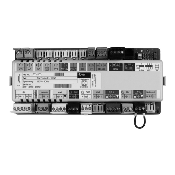
Page 19: Notes On Electrical Connection
NOTES ON ELECTRICAL CONNECTION Notes on electrical connection WARNING Make sure that no cables are live before starting wiring work. The mains voltage connections on the left side and the entire lower connector strip car- ries or might be carrying 230 volts. These ter- minals are not allowed to be touched when live: potentially fatal electric shock hazard. - Page 20 Conservation of Energy - Protection of the Environment...
Need help?
Do you have a question about the TopTronic E and is the answer not in the manual?
Questions and answers