Table of Contents
Advertisement
Advertisement
Table of Contents

Related Manuals for Reborn Endo R-SMART PLUS

Summary of Contents for Reborn Endo R-SMART PLUS
- Page 1 R-SMART PLUS ENDO MOTOR USER MANUAL Read the instruction manual before usage...
-
Page 2: Table Of Contents
Contents ························································································ Introduction ································································································ Notice ······························· ························································· 3 Installation ··············· ··························································· · 4 Operation ········································································ 5 Trouble shooting ············· ······················································ 6 Cleaning and Sterilization ···················································· 7 Storage, maintenance and transportation ································································ 8 Environmental protection ··············································································· 9 Warranty ······························································· 10 Standard symbols ···········································································... -
Page 3: Introduction
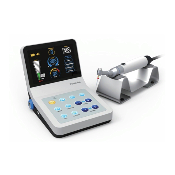
R-Smart Plus is composed of main unit, handpiece, contra-angle, measuring wire, file clip, measuring file, adapter and handpiece stand. 1.4 Intended use R-Smart Plus is an electronic device used for enlarging root canal. This product must only be used in hospital environments, clinics or dental offices by qualified dental personnel. - Page 4 been cautioned by their physicians against the use of small electric appliances such as shavers, hair dryers, etc. b) In patients allergic to metals. c) In children. 1.6 Components 1.6.1 The structural figure of the device. (Fig. 1.1) Screen Charging port Operation panel Handpiece Port Measuring wire port...
- Page 5 1.6.2 The figures of the main accessories. (Fig. 1.2) a Contra-angle b Motor handpiece c File clip d Adapter e Lip hook f Measuring file g Measuring wire h Single-head measuring wire i Silicon rubber case Fig. 1.2 The figure of the main accessories. 1.7 The classification of the device 1.7.1 Type of protection against electric shock: Class Ⅱinternally powered equipment.
-
Page 6: Notice
2 Notice 2.1 Please read the user manual carefully before the operation. 2.2 While being on operation, the scale indication on the R-SMART PLUS screen does not represent a distinct length or distance in mm or other linear units. It simply indicates the file progression towards the apex. - Page 7 a) Presence of portable or movable radio frequency transmitters in the surroundings. b) Electromagnetic interference could cause improper operation of the device. 2.5 This device has electromagnetic interference which is similar to other device, the patient or doctor who with a pacemaker are forbidden to use this device. 2.6 While being on operation, the apical position is located to the place apex locator screen indicates “00”, as a safety precaution in order to avoid over-instrumentation, it is recommended to subtract 0.5 mm-1.0mm to determine the working length for...
-
Page 8: Installation
3 Installation 3.1 Connecting the Contra-angle and Handpiece (Fig. 3.1) Contra-angle connector Contra-angle connector Locating point Locating point Fig. 3.1 Explanation of connecting the contra-angle and handpiece a) Before using this instrument, clean all the parts which may contact with patients. b) Only match the locating points of both contra-angle and handpiece, they can connect smoothly. - Page 9 Attention: Please don’t use the device when it is charging. 3.4 Automatic shutdown When not used for 5 minutes, R-Smart Plus will automatically shut down and all of the display and function are stopped. 3.5 Automatic calibration...
-
Page 10: Operation
4 Operation 4.1 R-Smart Plus function definition (Fig. 4.1/4.2) Storage key Volume key Charging sign Power key Apex setting key POWER Program key Speed setting Mode key Motor forward/reversed Torque setting switch key Motor working mode key Fig. 4.1 Explanation of operation panel... - Page 11 4.2 Specific Instructions POWER: Switches the device on or off (LCD screen lights up or goes out) VOLUME: Adjusts the sound volume or mute STORAGE: Saves the current setting data of speed, torque, auto reverse and root tip limit value into program APEX SETTING: Sets the root location (in M4 mode, file will be auto reverse when arrives the pre-set root location ) MODE: Switches the 4 operation modes...
- Page 12 File will stop when the stress is more than setting torque data. When the stress is more than setting torque data, file will auto reverse. If remove the stress, file will stop. When the stress is more than setting torque data, file will auto reverse.
- Page 13 Fig.4.3 Fig.4.4 Attention: Do not draw the wire when inserting or pulling out measuring wire. (Fig. 4.4a incorrect operation. 4.4b correct operation.) a)Make sure the measuring wire is inserted correctly. b)Make sure the measuring wire is connected with file clip and lip hook. c)Make the lip hook touch the bent wire of the file clip (as showed in Fig.
- Page 14 Fig.4.6 Explanation of the interfaces displayed a) The white region of instruction bars on the screen is the front region of the apical foramen. (Fig. 4.6a) b) The file position is near by the apical foramen when the green bars displayed. (Fig.
- Page 15 corner of mouth File File handle Metallic part of file 1.Push by thumb to the arrow direction Working and moving part of file 2.Clamp the file (Do not clamp on this part) 3.Release the thumb Fig. 4.7 When the file reaches the apical position, adjust the rubber piece of the file set to the reference point (incisal edge or fossa edge), then pull out the file, measure the length between the file tip and the rubber piece.
- Page 16 e) Press the key on handpiece to start working. f) Torque value will be displayed on screen when working. (Fig. 4.9) g) Press switch button to switch direction of rotation. Torque bar Pre-set root location Fig. 4.9 Fig. 4.10 4.5 Installation and operation of M3 a) Same way to install and switch on handpiece as mode M2.
- Page 17 4.7 Installation and operation of M5 a)Same way to install on handpiece as mode M3. b)Same settings of rotation speed and torque as mode M3. c)Press APEX key to set the apex location. (Fig. 4.10) d)Wear the silicon rubber case, and insert the single-head measuring wire into handpiece, then insert the lip hook into the socket of the single-head measuring wire to hang the lip hook on the mouth of patient.
-
Page 18: Trouble Shooting
5 Trouble Shooting Problems Possible caues Solutions 1 The incorrect battery 1 Install the battery correctly. No displays on the installation. 2. Recharge the battery. screen after turning 2 The lower power. 1.Handpiece and main 1. Check the connection. unit are not connected. 2.Set a higher torque. - Page 19 Problems Possible caues Solutions 1.Endo file does not enter 1.Endo file need to enter root the root canal canal 2.Root canal is too dry 2.Drip into proper saline 3.A poor connection of file 3.Remove contamination or Endo file doesn’t clip or measuring wire replace spare part work in mode 4.
-
Page 20: Cleaning And Sterilization
6 Cleaning and Sterilization 6.1 After use, all parts that have contacted with the patients should be wiped by sterilized towel. (no bacteria, no fungi and no aldehyde liquid) 6.2 Cleaning with chemical reagents may cause damage to the instrument. 6.3 Contra angle, lip hook, clip and probe must be autoclaved before use. -
Page 21: Environmental Protection
The product does not contain harmful ingredients. Please handle base on local disposal policy. 9 Warranty R-Smart Plus is warranted for 24 months from the date of purchase. The accessories (cables, battery etc.) are warranted for 6 months from the date of purchase. Please contact your local distributor for maintenance. -
Page 22: Statement
Recovery Keep dry Storage relative humidity Handle with care less than 85%RH Storage atmospheric Storage temperature at pressure at 70kPa~106kPa -10℃~+50℃ Handle interface Measuring wire interface Deal with the product according to the WEEE (2002/96/EC) 11 Statement All rights of modifying the product are reserved to the manufacturer without further notice.
Need help?
Do you have a question about the R-SMART PLUS and is the answer not in the manual?
Questions and answers