
Related Manuals for ePropulsion NAVY


Summary of Contents for ePropulsion NAVY
- Page 1 NAVY REMOTE CONTROL USER MANUAL Nov, 2018 Version 1.0 Copyright © 2018 ePropulsion All Rights Reserved...
-
Page 3: Acknowledgement
By using this product, you hereby agree that you have fully read and understood all contents of this manual. ePropulsion accepts no liability for any damage or injury caused by operations that contradict this manual. -
Page 4: Product Identification
Product Identification Below picture indicates the serial numbers of NAVY Remote Control. Please note the position of the serial numbers and record them for access to warranty service and other after-sale services. Model: NAVY Remote Controller Serial No.: DNRCXXXXXXX Figure 0-1... -
Page 5: Table Of Contents
Table of Contents Acknowledgement ..................1 Using This Manual ..................1 Symbols ...................... 1 Product Identification ................2 Table of Contents ..................3 1 Product Overview ..................4 1.1 In the Package .................. 4 1.2 Parts and Diagrams ................5 1.3 Specification .................. -
Page 6: Product Overview
Remote Control, it requires an additional steering wheel to help steer. 1.1 In the Package When you receive a set of NAVY Remote Control, unpack its package and check if all the items below are included in the package. If there is any loss or transport damage, please contact your dealer immediately. -
Page 7: Parts And Diagrams
Display Panel Buttons Solar Panel Kill Switch Communication Port (Bottom) Figure 1-1 1.3 Specification NAVY Remote Control Communication Wireless / Wired Communication Distance ≤10 m Weight 0.65 kg / 1.43 lbs. 193 mm x 130 mm x 112 mm / Dimension (L x W x H) 7.6"... -
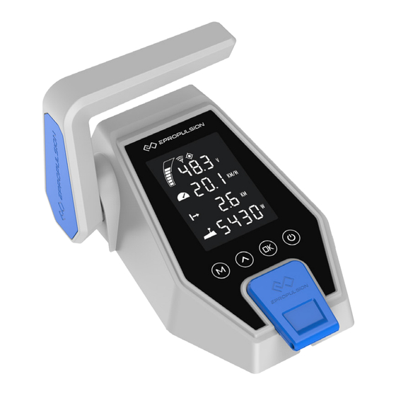
Page 8: Displaying
2 Displaying GPS Status Indicator Overheat Alert Kill Switch Status Indicator Battery Level Indicator Battery Level/Voltage Travelled Distance/ Current Speed Time or Remaining Distance/Time Distance/Time Throttle Reset Indicator Throttle Power Figure 2-1 Buttons Functions 1. In power-off state, press and hold the power button to power on the Remote Control. - Page 9 Buttons Functions 1. On any setting page, press “ ” button to view options for current setting. 2. In power-on state, when home page displays, press “ ” button and hold 10s to enter the throttle calibration page. 3. On home page, press “ ”...
- Page 10 If users enter the page without setting any parameters, the current parameters displayed on the page will be saved as user parameters by default. If “ ” shows on start - up, it indicates system initialization. Icons Functions Battery level Indicating approximate battery level.
- Page 11 Icons Functions Hidden: kill switch is present and is working well. Kill switch status indicator Shown constantly: the kill switch is detached. Displaying real time cruising speed. Set units (KM/H, MPH or KNOTS) in Current speed preference setting page. Displaying real time travel distance/time. Distance/time Set units (MILE, KM (kilometer) and NM display...
-
Page 12: Charging
3 Charging The NAVY Remote Control has a built-in lithium battery for power supply. The battery will be charged automatically under normal use: get charged by solar power or wired connection. 3.1 Charging by solar power When the solar panel receives enough sunshine, it will generate electricity to charge the built-in lithium battery. - Page 13 Please follow the below steps to charge the Remote Control by wired connection. First, connect the Remote Control to the outboard motor by a communication cable first (Figure 3-3); Then, connect the outboard motor to the battery. Communication Cable * The communication cable needs to be purchased separately.
-
Page 14: Power Adjusting
Forward Neutral Backward Figure 4-1 Outboard motor Forward power Backward power NAVY 3.0 3 kW 3 kW NAVY 6.0 6 kW 4 kW Before power on the Remote Control, please reset the throttle to neutral position. -
Page 15: Adjusting Maximum Forward/Backward Power
4.2 Adjusting Maximum Forward/Backward Power Users can set the maximum forward/backward throttle power on their own. Make sure the battery is powered off before adjusting. Step 1: Turn on the Remote Control. The home page displays. Step 2: Long press (5s) “ ”... -
Page 16: Recalibration
4.3 Recalibration The throttle position sensor should be recalibrated if the below error code displays. Figure 4-3 Recalibration process LCD Displaying Step1: Long press “ ” button for 10s until “CAL FO” displays. Step2: Push the throttle to the maximum forward power position, then press “... - Page 17 Step4: Pull the throttle to the maximum backward power position, then press “ ” button. “CAL FO” will display and calibration is completed. A blinking “RESET” will display to remind you to reset the throttle to zero position. Step5: Push the throttle to zero position and press the “...
-
Page 18: Use Of Kill Switch
5 Use of Kill Switch Locate the kill switch to the right place on the Remote Control and tie its lanyard to your wrist or life jacket. Stop the outboard in emergency by detaching the kill switch. To run the motor again, first attach the kill switch then start the motor. Figure 5-1 The kill switch generates magnetic field. -
Page 19: Pairing Remote Control To The Outboard
” (set), and a countdown timer “ ” (60s). Figure 6-1 Step4: Switch on NAVY power. Wait for them to get paired in a few seconds. Step5: After pairing, the LCD screen will display as Figure 6-2 for 5s, then returning to home page automatically. - Page 20 Step3: Switch on both NAVY outboard and Remote Control and wait for them to get paired. Step4: Pairing succeeds until home page displays. Then disconnect the communication cable. Main Switch Figure 6-3 c. Pairing by Communication Cable with a NAVY Battery Step1: First connect the main switch cables to the NAVY Battery.
- Page 21 ③ ② Remote Control ④ Communication Cable Main Switch ③ ① Figure 6-4 If the outboard is replaced with a new one, the original wireless link will break and wireless communication failure will occur. The main page of the LCD panel on the Remote Control will display as below. In this case, users should conduct pairing again.
-
Page 22: Warning Messages
7 Warning Messages When the outboard motor is running in abnormal conditions or out of order, a warning message with an error code will display on the LCD screen. Figure 7-1 is an example. Please find more error codes and corresponding solutions in the below table. - Page 23 NAVY Battery is Charge NAVY Battery running out of power Communication Check if the communication cable Error between NAVY between NAVY outboard and NAVY outboard and NAVY battery is well connected, if yes, please battery restart the system.
- Page 24 Please refer to section 6 Pairing Remote characters Device addresses Control to the Outboard Motor and pair display mismatch. the Remote Control with the outboard motor again. If the problem persists, please consult your ePropulsion authorized dealer for assistance.
-
Page 25: Warranty
8 Warranty The ePropulsion limited warranty is provided for the first end purchaser of an ePropulsion product. Consumers are entitled to a free repair or replacement of defective parts or parts which do not conform with the sales contract. This warranty operates in addition to your statutory rights under your local consumer law. -
Page 26: Out Of Warranty
1. Fill in Warranty Card correctly and completely in advance. Then make your warranty claim by sending it to your authorized ePropulsion service partner together with valid proof of purchase. Usually these documents are required when making a warranty claim: the Warranty Card, ex-factory serial number, and evidence of purchase. - Page 27 3. The defective components or parts will be either repaired or replaced according to the diagnosis made by the ePropulsion authorized service partner. 4. If your warranty claim is accepted, the equipment will be repaired or replaced free of charge. Note that any delivery cost incurred in the process is at your charge.
- Page 29 Thanks for reading this user manual. If you have any concerns or find any problems while reading, please don't hesitate to contact us. We are delighted to offer service for you. Dongguan ePropulsion Intelligence Technology Limited Website: www.epropulsion.com Email: service@epropulsion.com...
Need help?
Do you have a question about the NAVY and is the answer not in the manual?
Questions and answers