Table of Contents
Advertisement
Quick Links
User Manual and Installation Guide
(Applies to both DR600-DFT and DR600-OFD versions)
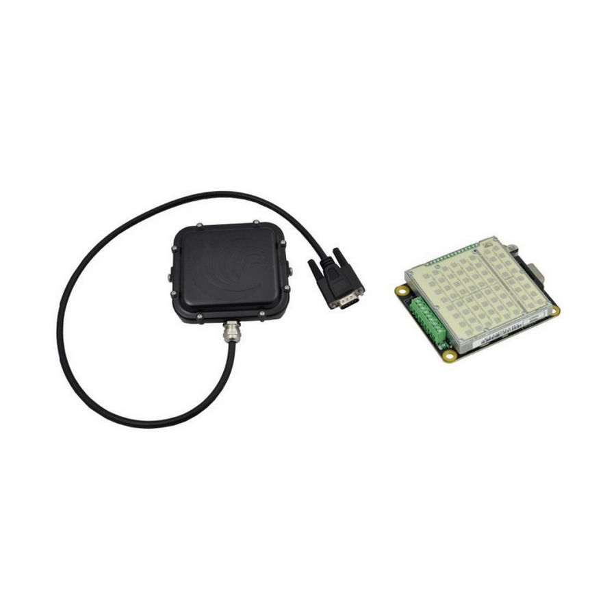
DR600 in weatherproof enclosure
Version (DR600-DFT)
Houston Radar LLC
12818 Century Dr. Stafford, TX 77477
Http://www.Houston-Radar.com
Email:
sales@Houston-Radar.com
Contact: 1-888-602-3111
DR600
K-Band Doppler Radar DR600
th
Rev 1, 11
January 2019
Page 1 of 35
DR600 open frame
Version (DR600-OFD)
Advertisement
Table of Contents

Related Manuals for Houston Radar DR600

Summary of Contents for Houston Radar DR600
- Page 1 DR600 User Manual and Installation Guide K-Band Doppler Radar DR600 (Applies to both DR600-DFT and DR600-OFD versions) Rev 1, 11 January 2019 DR600 in weatherproof enclosure DR600 open frame Version (DR600-DFT) Version (DR600-OFD) Houston Radar LLC 12818 Century Dr. Stafford, TX 77477 Http://www.Houston-Radar.com...
- Page 2 Changes or modifications not approved by Houston Radar could void the user’s authority to operate the equipment. Note: This equipment has been tested and found to comply with the limits for Class B digital device, pursuant to part 15 of the FCC Rules.
- Page 3 2. cet appareil doit accepter Toute interférence, y compris les interférences qui peuvent causer un mauvais fonctionnement du dispositive. Warning: DR600-OFD radar is supplied in an open frame format with exposed antenna and electronics and thus is a static sensitive device. Please use static precautions when handling.
-
Page 4: Table Of Contents
USE ........................... 12 Internal Clock: ......................13 Configuring the Unit: ....................13 Configuring the Radar with Houston Radar Stats Analyzer GUI: ......17 STEP 1: Connect to Radar ..................18 STEP 2: DR600 Setup ....................19 STEP 3: Select the radar units .................. 20 STEP 4: Set the radar cutoff speeds (low and high speed cutoff) ...... -
Page 5: Introduction
INTRODUCTION Congratulations on your purchase of the Houston Radar directional Doppler Speed Radar DR600. This state of the art 24GHz K-band microwave Doppler radar is specifically designed for the license free battery operated speed measurement and monitoring market. Utilizing high performance, ultra-low power DSP (Digital Signal Processing) technology,... -
Page 6: Direction Pointing
Direction Pointing: The DR600 is directional in nature. It may be configured to detect and measure the speed of incoming, outgoing, or bi-directional traffic. It then rejects traffic moving in the opposite direction (unless set to bi-directional). -
Page 7: Hookup
ON via a bit in the “MD” variable. This can also be configured through the GUI. Measured Speed Output: The DR600 will send out the measured speed via the ASCII interface as a 3 digit speed with an optional direction indicator. The format is: [?,+]nnn[.ddd][\r,\n] The format of the speed output can be adjusted to any combination of: “?”: Optional prefix sent when 000 selected to be sent when no vehicles are detected... -
Page 8: Setting Variables From An Ascii Terminal Program Via Ascii Commands
At least one or both of the line endings must be selected with ASCII format. No line ending is not an option. Please see serial port configuration section for details on how to select the above format. Alternatively, the radar may be set to output a single byte speed in binary format. No line termination is issued when format is set to binary. - Page 9 set:LO=5 sets the low speed cutoff to 5 etc. To get a variable (variables are documented in the user manual): get:<case sensitive variable name>[ENTER] e.g. get:LO returns LO=5 (if value is presently set to 5). If sending the ASCII command via an attached microcontroller, the “[ENTER]” key press should be replaced by the carriage return and/or line feed ASCII charact Page 9 of 35...
-
Page 10: Wire Signal Descriptions (Terminal Block)
Houston Radar DR600 User Manual Wire Signal Descriptions (Terminal Block): Molex Wire Signal Direction Connector Description Color Name (wrt Radar) Pin # VCC Power Supply Green Output RS232 Transmit Signal from radar Gray Input RS232 Receive Signal into radar Brown... - Page 11 The DR600 features two low impedance outputs that can trigger/turn on an external display/device to bring it out of power saving mode when a vehicle is detected.
-
Page 12: Use
Houston Radar DR600 User Manual Turn on the power to the DR600 to make it operational. No other action is required. The radar will typically activate OUT 1 and OUT 2 open drain outputs whenever it detects a vehicle that is above the programmed lower speed limit (the “LO” value) and below the programmed high limit (the “HI”... -
Page 13: Internal Clock
The DR600 radar features a built in clock backup battery that will keep the clock time in the case of power failure for over 10 years. Configuring the Unit: The radar’s internal parameters may be configured via the radar’s RS232 port after... - Page 14 Bit 1: Enable ASCII console output on primary RS232 serial port. Bit 2: Enable ASCII console output on auxiliary RS232 serial port. Bit 3 to 7: Reserved in DR600 radar. Bit 8: Disable power optimized mode. RF ON all the time.
- Page 15 Houston Radar DR600 User Manual Bit 13 to 14: Reserved in DR600 radar. Bit 15: Enable individual vehicle statistics records (requires statistics). Radar IO configuration bitmask. Bits are as follows: Bit 0: Reserved in DR600 radar. Bit 1: Set: IO 1 Active high. Clear: IO 1 active low.
- Page 16 Houston Radar DR600 User Manual 1: Outgoing 2: Bi-directional Radar cycle time in ms. Valid values include 50-1000ms. As cycle time decreases, power increases. Range is decreased by approximately 30% if cycle time is less than 115ms, and 50% if cycle time is less than 85ms.
-
Page 17: Configuring The Radar With Houston Radar Stats Analyzer Gui
USB-RS-P1 powered USB dongle (shown above). This device connects to a USB port on a Windows computer and provides an RS232 connection and 12VDC power to all Houston Radar devices. You can be up and taking to the radar within a few minutes of receiving your device. -
Page 18: Step 1: Connect To Radar
Houston Radar DR600 User Manual STEP 1: Connect to Radar Select your COM port (or “AutoDetect Port” option) and then click on “Connect To Radar”. Click “OK” on the next two boxes. The box on the left shows you information about the radar that you have connected to. -
Page 19: Step 2: Dr600 Setup
Houston Radar DR600 User Manual STEP 2: DR600 Setup Click on “DR600 Setup” to bring up the configuration GUI. You can then set various options in the radar via the different tabs shown here. You must click the “Save Changes” button for your changes to be saved to the radar. -
Page 20: Step 3: Select The Radar Units
Houston Radar DR600 User Manual STEP 3: Select the radar units Radar units apply to the speed output over the RS232 serial port as well the low limit cutoff and high limit cutoff settings. Additionally, if traffic statistics gathering is enabled, statistics are saved in integer mph boundary speed bins for mph and ft/sec units and in km/h integer boundary speed bins for km/h or m/s units in the radar. -
Page 21: Step 4: Set The Radar Cutoff Speeds (Low And High Speed Cutoff)
Houston Radar DR600 User Manual STEP 4: Set the radar cutoff speeds (low and high speed cutoff) Cutoff speeds affect the measurement range for sending speed out over the serial port and activation of the hardware trigger outputs. Cutoff speeds do not affect collection of traffic statistics in the radar. Traffic statistics are always collected over the entire measurement range of the radar. -
Page 22: Step 5: Set Detection Sensitivity
Houston Radar DR600 User Manual STEP 5: Set Detection Sensitivity You can adjust the radar sensitivity by entering a value, clicking the up/down arrows, or moving the slider. The sensitivity can be reduced if you wish to restrict the pickup range of the radar. -
Page 23: Step 6: Set Detection Direction & Target Selector
Houston Radar DR600 User Manual STEP 6: Set Detection Direction & Target Selector The radar detects multiple targets internally, but only outputs the speed of one. This setting instructs the radar to pick either the fastest speed or the speed associated with the strongest return signal. -
Page 24: Step 7: Set "Slow Speed Targets Filter" And "Tuning Fork Test" Modes
Houston Radar DR600 User Manual STEP 7: Set “Slow Speed Targets Filter” and “Tuning Fork Test” Modes If you wish to improve rejection of rain pickup and other low speed “noise” that the radar may pick up, enable this option. -
Page 25: Step 8: Setup Baud Rate, Ascii Format, And Output Precision
“Enable Speed Output” option tells the radar to send wish to receive in the speed output. The out speeds when a target is detected. DR600 can output speeds with up to 3 decimal points of precision. “Disable Countup” option speeds up startup times by about 3 seconds by suppressing the default 0 through 10 count-up output over the serial port. -
Page 26: Step 9: Select Speed Output Interval
Houston Radar DR600 User Manual STEP 9: Select Speed Output Interval You can change the speed output time interval by entering a value or moving the slider. Click the “Set Stats Compatible Interval” button to set the update interval to the default value. All other values will disable statistics if you have a statistics enabled radar. -
Page 27: Step 10: Select Speed Measurement Mode
Contact us for more details. If you have purchased the Advanced In-Radar traffic statistics option, the DR600 can be set to output either real-time target speeds over the serial port, or internally average all traffic speeds over a specified interval (say 30 seconds) and output the average speed. -
Page 28: Step 11: Configure The Trigger Outputs
The DR600 has two hardware “open drain” trigger outputs that may be used to trigger an external device or turn on 1 or 2 LED lamps to make a stand-alone speed enabled flasher or VATCS (Vehicle Activated Traffic Calming Sign). - Page 29 Houston Radar DR600 User Manual Output Hold Time: Set a value here if you want to hold or extend the trigger when it’s activated. This is useful to turn ON an external device for a minimum amount of time when triggered by the radar.
-
Page 30: Step 12: Select Rs232 (Serial Data Output) Mode
STEP 12: Select RS232 (serial data output) mode The DR600 radar turns off the internal RS232 serial driver if it does not detect any RS232 voltage level on the RX pin. It automatically powers this chip back up once you plug in a RS232 cable. -
Page 31: Step 13: Optional Advanced In-Radar Traffic Statistics Logging
Houston Radar DR600 User Manual STEP 13: Optional Advanced In-Radar Traffic Statistics logging If statistics logging is enabled in your radar (a separate purchase option), select how long you wish the radar to collect data in speed bins before it saves off the log to internal flash memory and starts a new record. -
Page 32: Dr600 Specifications
50ms Update Rate: 23.5 mA avg (+/-1mA) (@+12V DC) Operating Temp. -22F to +176F (-30C to +80C). Electronics designed and tested to –40C. Weatherproof Yes (DR600-DFT build option). Open frame also available. Approvals Approvals FCC Part 15 (US Version) FCC ID TIADR600... -
Page 33: Performance
Houston Radar DR600 User Manual Performance Speed Measurement Range 0.6mph to 206 mph (0.97km/h to 331 km/h). 0.003 mph Resolution 0.5% of reading + 0.1mph Accuracy Detection Range In non-range boost mode, typically 450+ m (1500+ feet) for compact vehicles on open and level road with radar mounted 1.5 m (5 feet) high and pointed straight into... -
Page 34: Ordering Options
Houston Radar DR600 User Manual Ordering Options Order Code Description Field Connection Mounting Right side via terminal 4x holes for up to #8- DR600-OFD Open Frame block, or left side via 32 size screws Encapsulated 2x #8-32 ¼” DR600-DFT Male DB9... -
Page 35: Appendix A: Connecting To The Radar Trigger Outputs
Houston Radar DR600 User Manual Appendix A: Connecting to the radar trigger outputs The DR600 radar features two current and voltage limited “open drain” outputs. The two outputs OD1 and OD2 are brought out on the DB9 connector pins 7 and 8. As well as the labelled terminal block (if installed).
Need help?
Do you have a question about the DR600 and is the answer not in the manual?
Questions and answers