
Related Manuals for Raytheon NSC 18


Summary of Contents for Raytheon NSC 18
- Page 1 NSC 18 Navigational Radar System User Manual 3748DOC020102 Edition 14.JAN.2005 3464 100 – 037...
- Page 2 Weitergabe sowie Vervielfältigung dieser Unterlage, Verwertung und Mitteilung ihres Inhaltes nicht gestattet, soweit nicht ausdrücklich zugestanden. Zuwiderhandlungen verpflichten zu Schadenersatz. Copying of this document, and giving it to others and the use or communication of the contents thereof, are forbidden without express authority.
-
Page 6: Table Of Contents
NSC 18 RADAR Raytheon Marine GmbH Operator Manual Germany Table of Contents Introduction ............. . - Page 7 Operator Manual Table of Contents 2.3.3 Radar video settings ........... . . 2−43 2.3.3.1 Range RNG .
- Page 8 NSC 18 RADAR Raytheon Marine GmbH Operator Manual Germany Table of Contents 2.4.12 Reference target ON/OFF ..........
- Page 9 Operator Manual Table of Contents Automatic Radar Plotting Aid (ARPA) ........3−14 3.4.1 Sensor Errors...
- Page 10 List of Abbreviations ACP, Azimuth Commit Point MTR, Modulator Transmitter Receiver ARPA, Automatic Plotting Aid ARP, Azimuth Reset Point N−UP, North−Up NM, Nautical Miles BRG, Bearing PCP, Potential Collision Point CPA, Closest Point of Appoach PMU, Performance Monitor Unit C−UP, Course Up POS, Position CSE, Course PPI, Plan Position Indicator...
- Page 11 List of Abbreviations T−SCE, Test scenario TCM, Transceiver control module, TN, Tune TTG, Time to go Tx, Transceiver ON TCPA, Time of Closest Point of Approach TM, True Motion TRU, True TTG, Time To Go TFT, Thin Film Transistor VRM, Variable Range Marker XCVR, Transceiver unit...
- Page 12 NSC 18 RADAR Raytheon Marine GmbH Operator Manual Germany QUICK STARTUP GUIDE STDBY/TX MODE RM (T) TRAILS TRUE RECOMMENDED SPEED LOG (WT) USER ADJUSTMENTS AFTER VECTOR TRUE SWITCHING ON THE NSC RADAR FILTER (KEY) ECHO EXP Cursor ANTI−COLLISION AREAS Trackball...
-
Page 13: Gyro Compass
Raytheon Marine GmbH SHORT OPERATION Germany Radar Video Information MenuBar SWITCH ON THE RADAR, Radar Video SITUATION SETTINGS see chapter 2.3.2.1 settings panel see chapter displays SELECT THE BEST PRESETTINGS see chapter 2.3.2 see chapter 2.3.3 see chapter 2.3.6 2.3.6.6 Switch ON the NSC. - Page 14 NSC 18 RADAR Raytheon Marine GmbH Operator Manual Germany IMPORTANT NOTICE AND SAFETY INFORMATIONS This Radar is an aid to navigation. Its accuracy can be affected by many factors such as equipment defect, environmental conditions, or improper operation. It is the user’s responsibility to exercise common prudence and navigational judgement at all times.
- Page 15 Operator Manual HIGH VOLTAGE There is absolutely no danger in handling the external controls of the radar while the radar is in operation. In the radar‘s interior, however, are high voltages which are fatally dangerous to anyone careless handling interior components.
- Page 16 NSC 18 RADAR Raytheon Marine GmbH Operator Manual Germany MICROWAVE RADIATION A short exposure to the microwaves radiated by the radar antenna is harmless. However, avoid prolonged exposure to the microwaves. Never look directly into the wave guide while checking transceiver operation, since microwaves are especially harmful to the eyes.
-
Page 17: Introduction
Operator Manual Introduction The Operator Manual An operator should become familiar with the location of the display information and the control panel buttons. Manual overview. Glossary of Terms chapter 1 for important safety notes for showing the NSC Radar System chapter 2 for operation short operation... -
Page 18: Radar System
NSC 18 RADAR Raytheon Marine GmbH Operator Manual Germany Radar System 10 kW X−band antenna unit (6 feet array) NSC 18 Radar Display connection board Option: Can Bus Power 24V DC Gyro−Interface possible signal inputs for Sperry/Synchro (NMEA I/O): Step Input... -
Page 19: Operating Instructions
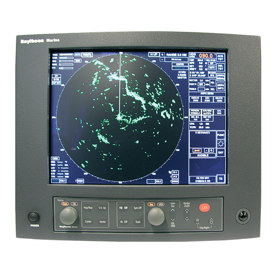
NSC 18 RADAR Raytheon Marine GmbH Operator Manual Germany OPERATING INSTRUCTIONS Three components are essential for operation of the NSC 18 Display Trackball Radar control panel Figure: 2−1 NSC Radar components for operation Display The display is a high−resolution TFT (Thin Film Transistor) flat screen color monitor. -
Page 20: Display Organization And Submenu Structure
Operator Manual DISPLAY ORGANIZATION AND SUBMENU STRUCTURE The following figures provide an overview of the organization of the NSC display and its submenu structure. Radar video Radar video INFORMATION displays, settings, PANEL, see chapter 2.3.2 see chapter 2.3.3 see chapter 2.3.6 MENU bar, see chapter 2.3.2.1... - Page 21 NSC 18 RADAR Raytheon Marine GmbH Operator Manual Germany Figure: 2−3 Display and submenu organization 2−3 Edition: 14.JAN.2005 3748DOC020102...
- Page 22 Operator Manual Figure: 2−4 Display and organization of AIS INFO and ARPA MENUs 2−4 3748DOC020102 Edition: 14.JAN.2005...
- Page 23 NSC 18 RADAR Raytheon Marine GmbH Operator Manual Germany Figure: 2−5 Display of ARPA submenu and selected functions 2−5 Edition: 14.JAN.2005 3748DOC020102...
- Page 24 Operator Manual Figure: 2−6 Display of FUNCtion submenu and selected functions 2−6 3748DOC020102 Edition: 14.JAN.2005...
-
Page 25: First Steps In Operation
NSC 18 RADAR Raytheon Marine GmbH Operator Manual Germany FIRST STEPS IN OPERATION This chapter describes following basic functions D Switching ON the NSC radar system, STANDBY mode, synchronization setting of the heading signal (see chapter 2.2.1) D How to use the CURSOR (see chapter 2.2.2) D How to handle the RADAR OPERATOR PANEL (see chapter 2.2.3) -
Page 26: Switching On
Operator Manual 2.2.1 Switching ON Positioned on front, lower left side. Power button Pressing the button switches on the power. D The Radar Utility Selector window appears in the display. RADAR Select the RADAR softkey in the window and press the Left button on the trackball. - Page 27 NSC 18 RADAR Raytheon Marine GmbH Operator Manual Germany Operating hours Modulator counter transmitter− receiver (XCVR...) assignment Radar display as- signment . . . Figure: 2−7 NSC Radar in STANDBY mode −System configuration diagram − STBY Switching the radar ON Using the trackball, place the cursor on the STBY softkey and press the Left button on the trackball.
-
Page 28: How To Use The Cursor
Operator Manual 2.2.2 How to use the CURSOR When using the trackball, the cursor is moved by rolling the ball in the appropriate direction. The trackball−guided cursor is the central control for using this radar. Figure: 2−8 Trackball The trackball is equipped with two buttons. This button is used as the Left button. -
Page 29: Cursor In Park Position
NSC 18 RADAR Raytheon Marine GmbH Operator Manual Germany 2.2.2.1 Cursor in park position This function is selectable. Select the CURS button, the CURSOR READOUT displays in the function display. MOUSE PARK POSITION ON means; If you do not use the cursor for some time, it jumps automatically into park position outside the radar video area, see Figure: 2−14. -
Page 30: Cursor Symbols
Operator Manual 2.2.2.2 Cursor symbols Figure: 2−9 Cursors illustrate the various cursor symbols that will be seen when using the NSC display. DEFAULT CURSOR OFFSET CURSOR second cursor symbol (in red) appears in the radar video if the NSC Radar and the NSC ECDIS are combined as a system Figure: 2−9 Cursor symbols 2−12... -
Page 31: Radar Operator Panel
NSC 18 RADAR Raytheon Marine GmbH Operator Manual Germany 2.2.3 Radar operator panel The radar operator panel is designed to execute the most commonly used functions. Signaling: Illumination of the buttons and status indicators is switched on when the relevant action is activated. - Page 32 Operator Manual Hides the symbols in the radar video. Press the button and the artificial symbols will disappear. Press again to show the symbols. Symbols are EBLs, VRMs, PL, ARPA zones, MAPs. Status indicators, press toggle switch (7). The activated function is indicated by ).
-
Page 33: Softkeys And Operator Controls In Nsc Display
NSC 18 RADAR Raytheon Marine GmbH Operator Manual Germany 2.2.4 Softkeys and operator controls in NSC display 2.2.4.1 Softkeys in menu bar The text on the softkeys always describes the current mode status. Example: means that the radar is in DAY mode STBY means that the radar is in Standby mode Clicking on the software button changes the status. - Page 34 Operator Manual D To find the optimum brightness for the visual features of the PPI and for the visual features located around the PPI (see chapter 2.3.6.6). D This softkey function allows you to choose whether the NSC operates in DAY NIGHT mode or in NIGHT mode (see chapter 2.3.6.6).
-
Page 35: Operator Controls In Nsc Display
NSC 18 RADAR Raytheon Marine GmbH Operator Manual Germany 2.2.4.2 Operator controls in NSC display To handle this NSC display, you need to use certain built−in operator controls. These operator controls are as follows: Operator controls Text identifier Softkey Toggle fields... -
Page 36: Toggle Fields
Operator Manual 2.2.4.3 Toggle fields The toggle field functionalities are called up by pressing the trackball buttons or alternatively (partially) using the buttons on the operator panel. Example: − The range is increased by clicking on the (+) button and decreased using the (−) button. - Page 37 NSC 18 RADAR Raytheon Marine GmbH Operator Manual Germany Toggle field with slider ° 127.9 EBL2 Position the cursor on the toggle field, press and hold the trackball button. A slider appears below the toggle field. Left The slider can make an analog movement in the desired direction using the Press trackball.
-
Page 38: Drag And Drop
Operator Manual 2.2.4.5 Drag and drop This cursor controlled operation is used in radar video; e.g. if an acquisition zone is to be changed. Pick up: Position the cursor on the zone Right Press once The zone is now shown in a dotted form, editing markers are shown at the corners. -
Page 39: System Reset
NSC 18 RADAR Raytheon Marine GmbH Operator Manual Germany 2.2.5 System reset When a system reset is carried out, only the NSC software is re−initialized; the transceiver remains actuated. Power ON/OFF button Procedure: Trigger the system reset. Press the dipswitch briefly with a pointed object. -
Page 40: Switching Off The Nsc Radar System
Service Switch to Admin + password Service Switch to Admin + password Service Report Export to USB Service Report Export to USB Service Raytheon Update from USB memory Service Raytheon Update from USB memory Service Display Resolution Service Display Resolution... - Page 41 NSC 18 RADAR Raytheon Marine GmbH Operator Manual Germany Power button Press the power button for approx. 4s. The process is complete. 2−23 Edition: 14.JAN.2005 3748DOC020102...
-
Page 42: Display Operations And Indicators
Operator Manual DISPLAY OPERATIONS AND INDICATORS This chapter describes the function sections of the NSC display see Figure: 2−14. Radar video Radar video INFORMATION displays, settings, PANEL, see chapter 2.3.2 see chapter 2.3.3 see chapter 2.3.6 MENU see chapter 2.3.2.1 bar, Antenna sensitivity controls,... -
Page 43: Sensitivity Controls
NSC 18 RADAR Raytheon Marine GmbH Operator Manual Germany 2.3.1 Sensitivity controls 2.3.1.1 Gain and clutter processing The NSC uses a digital video processing technique called Scan to Scan integration or field processing. This process requires 3 complete antenna rotations or scans of the antenna in order to build up or decay detected targets. - Page 44 Operator Manual The tip of the tuning bar (yellow color) remains at the peak signal detected during one complete revolution of the antenna. NOTE Bear in mind the fact that the transmitter frequency will drift for the first thirty (30) minutes of operation from a cold start due to inherent magnetron characteristics.
-
Page 45: Gain
NSC 18 RADAR Raytheon Marine GmbH Operator Manual Germany 2.3.1.3 GAIN The GAIN control adjusts the sensitivity of the radar video. If properly adjusted, the GAIN control results in noise appearing as a light speckle at the dim level. This light speckle setting results in maximum detectability of targets against background noise. -
Page 46: Speed Log
Operator Manual The effect of the Sea control is at its greatest at short range. Its effect reduces progressively as the range increases. At a range determined by the height of the radar antenna above the water (and other factors), the effect of the SEA control ceases altogether. -
Page 47: Rain Rate
NSC 18 RADAR Raytheon Marine GmbH Operator Manual Germany 2.3.1.5 RAIN RATE Step 1 Step 1 Step 1 Select MANual mode Step 2 Step 2 The function of the RAIN control is to enable the operator to suppress radar returns which are the result of radar signals reflected from rain drops. -
Page 48: Filtering Rain Clouds Ftc
Operator Manual 2.3.1.6 Filtering rain clouds FTC Step 1 Select MANual mode Step 1 Step 2 Step 2 FTC is responsible for differentiation or filtering of rain clouds. Advance the FTC control slowly (remember the 3 scans) until only the leading edges of the rain clutter are visible. -
Page 49: Search And Rescue Transponder Sart On/Off (Option)
NSC 18 RADAR Raytheon Marine GmbH Operator Manual Germany 2.3.1.8 Search and rescue transponder SART ON/OFF (option) The SART ON/OFF does not activate ownship SART. It changes receiver bandwidth to improve SART detection by this radar. Information about the SART transponder The purpose of the SART is to trigger a secondary alarm when search and rescue units are searching for a life raft/lifeboat in distress. - Page 50 Operator Manual The SART transponder is in the immediate vicinity. Figure: 2−16 SART transponder 1 NM The SART transponder is in the vicinity. Figure: 2−17 SART transponder > 2 NM The SART transponder is a long distance away. 2−32 3748DOC020102 Edition: 14.JAN.2005...
-
Page 51: Pulse Width Selection
NSC 18 RADAR Raytheon Marine GmbH Operator Manual Germany 2.3.1.9 Pulse width selection The pulse width toggle field allows selection of the desired transmitter pulse width for the current range scale selected. If there is no pulse width toggle field, this indicates that it is not available for the range currently being used. -
Page 52: Interference Selection
Operator Manual 2.3.1.10 Interference selection The interference toggle field allows selection of the function interference ON or OFF. The function of interference rejection is activated to eliminate echo effects caused by other radar system from ships nearby. 2.3.1.11 Echo expansion By selection this toggle field, the function of echo expansion is activated to magnify small radar echoes. -
Page 53: Radar Video Displays
NSC 18 RADAR Raytheon Marine GmbH Operator Manual Germany 2.3.2 Radar video displays 2.3.2.1 Ship heading marker When the button is pressed, only the ship heading marker (SHM) display is turned OFF, enabling the operator to view a target that is obscured by the heading line. - Page 54 Operator Manual Relative Motion without TRAILS If no trails (set 2) are activated, the RM (R) and RM (T) are identical. Set 1 Set 1 Set 2 Set 2 Buoy Ship in motion Figure: 2−19 Relative Motion without TRAILS 2−36 3748DOC020102 Edition: 14.JAN.2005...
- Page 55 NSC 18 RADAR Raytheon Marine GmbH Operator Manual Germany Relative Motion (R) with TRAILS A ship in motion in the same speed and heading (e.g. shipping lane) is displayed with no afterglow in the radar video. Relative trails is the original radar method to view plot history (also with EBL) to quickly see which approach own ship.
- Page 56 Operator Manual Relative Motion (T) with TRAILS In this case, land masses, buoys, ships at anchor, etc. appear exactly as they are, as stationary objects. Objects in motion, including your own ship, move across the radar video with the correct true speed and course. The trail afterglow displays the track.
-
Page 57: North Up, Head Up, Course Up And Repeater Up
NSC 18 RADAR Raytheon Marine GmbH Operator Manual Germany 2.3.2.3 North Up, Head Up, Course Up and Repeater Up This toggle field is used to select either North Up (N UP), Head Up (H UP), Course Up (C UP) or Repeater Up (R UP) as the orientation of the radar video. - Page 58 Operator Manual North UP North UP North Marker North Marker Figure: 2−22 North UP in (RM (R)) or (RM (T)) Head UP means the heading is upwards WARNING Filter and Trails do not function in Head UP. Course UP is preferred. The SHM is displayed relative to north.
- Page 59 NSC 18 RADAR Raytheon Marine GmbH Operator Manual Germany Visual impression Head UP corresponds to the line of vision “ship’s head up”. Change of course The radar video rotates in line with the change of course. The SHM remains at heading upwards (relative) (000_).
- Page 60 Operator Manual Repeater UP means the repeater indicator is upwards −Stabilized operation− WARNING Filter and Trails do not function in Repeater UP. Course UP is preferred. Repeater UP is a special feature of the NSC Radar. In this display mode, the bearing scale behaves like a compass rose where the ship heading marker (SHM) acts as the lubber line.
-
Page 61: Radar Video Settings
NSC 18 RADAR Raytheon Marine GmbH Operator Manual Germany 2.3.3 Radar video settings 2.3.3.1 Range RNG Range (RNG) shows the selected range area in NM. − The NSC allows up to 11 range settings. Selecting the relevant toggle fields switches the range image displayed up or down. -
Page 62: Center
Operator Manual 2.3.3.3 CENTer Selecting this toggle field changes the name to OFF CENTer, the cursor jumps into the upper area of the radar video range and the cursor symbol changes. Place the cursor at a position within the permitted range and press the Left button (trackball button). -
Page 63: Reset Tm Toggle Field
NSC 18 RADAR Raytheon Marine GmbH Operator Manual Germany 2.3.3.4 RESET TM toggle field RESET TM can only be used in conjunction with the TM preset. With the TM setting, the radar video is carried in the direction of travel by approx. -
Page 64: Electronic Bearing Lines (Ebl) And Variable Range Markers (Vrm)
Operator Manual 2.3.4 Electronic bearing lines (EBL) and variable range markers (VRM) Electronic bearing lines and variable range markers are tools used to determine bearings and distances. Group 3 Group 1 Group 2 Figure: 2−24 Select EBL and VRM Here: EBL 1/2 for Electronic bearing line with OFFSET function VRM 1/2 Variable range marker with OFFSET function PI 1/2 for Parallel index line... -
Page 65: Enabling Ebl / Vrm Offset Using Cursor
NSC 18 RADAR Raytheon Marine GmbH Operator Manual Germany 2.3.4.1 Enabling EBL / VRM OFFSET using cursor The electronic bearing line EBL is used for the bearing. Starting from your own position, the EBL is placed on a desired target, e.g. using the cursor. -
Page 66: Editing Ebl And Vrm
Operator Manual Use the cursor to move the bearing line or the range marker. Place the cursor on the EBL or VRM. Press the Right button on the trackball to pick up and drag the EBL or VRM. Press the Left button on the trackball to drop the EBL or VRM at the desired position. -
Page 67: Deactivating Ebl And Vrm
NSC 18 RADAR Raytheon Marine GmbH Operator Manual Germany Bearing and cursor Place the cursor on EBL 1, press the Right trackball button. Find the desired target and press the Left trackball button. ° 127.9 EBL1 Bearing / distance and toggle field with slider Depending on the toggle field, the bearing (EBL) or the distance (VRM) can be edited by moving the slider (see chapter 2.2.4.4). - Page 68 Operator Manual EBL and VRM OFFSET Operator panel (EBL1/VRM1 only) Sequence of actions Left dial Right dial Figure: 2−26 Navigating with bearing lines and variable range markers 2−50 3748DOC020102 Edition: 14.JAN.2005...
-
Page 69: Parallel Index Line Pi
NSC 18 RADAR Raytheon Marine GmbH Operator Manual Germany 2.3.4.4 Parallel index line PI Parallel index lines PI are used to mark the limits of areas or channels. These lines can thus be used to observe the progression of a course, for example. -
Page 70: Deactivating The Parallel Index Line Pi
Operator Manual Symbols Step 1 Select the distance PI 1 or PI 2 selected Step 2 To change the bearing Left once Press button again Left to complete the task Step 3 Hiding PI 1 or PI 2 Figure: 2−27 Navigating with parallel index lines 2.3.4.5 Deactivating the parallel index line PI The PI displays can be hidden by selecting the toggle field again... -
Page 71: Cursor Information In The Radar Video
NSC 18 RADAR Raytheon Marine GmbH Operator Manual Germany 2.3.5 Cursor information in the radar video If the cursor is positioned within the PPI, the position data will be listed in the cursor information area. This data is the cursor position (CURS POS), bearing (BRG), distance (DST), estimated time of arrival (ETA) and time to go (TTG) relative to your own ship. -
Page 72: Information Panel
Operator Manual 2.3.6 Information panel The Info Panel is structured as follows. Menu with softkeys Display of own ship data ACQUIRE a TARGET DELETE a TARGET Display and selection of ARPA MENU VECTOR data and HISTORY TRACK information ARPA INFO Function display when us- a SOFTKEY or a TOGGLE FIELD... -
Page 73: Display Of Own Ship Data
NSC 18 RADAR Raytheon Marine GmbH Operator Manual Germany 2.3.6.1 Display of OWN SHIP DATA This field displays the following parameters for the ship’s motion: D HEADING (HDG). The sensor type being used is indicated (e.g. gyro). D Course (CSE) is the true course over ground. - Page 74 Operator Manual AUTO mode Set and drift information is derived from the speed sensor input. If the speed source is lost due to malfunction, the values will be canceled. Select another speed sensor if possible or switch to manual or select Reference Target.
-
Page 75: Display And Selection Of Vector And History Track Information
NSC 18 RADAR Raytheon Marine GmbH Operator Manual Germany 2.3.6.2 Display and selection of VECTOR and HISTORY TRACK information This information area allows the operator to select TRUE or RELATIVE VECTORS. True vectors show the true course speed of the target and your own ship. - Page 76 Operator Manual D PAST POSITION In addition to their symbol, all acquired targets can be given a history track. With the PAST POSITION function switched on, a past position point is set at the target symbol’s position (see Figure: 2−30). The interval between two past positions can be adjusted.
-
Page 77: Function Display
NSC 18 RADAR Raytheon Marine GmbH Operator Manual Germany D TRAILS With this function, all targets located in the acquisition range are given an artificial afterglow (see Figure: 2−31). These afterglows indicate the route traveled (length of artificial afterglow) in the set time. -
Page 78: Display For Alarm
Operator Manual 2.3.6.4 Display for ALARM Alarms are listed in an alarm message field until the cause no longer exists and the operator has acknowledged them. Alarms provide the operator with an indication of dangerous situations or sensor failure. Alarms are output when there is a situation that is critical to safety. Alarms must be acknowledged, and will only be removed from the alarm list when the situation that caused the alarm no longer exists. - Page 79 NSC 18 RADAR Raytheon Marine GmbH Operator Manual Germany be shown in RED text strings on a WHITE flashing background. Alarms that have been acknowledged will be shown as RED text string preceded with a number. The Alarm Acknowledge button on the control panel is used to acknowledge the oldest active unacknowledged alarm.
- Page 80 Operator Manual ALARM MESSAGE a.) Problem Description b.) Corrective Action DOWNLINK a. An error has occurred on the transceiver to the display link (DOWN LINK ERROR ALARM) b. Refer to the maintenance section for troubleshooting and repair UPLINK ERROR a. An error has occurred on the display to the transceiver link (UP LINK ERROR) b.
- Page 81 NSC 18 RADAR Raytheon Marine GmbH Operator Manual Germany ALARM MESSAGE a.) Problem Description b.) Corrective Action TRG RTN ERROR (GEM TRG RTN ERROR ALARM) TRG Trigger RTN Return TCM TIMEOUT ERROR (TCM TIMEOUT ALARM ERROR) TCM Transceiver Control Module..
-
Page 82: Display For Task Messages
Operator Manual 2.3.6.5 Display for task messages On this display, the status of the ANTI CLUTTER Filter and the symbols (EBLs, VRMs, PL, ARPA zone, MAPs) are indicated in clear text. The respective functions can be selected on the Radar Operator Panel via the buttons FILT OFF and Sym Off. -
Page 83: Menu With Softkeys
NSC 18 RADAR Raytheon Marine GmbH Operator Manual Germany 2.3.6.6 Menu with softkeys ACQUIRE TARGET This softkey allows manual acquisition of visible targets within the radar video (see chapter 2.4.2). DELETE a TARGET The softkey function allows individual, acquired targets to be canceled, except for those that have transmitted a collision alarm. - Page 84 Operator Manual BRIGHTNESS CONTROL Pressing this softkey activates BRIGHTNESS CONTROL. The DIMMER MENU appears in the function display. The DIMMER MENU provides several sliders which allows individual adjustment of the various parts of the radar display. D DIMMER slider used for dimming the whole radar display D R−RINGS slider used for dimming the RANGE RINGS D SHM slider used for dimming the ship heading marker D EBL slider used for dimming the electronic bearing line...
Need help?
Do you have a question about the NSC 18 and is the answer not in the manual?
Questions and answers