Table of Contents
Advertisement
Advertisement
Table of Contents

Related Manuals for Xilica Audio Design NEUTRINO series


Summary of Contents for Xilica Audio Design NEUTRINO series
- Page 1 NEUTRINO SERIES User Manual...
- Page 2 Important Safety Information 1. READ THESE INSTRUCTIONS All the safety and operating instructions should be read before the product is operated. 2. KEEP THESE INSTRUCTIONS The safety and operating instructions should be retained for future reference. 3. HEED ALL WARNINGS All warnings on the product and in the operating instructions should be adhered to.
-
Page 3: Table Of Contents
Table of Contents Labels and Descriptions Technical Specifications AES/EBU Pinout Information Device Connectivity Install Xilica Designer Mac OS X Installation Windows Installation Launch Xilica Designer Network View 13-15 Firmware Upgrade Project View Create a Design 17-21 Going Online 22-25 Contact and Support... -
Page 4: Labels And Descriptions
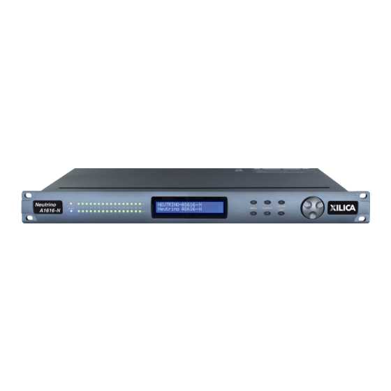
Front Panel Model Badge A badge displaying the device series and model name. Power A blue LED light which indicates that the hardware device is powered On. This LED light will flash when powering On the device or when performing a firmware upgrade. Network An orange LED light which indicates that a network cable is connected. - Page 5 Rear Panel 5 6* Power switch Power ON/OFF the processor using this switch. Power supply Insert the plug connector into the socket. Connect the cord into a 90- 240 VAC 50-60Hz power source. 3* AES/EBU Transport 8x8 AES/EBU digital audio channels over a DB-25 connector (Tascam protocol).
-
Page 6: Technical Specifications
Technical Specifications Input impedance >10k Ohms Output impedance 50 Ohms Maximum level +20dBu Mic/Line Mic (+40dB gain)/Line (0dB) Type Electronically balanced w/ 48V Phantom power Frequency response +/-0.15dB (20 to 20kHz) Dynamic range 110dB typ (unweighted) CMRR >50dB @ 1kHz Crosstalk <-110dB @1kHz Distortion... -
Page 7: Aes/Ebu Pinout Information
AES/EBU Pinout Information Neutrino-D models with AES/EBU digital audio use a DB-25 connector with the original TASCAM protocol. The pinout details are as follows: AES/EBU DB-25 to DB-25 connections require a different pinout in the cable. AES/EBU must ip the connections so that pins 12, 24 and 25 will wind up on the other end of the cable at pins 6, 18 and 19 respectively. -
Page 8: Device Connectivity
Device Connectivity Xilica processors and control devices run on a network based infrastructure and are set up and controlled by a host computer using the Xilica Designer software. What’s in the Box • Neutrino hardware device • 90-240 VAC 50-60Hz power cable • 3.5mm Phoenix/Euro type terminal block connectors What you need to Provide • Computer • Network interface (Router, PoE switch) A router is used for IP assignment and easy connectivity to computer and control devices. - Page 9 A) Connecting using a DHCP enabled router/server Note: DHCP enabled Router/switch gear should be turned on first, with all Ethernet cables connected to the hardware prior to Powering ON the hardware. This will allow for proper IP address distribution to the Hardware. First, Power ON the router/switch gear.
-
Page 10: Install Xilica Designer
Install Xilica Designer The Xilica Designer software provides optimum configuration of X2, Solaro and Neutrino Series processors and it also configures Xilica’s programmable remote controls, configures and manages any networked Dante device, and provides universal third-party device control integration. Mac OS X Installation System Requirements Mac OS X 10.8 or later... -
Page 11: Windows Installation
Windows Installation System Requirements Windows 7 or higher Processor 1GHz or higher 500MB of available space 1GB graphics card 4GB RAM Download the latest version of Xilica Designer from the Xilica website (www.xilica.com). Open the downloaded .zip file. Then open the XilicaDesigner.exe file. An installation window will appear. -
Page 12: Launch Xilica Designer
Launch Xilica Designer Locate the Xilica Designer application on your Desktop or Applications folder. Double click the application to launch the software. You can create a New Design Project, Open Design Project, Start Network View, or Start Dante View. Network View Network View displays all processors and control devices on the network. -
Page 13: Firmware Upgrade
At times you may just see an exclamation mark (!). This indicates that a firmware upgrade is available. Normally this is not an issue unless there are updated modules in the project file that the outdated firmware does not support. Firmware Upgrade Please note that using an older version of software with a newer firmware or newer software with an older firmware will work but some of the features may not be available and bugs could exist. - Page 14 Firmware Upgrade Procedure: Save any design files from the device onto your computer as all programmed data on the device will be erased during the upgrade process. After the firmware upgrade is completed, the design file can be loaded back into your device. The device must be online and operational (green ON indicator) to perform a firmware upgrade.
- Page 15 Navigate to the file in which you downloaded the new Firmware file. Click Open. A status bar in the device window will monitor the Firmware upgrade progress. Once the Firmware file has been loaded to the device, the device will automatically restart and update its internal data.
-
Page 16: Project View
Project View You can create a new project in one of two ways: Auto-configuration If your device is listed in network view, select your device and click Create New Project with Selected Device(s) at the top right of the software. This will create a project with your processor. Blank project Alternatively, click File >... -
Page 17: Create A Design
Create a Design For the example, a single DSP hardware block will be used, but a design can be done with multiple DSP hardware items. Projects can be designed Offline (no devices connected) and the design can be loaded to your devices at a later time. - Page 18 Double click the DSP module to open the design schematic. Resize the window by dragging the corner of the window. To space out your work area, click & drag a selection box around the output modules and use the cursor arrows or mouse to move the modules to the right. When this window is selected, the Component Library menu displays a variety of DSP modules.
- Page 19 Click and drag a DSP module into the device schematic window. In the example, a PEQ was added. In the Object Property menu, you can customize the module. For the PEQ module, up to 8 bands are available. Double click the DSP module to open it. In the PEQ module, the number of bands determined in the object property menu is reflected in the DSP module.
- Page 20 Drag & drop more DSP modules, then wire them accordingly. Processing chains and objects can be easily duplicated by selecting the desired object(s), Ctrl + C to copy, then Ctrl + V to paste the items. When drawing wires, they may overlap and be difficult to read. To move wires, click &...
- Page 21 To save your project, click File > Save As. Save the file to a memorable location. If a project file is already created, click File > Save. You can also save using the save icon at the top right of the work area. It is recommended to back up project files to an external location.
-
Page 22: Going Online
Going Online Going online loads the design file to the connected device(s) and allows you to make adjustments in real-time. In order to go online, all devices must be connected and online. (Green ON indicator in Network View) To go online, you must associate the device module with the physical hardware device. 1. - Page 23 Once mapped, the module will become a solid grey color and the device Mac Address will display at the bottom of the device module. Click Load Design to Device(s) located at the top of the work area. A window will pop up. Check the devices that you would like to load your design to. Then click OK.
-
Page 24: Going Online
Going online may take up to several minutes. Please do not disrupt the process. The progress bar at the top will display the overall progress percentage. Once online, notice that the work area has become a solid color and the design menus are no longer available. - Page 25 Double click any DSP module or I/O block to make adjustments. Switch back to design mode at any time using the Go Back to Design Mode button located at the top of the work area. You will be asked if you’d like to copy the adjustments made online, back into the project design. Click Yes to transfer the settings made online into the project.
-
Page 26: Contact And Support
Customer Support If you’d like to contact us regarding product support or technical designs, email support@xilica.com and we’ll connect you with a solutions engineer Alternatively, if you’d like to speak to someone, you can call the following numbers for immediate assistance: International: +1 905 770-0055 US Toll Free:...
Need help?
Do you have a question about the NEUTRINO series and is the answer not in the manual?
Questions and answers