Table of Contents
Troubleshooting

Subscribe to Our Youtube Channel
Related Manuals for Tech West ACL2S2


Summary of Contents for Tech West ACL2S2
- Page 1 ULTRA CLEAN LUBRICATED COMPRESSOR INSTALLATION AND SERVICE Manufacturers of Dental Vacuum MANUAL and Air Systems 2625 N. Argyle Ave. • Fresno, CA 93727 Revised 4-15 (559) 291-1650 • (800) 428-7139 • FAX (559) 348-9677...
-
Page 3: Table Of Contents
ULTRA CLEAN LUBRICATED COMPRESSOR INSTALLATION AND SERVICE MANUAL This manual is for the installation and service of Tech West’s Ultra Clean Lubricated Compressors. CONTENTS Installation Location Requirements Figure 1: Wire and Breaker Size Installation Steps Figure 2: Compressor Connections Start Up... - Page 4 Maintenance & Service / Notes...
-
Page 5: Installation
CAUTION - Voltage must be 208/240 v or motor damage may occur. Figure 1: Recommended Wire and Breaker Size Model Voltage Amperage Wire Size Recommended (Gauge) Breaker Size Single Head Compressors ACL2S2 ACL2S1 13.6 Dual Head Compressors ACL4D2 14.4 Triple Head Compressors ACL6T2 21.6... -
Page 6: Installation Steps
2. INSTALLATION STEPS This dental Compressor should only be installed by qualified personnel. Should any questions arise during the installation, call Tech West Technical Support between the hours of 7:00 a.m. to 4:00 p.m. (Pacific Standard Time). Place the compressor in a clean, dry, well ventilated area, on a solid, level surface. Consider sound level and insulate as needed. - Page 7 ULTRA CLEAN LUBRICATED COMPRESSOR INSTALLATION 3. CONNECTIONS Figure 2 Electrical Connection to disconnect and electrical panel 220 v (110 v / 220 v ) on the single models only. Dryer Purge Air Out Connection Connection to building supply line. Alternate Air Connection to fresh air supply.
-
Page 8: Start Up
5. PERIODIC SERVICING WEEKLY SERVICING (a) Check the oil level. Refer to figure 2. Use only Tech West oil specially formulated for Tech West Compressors. DO NOT OVERFILL. Add oil only when the oil level remains below the center line of the oil-level sight glass after the compressor has been idle for at least 5 minutes. - Page 9 Figure 3: Checking and Changing the Oil Instructions Add oil to compressor through oil filler spout. Do not overfill. Keep filled to level as shown below. Oil should be changed annually or when oil becomes discolored. Oil Filler Spout Check oil level with compressor off and compressor sitting level.
-
Page 10: Parts Breakdown
HEAD COVER AND FAN ASSEMBLY PART NO. DESCRIPTION UNIT CCH-115 115 V COPELAND COMPRESSOR HEAD 1HP CCH-230 230 V COPELAND COMPRESSOR HEAD 1 HP CF-115 115 V COOLING FAN CF-230 230 V COOLING FAN CFS-100 COMPRESSOR FAN SHROUD CFG-100 FINGER GUARD OSG-100 OIL SIGHT GLASS... - Page 11 Figure 4: AIR COMPRESSOR STARTER ASSEMBLY ULTRA CLEAN AIR COMPRESSOR STARTER ASSEMBLY PART NO. DESCRIPTION UNIT CRA-115 115 V CAP AND RELAY ASSEMBLY, COMPLETE CRA-208 208-230 V CAP AND RELAY ASSEMBLY, COMPLETE CRA-230 230 V ONLY CAP AND RELAY ASSEMBLY, COMPLETE PR-115 115 V POTENTIAL RELAY PR-208...
- Page 12 SINGLE COMPRESSOR CONFIGURATION DUAL AND TRIPLE COMPRESSOR CONFIGURATION GAUGE AND CUT-OFF ASSEMBLY PART NO. DESCRIPTION UNIT CPG-250 COMPRESSOR GAUGE BV-250 1/4” BALL VALVE MI-100 MOISTURE INDICATOR FA-4-4 1/4” FLARE HOSE FITTING BN-250-CL 1/4” BRASS CLOSE NIPPLE BT-250 1/4” BRASS TEE BSE-250 1/4”...
- Page 13 REAR VIEW ASSEMBLY AND PARTS LIST PART NO. DESCRIPTION UNIT CV-375MF-100 3/8 CHECK VALVE MALE TO FEMALE CONNECTION CPT-100 COMPRESSOR PURGE TANK CV-375D-100 3/8 CHECK VALVE HA-12-250 1/4 HOSE ASSEMBLY - 12” LONG DPC-1 DRYER PRE COOLER SINGLE COMPRESSOR DPC-2 DRYER PRE COOLER DUAL &...
-
Page 14: Dessicant Dryer Parts Breakdown
NEW DESICCANT AIR DRYER ASSEMBLY INSIDE TANK ELEMENT... -
Page 15: Coalescing Filter Parts Breakdown
FILTER ASSEMBLY PART NO. DESCRIPTION UNIT CFAO-375 COALESCING FILTER ASSEMBLY 3/8 CFEO-375 COALESCING FILTER ELEMENT 3/8 CFBP-375 COALESCING FILTER BOWL... -
Page 16: Single Ultra Clean Lubricated Compressor Assembly
SINGLE ULTRA CLEAN LUBRICATED COMPRESSOR PART NO. DESCRIPTION UNIT SBHA-21-375 STEEL BRAID HOSE ASSEMBLY SBHA-7.5-375E STEEL BRAID HOSE ASSEMBLY SBHA-21-375E STEEL BRAID HOSE ASSEMBLY FPH-375 PURGE FLEX HOSE CLEAR PER FT ZZACS61 1/4 HOSE ASSEMBLY PFT-500 POLY FLO TUBE 1/2 PER FT CFAO-375 COALESCING FILTER 3/8... -
Page 17: Dual Ultra Clean Lubricated Compressor Assembly
DUAL ULTRA CLEAN LUBRICATED COMPRESSOR PART NO. DESCRIPTION UNIT SBHA-21-375 STEEL BRAID HOSE ASSEMBLY SBHA-10-375E STEEL BRAID HOSE ASSEMBLY SBHA-9-375E STEEL BRAID HOSE ASSEMBLY FPH-375 PURGE FLEX HOSE CLEAR PER FT ZZACS61 1/4 HOSE ASSEMBLY PFT-500 POLY FLO TUBE 1/2 PER FT CFAO-375 COALESCING FILTER 3/8... -
Page 18: Triple Ultra Clean Lubricated Compressor Assembly
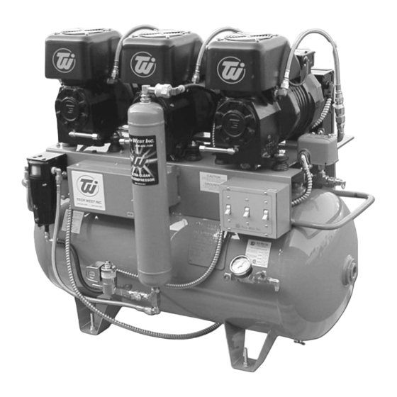
TRIPLE ULTRA CLEAN LUBRICATED COMPRESSOR PART NO. DESCRIPTION UNIT SBHA-21-375 STEEL BRAID HOSE ASSEMBLY SBHA-10-375E STEEL BRAID HOSE ASSEMBLY SBHA-9-375E STEEL BRAID HOSE ASSEMBLY FPH-375 PURGE FLEX HOSE CLEAR PER FT ZZACS61 POLY FLO TUBE 1/4 PFT-500 POLY FLO TUBE 1/2 PER FT CFAO-375 COALESCING FILTER 3/8... -
Page 19: Compressor Wiring Diagram
Figure 5: Compressor Wiring Diagram... -
Page 26: Air Line Sizing Chart
Maintenance & Service / Notes... - Page 27 Maintenance & Service / Notes...
- Page 28 Manufacturers of Dental Vacuum and Air Systems 2625 N. Argyle Ave. • Fresno, CA 93727 (559) 291-1650 • (800) 428-7139 • FAX (559) 348-9677...
Need help?
Do you have a question about the ACL2S2 and is the answer not in the manual?
Questions and answers