Table of Contents
Advertisement
Quick Links
Getting Started
Chapter 1
Getting Started
Thank you for choosing the MS-7521 v3.X Micro-ATX
mainboard. The MS-7521 v3.X Micro-ATX mainboard is
®
based on Intel
P43 & ICH10R chipsets for optimal sys-
®
tem efficiency. Designed to fit the advanced Intel
Core
2 Quad, Core 2 Duo, Pentium Dual-Core an d
Celeron Dual-Core LGA775 processor, the MS-7521
v3.X Micro-ATX mainboard delivers a high performance
and professional desktop platform solution.
1-1
Advertisement
Table of Contents

Related Manuals for MSI MS-7521


Summary of Contents for MSI MS-7521
- Page 1 Getting Started Chapter 1 Getting Started Thank you for choosing the MS-7521 v3.X Micro-ATX mainboard. The MS-7521 v3.X Micro-ATX mainboard is ® based on Intel P43 & ICH10R chipsets for optimal sys- ® tem efficiency. Designed to fit the advanced Intel...
-
Page 2: Mainboard Specifications
M S-7521 M ainboard Mainboard Specifications Processor Support ® - Intel Core 2 Quad, Core 2 Duo, Pentium Dual-Core and Celeron Dual-Core processors in the LGA775 package - Intel ® next generation 45 nm Multi-core CPU Supported FSB - 1333/ 1066/ 800 MHz Chipset - North Bridge: Intel ®... - Page 3 Getting Started On-Board Pinheaders / Connectors - 3 USB 2.0 pinheaders - 1 1394 pinheader - 1 front audio pinheader - 1 S/PDIF out pinheader Slots - 1 PCI Express x16 slot, supports up to PCI Express 2.0 x16 speed - 1 PCI Express x1 slot - 2 PCI slots, support 3.3V/ 5V PCI bus Interface Form Factor...
-
Page 4: Mainboard Layout
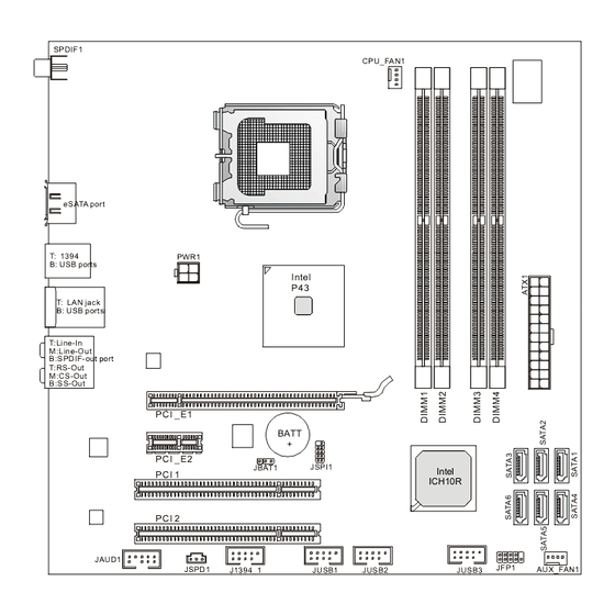
T: LAN jack B: USB ports T:Line-In M :Line-Out B:SPDIF- out port T:RS- Out M :CS-Out B:SS-Out PCI _E1 BATT PCI _E2 JSPI1 JBAT1 Intel PCI 1 ICH10R PCI 2 JAUD1 JFP1 JSPD1 AUX_FAN1 J1394_1 JUSB1 JUSB2 JUSB3 MS-7521 v3.X Micro-ATX Mainboard... -
Page 5: Hardware Setup
Hardware Setup Chapter 2 Hardware Setup This chapter provides you with the information about hardware setup procedures. While doing the installation, be careful in holding the components and follow the installation procedures. For some components, if you install in the wrong orientation, the components will not work properly. -
Page 6: Quick Components Guide
M S-7521 M ainboard Quick Components Guide CPU, p.2-3 PWR1, CPUFAN1, p.2-9 p.2-12 DDR2 DIMMs, p.2-7 Back Panel, p.2-10 ATX1, p.2-9 PCIE, p.2-17 JBAT1, SATA, p.2-16 p.2-12 PCI, p.2-17 JFP1, JAUD1, p.2-14 p.2-14 J1394_1, JUSB1~3, AUX_FAN1, JSPD1, p.2-13 p.2-15 p.2-13 p.2-12... -
Page 7: Introduction To Lga 775 Cpu
Hardware Setup CPU (Central Processing Unit) W hen you are installing the CPU, make sure to install the cooler to prevent overheating. If you do not have the CPU cooler, consult your dealer before turning on the computer. Important Overheating Overheating will seriously damage the CPU and system. -
Page 8: Cpu & Cooler Installation
M S-7521 M ainboard CPU & Cooler Installation W hen you are installing the CPU, make sure the CPU has a cooler attached on the top to prevent overheating. Meanwhile, do not forget to apply some thermal paste on CPU before installing the heat sink/cooler fan for better heat dispersion. Follow the steps below to install the CPU &... - Page 9 Hardware Setup 5. Lift the load lever up and open the 6. After confirming the CPU direction load plate. for correct mating, put down the CPU in the socket housing frame. Be sure to grasp on the edge of the CPU base. Note that the align- ment keys are matched.
- Page 10 M S-7521 M ainboard 9. Press down the load lever lightly 10. Align the holes on the mainboard onto the load plate, and then se- with the heatsink. Push down the cure the lever with the hook under c ooler u nti l i ts f ou r c lip s g et retention tab.
-
Page 11: Dual-Channel Memory Population Rules
Hardware Setup Memory These DIMM slots are used for installing memory modules. DDR2 240-pin, 1.8V 64x2=128 pin 56x2=112 pin Dual-Channel Memory Population Rules In Dual-Channel mode, the memory modules can transmit and receive data with two data bus lines simultaneously. Enabling Dual-Channel mode can enhance the system performance. -
Page 12: Installing Memory Modules
M S-7521 M ainboard Installing Memory Modules 1. The memory module has only one notch on the center and will only fit in the right orientation. 2. Insert the memory module vertically into the DIMM slot. Then push it in until the golden finger on the memory module is deeply inserted in the DIMM slot. -
Page 13: Power Supply
Hardware Setup Power Supply ATX 24-Pin Power Connector: ATX1 This connector allows you to connect an ATX 24-pin power supply. To connect the ATX 24-pin power supply, make sure the plug of the power supply is inserted in the proper orientation and the pins are aligned. Then push down the power supply firmly into the connector. -
Page 14: Back Panel
M S-7521 M ainboard Back Panel 1394 Port RS-Out Line-In CS-Out Line-Out E-SATA Port SS-Out S/PDIF-Out USB Ports (Coaxial) S/PDIF-Out (Coaxial) This SPDIF (Sony & Philips Digital Interconnect Format) connector is provided for digital audio transmission to external speakers through a coaxial cable. ESATA Port The External-SATA port is for attaching the ESATA external hard drive. - Page 15 Hardware Setup Audio Ports These audio connectors are used for audio devices. You can differentiate the color of the audio jacks for different audio sound effects. Line-In (Blue) - Line In is used for external CD player, tapeplayer or other audio devices. Line-Out (Green) - Line Out, is a connector for speakers or headphones.
- Page 16 M S-7521 M ainboard Connectors Serial ATA Connector: SATA1~6 This connector is a high-speed Serial ATA interface port. Each connector can connect to one Serial ATA device. SATA2 SATA3 SATA1 SATA6 SATA5 SATA4 Important Please do not fold the Serial ATA cable into 90-degree angle. Otherwise, data loss may occur during transmission.
- Page 17 Hardware Setup IEEE1394 Connector: J1394_1 This connector allows you to connect the IEEE1394 device via an optional IEEE1394 bracket. Pin Definition SIGNAL SIGNAL TPA+ TPA- Ground Ground TPB+ TPB- J1394_1 Cable power Cable power Key (no pin) Ground SPDIF-Out Connector: JSPD1 This connector is used to connect S/PDIF (Sony &...
-
Page 18: Front Panel Connectors: Jfp1
M S-7521 M ainboard Front Panel Connectors: JFP1 The connector is for electrical connection to the front panel switches and LEDs. The JFP1 is compliant with Intel ® Front Panel I/O Connectivity Design Guide. Power Power Switch JFP1 Reset Switch JFP1 Pin Definition SIGNAL DESCRIPTION... -
Page 19: Front Usb Connector: Jusb1
Hardware Setup Front USB Connector: JUSB1~3 These connectors, compliant with Intel ® I/O Connectivity Design Guide, is ideal for connecting high-speed USB interface peripherals such as USB HDD, digital cameras, M P3 players, printers, modems and the like. Pin Definition SIGNAL SIGNAL USB0-... - Page 20 M S-7521 M ainboard Jumper Clear CMOS Jumper: JBAT1 There is a CMOS RAM onboard that has a power supply from an external battery to keep the data of system configuration. W ith the CMOS RAM, the system can auto- matically boot OS every time it is turned on.
-
Page 21: Pci (Peripheral Component Interconnect) Express Slot
Hardware Setup Slots PCI (Peripheral Component Interconnect) Express Slot The PCI Express slot supports the PCI Express interface expansion card. The PCI Express x16 slot supports up to 8.0 GB/s transfer rate. The PCI Express x1 slot supports up to 250 MB/s transfer rate. PCI Express x16 Slot PCI Express x 1 Slot PCI (Peripheral Component Interconnect) Slot... -
Page 22: Bios Setup
BIOS Setup Chapter 3 BIOS Setup This chapter provides information on the BIOS Setup program and allows you to configure the system for optimum use. You may need to run the Setup program when: An error message appears on the screen during the system booting up, and requests you to run SETUP. -
Page 23: Entering Setup
M S-7521 M ainboard Entering Setup Power on the computer and the system will start POST (Power On Self Test) process. W hen the message below appears on the screen, press <DEL> key to enter Setup. Press DEL to enter SETUP If the message disappears before you respond and you still wish to enter Setup, restart the system by turning it OFF and On or pressing the RESET button. -
Page 24: Control Keys
BIOS Setup Control Keys < ↑> Move to the previous item < ↓> Move to the next item < ←> Move to the item in the left hand < →> Move to the item in the right hand <Enter> Select the item <Esc>... -
Page 25: The Main Menu
M S-7521 M ainboard The Main Menu Standard CM OS Features Use this menu for basic system configurations, such as time, date etc. Advanced BIOS Features ® Use this menu to setup the items of AMI special enhanced features. Integrated Peripherals Use this menu to specify your settings for integrated peripherals. - Page 26 BIOS Setup Save & Exit Setup Save changes to CMOS and exit setup. Exit Without Saving Abandon all changes and exit setup.
-
Page 27: Standard Cmos Features
M S-7521 M ainboard Standard CMOS Features The items in Standard CMOS Features Menu includes some basic setup items. Use the arrow keys to highlight the item and then use the <PgUp> or <PgDn> keys to select the value you want in each item. Date (MM:DD:YY) This allows you to set the system to the date that you want (usually the current date). - Page 28 BIOS Setup Device This item shows the device name that you connected to the E-SATA connector. LBA/Large M ode This allows you to enable or disable the LBA Mode. Setting to Auto enables LBA mode if the device supports it and the devices is not already formatted with LBA mode disabled.
-
Page 29: Advanced Bios Features
M S-7521 M ainboard Advanced BIOS Features BIOS Flash Protection W hen enabled, the BIOS’ data cannot be changed when attempting to update the BIOS with a Flash utility. To successfully update the BIOS, you’ll need to disable this Flash BIOS Protection function. You should enable this function at all times. The only time when you need to disable it is when you want to update the BIOS. - Page 30 BIOS Setup M PS Table Version This field allows you to select which MPS (Multi-Processor Specification) version to be used for the operating system. You need to select the MPS version supported by your operating system. To find out which version to use, consult the vendor of your operating system.
- Page 31 M S-7521 M ainboard Boot Sequence Press <Enter> to enter the sub-menu and the following screen appears: 1st/ 2nd/ 3rd Boot Device The items allow you to set the first/ second/ third boot device where BIOS attempts to load the disk operating system. Boot From Other Device Setting the option to [Yes] allows the system to try to boot from other device, if the system fails to boot from 1st/ 2nd boot device.
-
Page 32: Integrated Peripherals
BIOS Setup Integrated Peripherals USB Controller This setting allows you to enable/disable the onboard USB controller. USB Device Legacy Support Select [Enabled] if you need to use a USB-interfaced device in the operating system. Onboard LAN Controller This item is used to enable/disable the onboard 1st LAN controller . LAN Boot This item is used to decide whether to invoke the Boot ROM of the LAN controller. - Page 33 M S-7521 M ainboard On-Chip ATA Devices Press <Enter> to enter the sub-menu and the following screen appears: PCI IDE BusMaster This item allows you to enable/ disable BIOS to used PCI busmastering for reading/ writing to IDE drives. On-Chip SATA Controller These items allow users to enable or disable the SATA controller.
- Page 34 BIOS Setup Hard Disk S.M.A.R.T. This allows you to activate the S.M.A.R.T. (Self-Monitoring Analysis & Reporting Technology) capability for the hard disks. S.M.A.R.T is a utility that monitors your disk status to predict hard disk failure. This gives you an opportunity to move data from a hard disk that is going to fail to a safe place before the hard disk becomes offline.
-
Page 35: Power Management Setup
M S-7521 M ainboard Power Management Setup Important S3-related functions described in this section are available only when your BIOS supports S3 sleep mode. ACPI Function This item is to activate the ACPI (Advanced Configuration and Power Management Interface) Function. If your operating system is ACPI-aware, such as W indows 2000/ XP, select [Enabled]. - Page 36 BIOS Setup Soft off by PWR BTTN This feature allows users to configure the power button function. Settings are: [Instant-Off] The power button functions as a normal power-on/- off button. [By HardW are] W hen you press the power button, the computer enters the suspend/sleep mode, but if the button is pressed for more than four seconds, the computer is turned off.
- Page 37 M S-7521 M ainboard H/W Monitor System Smart FAN Target The mainboard provides the Smart Fan function which can control the System fan speed automatically depending on the current temperature to keep it with in a specific range. You can enable a fan target value here. If the current system fan temperature reaches to the target value, the smart fan function will be activated.
-
Page 38: Security Settings
BIOS Setup Security Settings Security Settings The field shows the Supervisor and User Password status, read to know whether the password is set or not (read only). Set Supervisor Password Press <Enter> to set the Supervisor Password. Once the superivor password is set, you will see below items available to adjust: User Access Level, Set User Password, Clear User Password, and Password Check. -
Page 39: Frequency/Voltage Control
M S-7521 M ainboard Frequency/ Voltage Control Important Change these settings only if you are familiar with the chipset. Current CPU / DRAM Frequency These items show the current clocks of CPU and Memory speed. Read-only. Intel EIST The Enhanced Intel SpeedStep technology allows you to set the performance level of the microprocessor whether the computer is running on battery or AC power. - Page 40 BIOS Setup MEMORY-Z Press <Enter> to enter the sub-menu and the following screen appears. DIMM 3 Memory SPD Information Press <Enter> to enter the sub-menu and the following screen appears. The screen shows the type, bandwidth, manufacture and other information of the DIMM3 Memory.
-
Page 41: Load Fail-Safe/ Optimized Defaults
M S-7521 M ainboard Load Fail-Safe/ Optimized Defaults The two options on the main menu allow users to restore all of the BIOS settings to the default Fail-Safe or Optimized values. The Optimized Defaults are the default values set by the mainboard manufacturer specifically for optimal performance of the mainboard.
Need help?
Do you have a question about the MS-7521 and is the answer not in the manual?
Questions and answers