Table of Contents
Advertisement
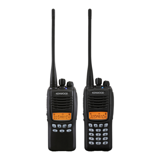
VHF FM TRANSCEIVER
TK-2317
SERVICE MANUAL
M3 version
Helical antenna
(T90-1050-05)
Button knob (PTT)
(K29-9425-03)
Button knob
(SIDE1/SIDE2)
(K29-9426-03)
Key top (7key)
(K29-9463-12)
Plastic cabinet assy
(A02-4095-23)
RoHS
This product complies with the
Knob (Selector)
(K29-9427-03)
Knob (Volume)
(K29-9309-13)
directive for the European market
© 2011-4 PRINTED IN JA PAN
B51-8972-00 ( Y ) PDF
CONTENTS
GENERAL ....................................................2
SYSTEM SET-UP .........................................3
REALIGNMENT ...........................................3
DISASSEMBLY FOR REPAIR .....................9
CIRCUIT DESCRIPTION ...........................12
SEMICONDUCTOR DATA .........................17
COMPONENTS DESCRIPTION ................18
PARTS LIST ...............................................19
EXPLODED VIEW ......................................27
PACKING ...................................................28
ADJUSTMENT ...........................................29
TX-RX UNIT (X57-7880-21) ....................34
SCHEMATIC DIAGRAM ............................38
BLOCK DIAGRAM .....................................44
LEVEL DIAGRAM ......................................46
KNB-29N (Ni-MH Battery Pack) ............47
KNB-45L (Li-ion Battery Pack) .............47
KNB-53N (Ni-MH Battery Pack) ............47
SPECIFICATIONS .................. BACK COVER
.
This product uses Lead Free solder
.
Advertisement
Table of Contents

Related Manuals for Kenwood TK-2317 M3


Summary of Contents for Kenwood TK-2317 M3
-
Page 1: Table Of Contents
VHF FM TRANSCEIVER TK-2317 SERVICE MANUAL M3 version © 2011-4 PRINTED IN JA PAN B51-8972-00 ( Y ) PDF CONTENTS GENERAL ............2 SYSTEM SET-UP .........3 REALIGNMENT ...........3 DISASSEMBLY FOR REPAIR .....9 CIRCUIT DESCRIPTION ......12 SEMICONDUCTOR DATA ......17 Helical antenna Knob (Selector) (T90-1050-05) (K29-9427-03) COMPONENTS DESCRIPTION ....18... -
Page 2: General
Kenwood assumes no responsibility for errors or omissions. Neither is any liability assumed for damages resulting from the use of the information contained herein. Kenwood reserves the right to make changes to any products herein at any time for improvement purposes. GENERAL... -
Page 3: System Set-Up
RF power Type Choose the type of transceiver TX/RX 216~223 5.0W TK-2317 M3 A personal computer, programming interface (KPG-22A/22U), Transceiver programming and FPU (programming software) are required for programming. (The frequency, TX power HI/LOW, and signaling data are programmed for the transceiver.) - Page 4 TK-2317 REALIGNMENT When using the KCT-53U, install the supplied CD-ROM 3. PC Mode (with driver software) in the computer. The KCT-53U driver 3-1. Preface runs under Windows 2000, XP or Vista (32-bit). The transceiver is programmed by using a personal com- puter, a programming interface (KPG-22A/22U, USB adapter 3-6.
- Page 5 TK-2317 REALIGNMENT • Electronic interface may cause a failure in data transfer 4. Wireless Clone Mode during Wireless Clone, such as when waveforms or elec- 4-1. Outline tromagnetics are being performed at the workbench. “Wireless Clone Mode” copies the transceiver data to an- •...
-
Page 6: Self Programming Mode
TK-2317 REALIGNMENT Key operation 5. Self Programming Mode Key Function Write mode for frequency data and signaling, etc. To be used ONLY by the authorized service person maintaining the Toggle between Zone selection and Channel selec- [Selector] tion user's equipment. After programming, reset the FPU to the “Self- Programming”... - Page 7 TK-2317 REALIGNMENT 5-5. Item Setting Mode 5-6. Self Programming Mode fl ow chart ■ Channel selection mode fl ow chart In this mode, the selected item in the Item Selection mode can be programmed. When the [S] key is pressed in the Item Selection mode, [S]+Power ON Display the transceiver enters the Item Setting mode.
- Page 8 TK-2317 REALIGNMENT ■ Item setting mode fl ow chart 6. Firmware Version Information Mode Display Turn the transceiver ON with the [Side1] and [Side2] keys Current 216. 00000 held down. Then, the version is displayed during holding the setting value [1.
-
Page 9: Disassembly For Repair
TK-2317 DISASSEMBLY FOR REPAIR 1. Removing the Case Assembly from the 3. Removing the TX-RX unit from the Chassis Chassis 1. Remove the selector knob a and volume knob b . 1. Remove the eleven screws f fi xing the TX-RX unit. 2. - Page 10 TK-2317 DISASSEMBLY FOR REPAIR 5. Attaching the Battery Release Lever to 6. Assembling the Battery Release Lever 1. Place the lever b onto the stopper a . the Case Assembly 2. Place the thick spring c onto the lever. 1. Insert one side of the shaft into the hole at the lever fi tting 3.
- Page 11 TK-2317 DISASSEMBLY FOR REPAIR 8. Mounting the Chassis to the Case 10. The Nuts of the Volume Knob and Assembly Channel Knob 1. Confirm that the waterproof packing attached to the Note that the shapes, colors and heights of nuts of the circumference of the chassis is securely inserted in the volume knob and channel knob are different from one groove of the chassis a .
-
Page 12: Circuit Description
TK-2317 CIRCUIT DESCRIPTION 1. Frequency Confi guration The receiver utilizes double conversion. The first IF is 49.95MHz and the second IF is 450kHz. The fi rst Local os- cillator is supplied from the PLL circuit. The PLL circuit in the transmitter generates the neces- sary frequencies. - Page 13 TK-2317 CIRCUIT DESCRIPTION 2-3. IF Amplifi er Circuit 2-5. Audio Amplifi er Circuit The fi rst IF signal is passed through a four-pole mono- The demodulated signal from IC401 is sent to an AF am- lithic crystal fi lter (XF401) to remove the adjacent channel plifi...
- Page 14 TK-2317 CIRCUIT DESCRIPTION 3-2. Drive and Final Amplifi er Circuit 3-3. APC Circuit The signal from the T/R switch (D18 is on) is amplifi ed by The APC circuit always monitors the current flowing the RF AMP (Q201) and pre-drive amplifi er (Q203) to 50mW. through the drive amplifi...
- Page 15 TK-2317 CIRCUIT DESCRIPTION 5-2. Memory Circuit The Memory circuit consists of the MCU (IC820) and EEPROM (IC810). The EEPROM has a capacity of 512k bits TX/RX BUFF BUFF (TX: High) RF AMP and stores the channel information, the last channel data, the scan on status, and other parameters.
- Page 16 TK-2317 CIRCUIT DESCRIPTION ■ High-speed data (2-tone) 5-4. Key Input Keys and channel selector circuit. High-speed data (HSD) is output from pin 3 of the MCU. The signal from the keys and channel selector are direct- HSD deviation made by an adjustment in the MCU is passed ly input to the MCU, as shown in Figure 10.
-
Page 17: Semiconductor Data
TK-2317 SEMICONDUCTOR DATA MCU: F363BEDFEKDLC (TX-RX unit IC820) Pin No. Signal Name Function CM_DTI Baseband IC data input Pin No. Signal Name Function CM_CNS Baseband IC chip select output BSHIFT CPU clock frequency shift DC_SW APC voltage discharge switch LSDO QT/DQT output KEY1O Key matrix output 1... -
Page 18: Components Description
TK-2317 COMPONENTS DESCRIPTION TX-RX unit (X57-7880-21) Ref. No. Use / Function Operation / Condition Q804 DC switching 33MS from 33M Ref. No. Use / Function Operation / Condition Q805 DC switching Green/Red LED PLL IC TX/RX 1st local Q806 DC switching MCU clock shift circuit OP amplifi... -
Page 19: Parts List
TK-2317 PARTS LIST 2 2 0 CC45 Color* 010 = 1pF 0 = 22pF 1 = Type ... ceramic, electrolytic, etc. 4 = Voltage rating 100 = 10pF 2 = Shape ... round, square, etc. 5 = Value 101 = 100pF Multiplier 3 = Temp. - Page 20 TK-2317 PARTS LIST ✽ New Parts. indicates safety critical components. L : Scandinavia L : Scandinavia K : USA K : USA P : Canada P : Canada Parts without Parts No. are not supplied. Y : PX (Far East, Hawaii) Y : PX (Far East, Hawaii) T : England T : England...
- Page 21 TK-2317 PARTS LIST TX-RX UNIT (X57-7880-21) Desti- Desti- Ref. No. Ad dress Parts No. Description Ref. No. Ad dress Parts No. Description parts nation parts nation C37 ,38 CK73HB1A104K CHIP C 0.10UF C244 CK73HB1H471K CHIP C 470PF CK73HB1H471K CHIP C 470PF C245 CC73HCH1H150J...
- Page 22 TK-2317 PARTS LIST TX-RX UNIT (X57-7880-21) Desti- Desti- Ref. No. Ad dress Parts No. Description Ref. No. Ad dress Parts No. Description parts nation parts nation C447 CC73HCH1H2R5B CHIP C 2.5PF C863 CK73HB1E103K CHIP C 0.010UF K C448 CC73HCH1H050B CHIP C 5.0PF C865 CK73HB1H471K...
- Page 23 TK-2317 PARTS LIST TX-RX UNIT (X57-7880-21) Desti- Desti- Ref. No. Ad dress Parts No. Description Ref. No. Ad dress Parts No. Description parts nation parts nation ✽ G11-4525-14 SHEET(LCD) L802,803 L92-0161-05 BEADS CORE L77-3050-05 TCXO(16.8MHZ) J21-8619-03 MOUNTING HARDWARE(LCD) X802 L78-1434-05 RESONATOR(19.2MHZ) XF401 L71-0655-05...
- Page 24 TK-2317 PARTS LIST TX-RX UNIT (X57-7880-21) Desti- Desti- Ref. No. Ad dress Parts No. Description Ref. No. Ad dress Parts No. Description parts nation parts nation RK73HB1J683J CHIP R 1/16W R416 RK73HB1J122J CHIP R 1.2K 1/16W RK73HB1J102J CHIP R 1.0K 1/16W R417 RK73HB1J154J...
- Page 25 TK-2317 PARTS LIST TX-RX UNIT (X57-7880-21) Desti- Desti- Ref. No. Ad dress Parts No. Description Ref. No. Ad dress Parts No. Description parts nation parts nation R844 RK73HB1J000J CHIP R 1/16W R926 RK73HB1J274J CHIP R 270K J 1/16W R845 RK73HB1J103J CHIP R 1/16W R927...
- Page 26 TK-2317 PARTS LIST TX-RX UNIT (X57-7880-21) Desti- Desti- Ref. No. Ad dress Parts No. Description Ref. No. Ad dress Parts No. Description parts nation parts nation IC802 XC6209B502M-G MOS-IC IC803 XC6209B502P-G MOS-IC IC804 XC6209B332M-G MOS-IC IC805 XC61CN4502M-G MOS-IC IC806 XC6209B332M-G MOS-IC IC807 XC6120N302N-G...
-
Page 27: Exploded View
TK-2317 EXPLODED VIEW TX-RX unit A : N14-0848-05 B : N14-0849-05 C : N30-2604-48 D : N30-2606-48 E : N83-2005-48 Parts with the exploded numbers larger than 700 are not supplied. -
Page 28: Packing
TK-2317 PACKING 7 Instruction manual (B62-2263-00) 66 Charger 704 Protection bag 73 Battery assy 48 Holder (SP/MIC) 50 Belt clip 60 Screw set 3 Cap 63 Helical antenna 705 Packing fixture 706 Item carton case Parts with the exploded numbers larger than 700 are not supplied. -
Page 29: Adjustment
TK-2317 ADJUSTMENT Test Equipment Required for Alignment Test Equipment Major Specifi cations Frequency Range 216 to 223MHz Standard Signal Generator (SSG) Modulation Frequency modulation and external modulation Output –127dBm/0.1µV to greater than –47dBm/1mV Input Impedance 50 RF Power Meter Operation Frequency 216 to 223MHz Measurement Range Vicinity of 10W... - Page 30 TK-2317 ADJUSTMENT Frequency and Signaling Preparations for Tuning the Transceiver The transceiver has been adjusted for the frequencies Before attempting to tune the transceiver, connect the shown in the following table. When required, re-adjust them unit to a suitable power supply. following the adjustment procedure to obtain the frequencies Whenever the transmitter is tuned, the unit must be con- you want in actual operation.
- Page 31 TK-2317 ADJUSTMENT Common Section Measurement Adjustment Item Condition Specifi cations / Remarks Test- Unit Terminal Unit Parts Method equipment 1. Setting 1) BATT terminal votage: 7.5V 2) SSG standard modulation [Wide] MOD: 1kHz, DEV: 3kHz [Narrow] MOD: 1kHz, DEV: 1.5kHz 2.
- Page 32 TK-2317 ADJUSTMENT Measurement Adjustment Item Condition Specifi cations / Remarks Test- Unit Terminal Unit Parts Method equipment 6. DQT 1) TEST CH: 1 Power 0.75kHz ±40Hz Deviation Deviation meter fi lter meter [Wide] LPF: 3kHz Deviation HPF: OFF meter PTT: ON Oscilloscope 7.
- Page 33 TK-2317 ADJUSTMENT Measurement Adjustment Item Condition Specifi cations / Remarks Test- Unit Terminal Unit Parts Method equipment 2. Open 1) TEST CH: Center, High Press [Start] Squelch (2 points) (Auto tuning) (5) [Wide] SSG otuput: –120dBm Oscilloscope (0.22µV) SSG MOD: 3.0kHz 2) TEST CH: Low (1 point) SSG otuput: –120dBm (0.22µV)
-
Page 34: Pc Board
TK-2317 PC BOARD TX-RX UNIT (X57-7880-21) Component side view (J79-0287-29) J79-0287-29 D819 C496 R469 R470 COM1 BPF1 COM2 COM3 COM4 SEG1 C811 SEG2 SEG3 SEG4 SEG5 R956 SEG6 D831 SEG7 R707 BATT SEG8 R703 SEG9 D830 SEG10 SEG11 BPF2 R701 SEG12 SEG13 CP840... - Page 35 TK-2317 PC BOARD TX-RX UNIT (X57-7880-21) Component side view (J79-0287-29) C819 R955 R312 C307 R306 R311 D819 C945 D824 D818 L302 Q304 IC301 Q305 CP836 C311 R318 IC810 R308 Q822 R235 C831 CP837 CN801 C861 C849 R852 C843 R839 R845 R824 CP840 C965...
- Page 36 TK-2317 PC BOARD TX-RX UNIT (X57-7880-21) Foil side view (J79-0287-29) SIDE2 SIDE1 C256 C818 R305 D301 Q301 L221 R456 C474 C495 L418 Q407 C302 C469 C250 R458 D408 R462 C486 C462 R209 L217 R213 C484 C482 R463 C209 L420 C205 L419 R215 C201...
- Page 37 TK-2317 PC BOARD TX-RX UNIT (X57-7880-21) Foil side view (J79-0287-29) J79-0287-29 SIDE2 R406 C406 C403 L410 L408 C402 D803 C455 C452 R409 R408 C447 C444 R450 R471 R445 R440 D402 C456 C464 R443 CF402 C463 C450 Q401 R444 C414 C466 R439 Q404 R844...
-
Page 38: Schematic Diagram
TK-2317 SCHEMATIC DIAGRAM TX-RX UNIT (X57-7880-21) SI GN BUSY B30-2314-05 B30-2315-05 B30-1790-05 D 8 0 1 D 8 0 4 D 8 0 5 DC SW BLUE LED 2 S K 1 8 3 0 F D C S W ON:3.3V Q 8 0 5 DC S W... - Page 39 TK-2317 SCHEMATIC DIAGRAM TX-RX UNIT (X57-7880-21) TH_DET THDET THDET AFCONT AFCONT CVIN CVIN BATT 3.3V 3.3V E E P RO M I C 8 1 0 CM_CSN CM_DTI V C C H o L D LCDBL R 9 7 8 HSDEC V S S R 9 6 8...
- Page 40 TK-2317 SCHEMATIC DIAGRAM TX-RX UNIT (X57-7880-21) THDET THDET AFCONT CVIN BATT C P 1 100x4 5.0V 5.0V R 1 6 PL_STB PL_DAT LOIN PL_CLK PL_UL CVIN DC AMP I C 2 TC X O 3.3V 7 LD B D 7 5 4 2 F V M CPVSS 8 PDN2 o U T 1...
- Page 41 TK-2317 SCHEMATIC DIAGRAM TX-RX UNIT (X57-7880-21) THDET 3.7V 1 5 n C 2 0 C 2 9 C 3 4 R 6 2 LOIN 2.5V 4 7 p 4 7 0 p C 7 2 C 7 3 2 S C 5 6 3 6 2.2V 3.9V C 8 5...
- Page 42 TK-2317 SCHEMATIC DIAGRAM TX-RX UNIT (X57-7880-21) THDET R 2 1 1 R 2 1 3 D R I V E R 2 0 3 R 2 0 6 R: 0V 1 . 0 k C 2 2 2 R D 0 1 M U S 1 - T 1 1 3 DRVOUT T:1.5V 1 .
- Page 43 TK-2317 SCHEMATIC DIAGRAM TX-RX UNIT (X57-7880-21) THDET F I N A L DRVOUT A N T S W R D 0 7 M U S 2 B T 1 1 2 A N T L 2 2 1 STRIP LINE L 2 1 2 L 2 1 3 L 2 1 4...
-
Page 44: Block Diagram
TK-2317 BLOCK DIAGRAM X57-7880-21 B30-2337-05 D818-D821,824 2SC5636 RF BUFFER LCD BACK LIGHT PL_STB Q820 2SC4617(S) PL_DAT 33MS Q821 2SB1694 D817 MA2S111-F PL_CLK MCH3914(7)-H LCDBL LCD DRIVER SWIN D4,D6,D8,D9 HVC375B-E PL_UL AK1541 D16 HVC350B LCDAT LCLD RF B LCCLK MOD2 IC821 NJU6434 33MS TXAST... - Page 45 TK-2317 BLOCK DIAGRAM VHF: 216MHz~ 223MHz VHF: 265.95MHz~272.95MHz (RX) 216MHz~223MHz (TX) D17,D18 Q201 Q203 Q204 Q205 D201,D202 HVC131 2SC5636 2SC5636 HSC277 2SC5636 2SC5455-A RD01MUS1-T113 RD07MUS2BT112 D203,D204 RN142S RF BUFFER TX/RX RF AMP RF AMP PRE DRIVE DRIVE AMP FINAL AMP ANT SW RF SW Q306...
-
Page 46: Level Diagram
TK-2317 LEVEL DIAGRAM... -
Page 47: Optional Accessories
TK-2317 OPTIONAL ACCESSORIES KNB-29N (Ni-MH Battery Pack) KNB-53N (Ni-MH Battery Pack) ■ External View ■ External View ■ Specifi cations ■ Specifi cations Voltage ............7.2V (1.2V x 6) Voltage ............7.2V (1.2V x 6) Battery capacity ............1500mAh Battery capacity ............1400mAh KNB-45L (Li-ion Battery Pack) KMC-48GPS (GPS Speaker Microphone) ■... -
Page 48: Specifications
Modulation Distortion ..........Less than 5% Measurements made per TIA/EIA-603 and specifi cations shown are typical. Kenwood reserves the right to change specifi cations without prior notice or obligation. 2967-3, Ishikawa-machi, Hachioji-shi, Tokyo, 192-8525 Japan P.O. BOX 22745, 2201 East Dominguez Street, Long Beach, Amsterdamseweg 37, 1422 AC Uithoorn, The Netherlands CA 90801-5745, U.S.A. - Page 49 TK-2317 TK-2317 PC BOARD PC BOARD TX-RX UNIT (X57-7880-21) Component side view (J79-0287-29) TX-RX UNIT (X57-7880-21) Component side view (J79-0287-29) C819 J79-0287-29 R955 R312 C307 R306 R311 D819 C945 D824 D818 C496 L302 R469 Q304 IC301 R470 COM1 BPF1 Q305 COM2 CP836 C311...
- Page 50 TK-2317 TK-2317 PC BOARD PC BOARD TX-RX UNIT (X57-7880-21) Foil side view (J79-0287-29) TX-RX UNIT (X57-7880-21) Foil side view (J79-0287-29) J79-0287-29 SIDE2 SIDE1 R406 C406 C256 C818 R305 C403 D301 L410 L408 C402 C455 C452 R409 R408 D803 C447 C444 R450 R471 Q301...
- Page 51 TX-RX UNIT (X57-7880-21) BUSY S I GN B30-2314-05 TH_DET THDET THDET THDET THDET THDET R 2 1 1 R 2 1 3 DRIVE THDET THDET AFCONT AFCONT AFCONT FINAL B30-2315-05 B30-1790-05 CVIN CVIN CVIN R 2 0 3 R 2 0 6 R: 0V 1 .
- Page 52 X57-7880-21 B30-2337-05 D818-D821,824 2SC5636 VHF: RF BUFFER 216MHz~ LCD BACK LIGHT 223MHz PL_STB Q820 2SC4617(S) PL_DAT VHF: 33MS 265.95MHz~272.95MHz (RX) Q821 2SB1694 216MHz~223MHz (TX) D817 MA2S111-F PL_CLK LCDBL MCH3914(7)-H LCD DRIVER SWIN D4,D6,D8,D9 HVC375B-E D17,D18 Q201 Q203 Q204 Q205 D201,D202 HVC131 PL_UL AK1541 D16 HVC350B...
Need help?
Do you have a question about the TK-2317 M3 and is the answer not in the manual?
Questions and answers