
Related Manuals for Eurotek EK-MFR/1

Summary of Contents for Eurotek EK-MFR/1
- Page 1 EK-MFR/1 Arch.2573 Sh. 1 of 35 Rev. E of 22/06/2007 501-000658/MN User’s handbook Digital radio Link EK-MFR/1 Eurotek s.r.l.
- Page 2 The test results show compliance with the Class A limits for radiated emissions. The present design is property of Eurotek s.r.l. and is protected by Copyright. Its reproduction, distribution and disclosure to third-parties without written authorisation is forbidden Every reproduction, re-distribution or disclosure without prior written authorisation is expressly forbidden by the law and can lead to serious civil and penal sanctions.
- Page 3 Eurotek not assumed responsibility for waste disposal in contrast with enforced laws. LIFE SUPPORT APPLICATIONS. Eurotek’s products are not designed for use as critical components in life support devices or system without the express written approval of the Eurotek S.r.l. As used herein.
- Page 4 EK-MFR/1 Arch.2573 Sh. 4 of 35 Rev. E of 22/06/2007 501-000658/MN First aid: artificial breathing(mouth to mouth) In case of electric shock you have to ensure the first aids to the patient, but to do this you have to consider two very important things: - interrupt immediately the electric circuit;...
-
Page 5: Table Of Contents
EK-MFR/1 Arch.2573 Sh. 5 of 35 Rev. E of 22/06/2007 501-000658/MN INDEX GENERAL DESCRIPTION ..................... 6 EK-MFR/1 ....................7 BLOCK SCHEME FRONT PANEL ......................... 8 ....................... 8 RONT PANEL VIEW ....................8 RONT PANEL DESCRIPTION REAR PANEL ..........................9 ......................... 9 EAR PANEL VIEW ..................... -
Page 6: General Description
Thanks to this function the user will be able to examine a log file stored inside the EK-MFR/1 and verify the type of alarm, the time and date in which the alarm occurred as well as the time and date in which the alarm stopped. The setting operation of every single board can be done locally on the keyboard, or by remote sites thanks to the placement of Ethernet 10/100 Base T interface located in the power supply section (EK-PWS/X ). -
Page 7: Ek-Mfr/1 Block Scheme
EK-MFR/1 Arch.2573 Sh. 7 of 35 Rev. E of 22/06/2007 501-000658/MN EK-MFR/1 block scheme Eurotek s.r.l. -
Page 8: Front Panel
EK-MFR/1 Arch.2573 Sh. 8 of 35 Rev. E of 22/06/2007 501-000658/MN FRONT PANEL Front panel view Front panel description General switch. Display. (chapter 4, Display and Keyboard) Keyboard. (chapter 4, Display and Keyboard) Enter key. Green LED (ON), for power on indication. -
Page 9: Rear Panel
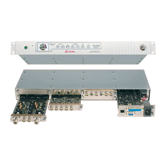
EK-MFR/1 Arch.2573 Sh. 9 of 35 Rev. E of 22/06/2007 501-000658/MN REAR PANEL Rear panel view Rear panel description Slot 0. Slot 1. Slot 2. EK-PWS/X* panel. Slot 5. Slot 4 < here it is possible to install the modem (EK-UNM/1). -
Page 10: Display And Keyboard
When the general switch (par. 2.2, front panel description) is turned on, the booting of the system is running. At the end of the booting the EK-MFR/1 is in stand-by modality (the display shows a black view) and after the user has pushed any of the keys, the display shows, the following configuration: Pressing the “enter”... - Page 11 Using the “explorer menu” keys (par. 2.2, front panel description), it is possible to see, on the display, the boards that the EK-MFR/1 contains and the relative slot associated to the board. The example below shows the EK-UNM/1 board that is inserted in the slot number 4. Pushing the “enter”...
-
Page 12: Display Mode
Sh. 12 of 35 Rev. E of 22/06/2007 501-000658/MN If any of the boards is not inserted in a particular slot of the EK-MFR/1, the display shows the following situation: Display mode A possible video signal of the inserted boards, are visible on the display that moreover supplies the output interface of the EK-MFR/1 processor. -
Page 13: Board Menu
EK-MFR/1 Arch.2573 Sh. 13 of 35 Rev. E of 22/06/2007 501-000658/MN BOARD MENU Menu representation The complete EK-MFR/1 menu is described below. Variable name Variable number MAIN-EK-MFR/1 > Passwords >> r/o PWD >> r/w PWD > Power Loops >> Loop 1 >>>... -
Page 14: Menu Description And Keyboard Guide
The Passwords menu allows to modify the reading only and the reading/writing password. To do this, the user must digit the password provided by the Eurotek, when the general switch (par. 2.2, front panel description) is turned on and the booting of the system is complete (par 4.1 display and keyboard description). - Page 15 The Power Loops menu allows to control automatically the output level of one board inserted in a slot in according to the output level of a board inserted in another slot of the EK-MFR/1. This functionality it used in order to keep constant the output power of a transmitter to adjusting the modulator output power.
- Page 16 3. >>>P Goal1 = -4db : indicates the back-off level to be obtained 4. >>>Enable1 = yes : the loop 1 function is enabled Now an independent program of EK-MFR/1 will try to keep the power of the transmitter (EK- CDP/1) constant in according to the power of the modulator (EK-UNM/1).
- Page 17 501-000658/MN >Save Config EK-MFR/1 allows to store four configurations system. To save a personal configuration, it is necessary to enter in the Save Config menu; it is possible to choose on which configuration to store the personal system settings pressing the “enter” key and using the “modifying variable” keys (par.
- Page 18 The Network menu allows to set, using the “modifying variable” keys, the following network configuration parameters, for the system: >> IP address >> IP netmask >> GW address. When the network configuration are changed by the user, the EK-MFR/1 must be rebooted. Eurotek s.r.l.
-
Page 19: Temperature Control
LEDs description • On (green light) : indicates that the EK-MFR/1 is active. The light is always on also if the display and the keys are off (if the user has to set the time to exit in the Miscellaneous menu of the EK-MFR/1). -
Page 20: About Operating System
ABOUT OPERATING SYSTEM Operating system connection. It is possible to connect the EK-MFR/1 with a terminal unit to use the RS232 interface (to see the rs232 interface settings in the Appendix C) or the Ethernet 10/100 Base T interface. The connectors, of these interfaces, are visible in the chapter 3 “rear panel”. -
Page 21: Erase_Log
EK-MFR/1 Arch.2573 Sh. 21 of 35 Rev. E of 22/06/2007 501-000658/MN M25P80 1024KB SPI flash found Go to last event ... Thu Apr 27 12:32:28 2005 [000166]: Slot 4 IF Rx Lev -18.3 Thu Apr 27 12:32:28 2005 [000165]: Slot 4 IF Tx Lev -12.2... -
Page 22: Exit
The SNMP commands are based on the SNMP protocol. To execute these commands is not necessary to enter in the system with a special login, the EK-MFR/1 must be connected with a terminal unit by the Ethernet 10/100 Base T interface only. The SNMP commands allow to obtain a complete view of the variable of the entire system so in every user’s handbook board, in the board... -
Page 23: Snmpwalk
The snmpwalk command allows to obtain the text file of the entire boards system or the text file of a single board inserted in the EK-MFR/1 unit. It is possible to obtain also the EK-MFR/1 text file. To launch the command, it is necessary to insert the next string: snmpwalk -v1 -c public 192.168.1.7 1.3.6.1.4.1.19222.1.(slot+2) -
Page 24: Snmpset
SNMPv2-SMI::enterprises.19222.1.1.3 = STRING: " 7" This message line indicates that the variable number 3 of the EK-MFR/1 (slot+2=1) is set to the 7 value. In the snmpset command, the option –r1 is available. This parameter is used in the unidirectional PPP protocol. -
Page 25: Snmpget
The web pages allows to read and modify the variables of every slot inserted in the EK-MFR/1 unit. To do this, it is necessary to connect the EK-MFR/1 with a terminal unit (PC), by the Ethernet 10/100 Base T interface. - Page 26 : super_user The password value is : pollon. When the user name and the password values are inserted, pushing on the OK window it is possible to enter in the EK-MFR/1 main web page like the next image shows: Eurotek s.r.l.
- Page 27 Rev. E of 22/06/2007 501-000658/MN The web page reported above, is the main page of the EK-MFR/1. The figure shows, in the down section, the rear panel of the unit (rear panel description paragraph) with the board that are inserted in the system.
-
Page 28: Ek-Mfr/1 Web
Password menu is active and the read only and read write password value are reported on the screen. In the top section of the page is reported the name of the selected unit (in this case EK-MFR/1) under the software tool name. - Page 29 The next example explains how to set a parameter of the EK-MFR/1 menu. We suppose to change the value of the time to exit parameter for the system; the procedure to set this variable is similar for the other parameter of the EK-MFR/1 unit.
- Page 30 EK-MFR/1 Arch.2573 Sh. 30 of 35 Rev. E of 22/06/2007 501-000658/MN We suppose to choose the “10” minute value for the Time to Exit variable, so the screen shows: Eurotek s.r.l.
- Page 31 When the settings operations are complete, the new loaded value is visible on the EK-MFR/1 display.
-
Page 32: Ek-Mfr/1 Electrical Interface
APPENDIX A EK-MFR/1 electrical interface The following table shows the electrical connections of the EK-MFR/1. Every slot is electrically interfaced with the EK-MFR/1 signal present in the table below. The matrix configuration software allows to set the the high speed data signals (A column), so it is possible to obtain the transit of a signal from a board to another one. -
Page 33: Ek-Mfr/1 Peripheral Addresses
501-000658/MN The label RESET indicates that the RESET signal is active low. The maximum speed of the internal signal (High_speed_data 0 to 7 and high_speed_clk) is 53.9 Mb/sec. APPENDIX B EK-MFR/1 peripheral addresses Addresses Bus : Range 0x00000000-0x003FFFFF Flash (Boot) -
Page 34: Rs232 Interface Settings
Richiesta Slave Reset Slot PPP protocol (EK-UNM/1 board) APPENDIX C RS232 interface settings To connect the EK-MFR/1 to a terminal unit by the RS232 interface, is necessary to set the following value of the COM port parameter: 115200 bauds data bits... - Page 35 EK-MFR/1 Arch.2573 Sh. 35 of 35 Rev. E of 22/06/2007 501-000658/MN Eurotek S.r.l. c/o Parco Scientifico Tecnologico e delle Telecomunicazioni in Valle Scrivia Strada Comunale Savonesa, 9 15050 RIVALTA SCRIVIA (AL) tel. +39 (0)131 860205 r.a. fax +39 (0)131 860993 http://www.eurotektel.com...
Need help?
Do you have a question about the EK-MFR/1 and is the answer not in the manual?
Questions and answers