Table of Contents
Advertisement
Quick Links
INSTALLATION AND MAINTENANCE INSTRUCTIONS
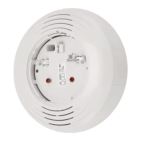
B200S-LF
Low Frequency Intelligent Sounder Base
This model is compatible with System Sensor Models MDL, MDL3R, MDLW, MDL3W and SYNC-1
SPECIFICATIONS
Base Diameter:
Base Height (less sensor):
Weight:
Operating Temperature Range:
Operating Humidity Range:
External Supply Electrical Ratings
External Supply Voltage:
Standby Current:
Alarm Current:
SLC Electrical Ratings
SLC Operating Voltage:
SLC Standby Current:
Sound Output
High Volume:
Low Volume:
BEFORE INSTALLING
Read System Sensor's Applications Guide for System Smoke Detectors
(SPAG91), which provides detailed information on sensor spacing, placement,
zoning, wiring, and special applications. This manual is available from System
Sensor. NFPA 72 and NEMA guidelines should be observed. The National Fire
Alarm Code, NFPA 72, requires effective January 1, 2014, that audible appli-
ances installed in sleeping areas produce a low frequency alarm signal that
shall be a square wave or provide equivalent awakening ability with a funda-
mental frequency of 520 Hz +/– 10%.
NOTE: 200 Series sounder bases are not compatible with remote test capable
200 series detectors.
NOTICE: This manual should be left with the owner/user of this equipment.
IMPORTANT: The detector used with this base must be tested and maintained
regularly following NFPA 72 requirements. The detector should be cleaned at
least once a year.
GENERAL DESCRIPTION
The B200S-LF low frequency sounder base is used with System Sensor 200-Se-
ries sensor heads or equivalent. For a list of compatible sensors, refer to the
System Sensor website at www.systemsensor.com. Refer to the appropriate
manual for more information on sensors.
The B200S-LF low frequency sounder base generates a low frequency tone
around 520 Hz. Studies have shown that low frequency audible devices that op-
erate around 520 Hz are more effective in waking individuals in sleeping areas.
The sounder base is capable of producing a variety of tone patterns, including
the distinctive three-pulse temporal pattern (ANSI Temporal 3) fire alarm sig-
nal now required by NFPA 72 for commercial and residential applications. The
B200S-LF offers maximum flexibility in configuration and operation to meet or
exceed the requirements of UL268 and UL464 for Continuous, Temporal 3 and
March time patterns. The temporal 4 pattern meets all requirements of UL268
and UL2075, as well as, private mode setting of UL 464.
The B200S-LF can be commanded by the Fire Alarm Control Panel to adopt
the address of the attached sensor head, but as a unique device type on the
loop. By using the address, the fire alarm control panel can command an
individual sounder base to activate, or a group of sounders in a suite or other
multi-room configuration. The command set from the panel can be tailored to
the specific event, allowing selection of volume, tone, and group. The device
offers two volume levels: 75 dBA and 85 dBA. The available tones are Contin-
uous, ANSI Temporal 3, ANSI Temporal 4, and March Time. In addition, some
fire alarm panels will offer the ability to command a custom tone pattern.
Refer to the appropriate fire alarm control panel manual for more information.
In addition, the B200S-LF is equipped with the circuitry to recognize the
System Sensor synchronization protocol, enabling the sounder base to be
6.875 inch (17.46 cm)
2.0 inch (5.08 cm)
0.6 lb. (272 gm)
Refer to applicable sensor Operating Temperature Range using the Base/Sensor Cross Reference Chart at systemsensor.com
10% to 93% relative humidity (non-condensing)
16 to 33 VDC (VFWR)
550 μA maximum VDC
High volume setting: 70 mA maximum @ 33.0 VDC
90 mA maximum @ 24.0 VDC
140 mA maximum @16.0 VDC
15 to 32 VDC
300 μA maximum (base only, refer to applicable sensor specification)
Greater than 85 dBA minimum measured in a UL reverberant room at 10 feet, 24 Volts (in continuous tone)
Greater than 75 dBA minimum measured in a UL reverberant room at 10 feet, 24 Volts (in continuous tone)
Low volume setting: 15 mA maximum @ 33.0 VDC
used as a component of the general evacuation signal – producing an NFPA
72 compliant Temporal 3 pattern in synchronization with other System
Sensor notification devices. This requires connection to a power supply
capable of generating the System Sensor synchronization pulses, a FACP NAC
output configured to System Sensor synchronization protocol, or a separate
synchronization module.
The sounder base is intended for use with intelligent systems. In addition to
being connected to the SLC, the sounder base requires a connection to either
24 VDC constant power or a NAC circuit, depending on the FACP and intended
use. The connections for 24V constant/NAC power and the communication
loop are isolated to prevent electrical interaction between them.
When connected to a NAC, power is supervised via the NAC circuit supervision
while in standby mode (EOL resistor required for Class B operation). when
activated, the B200S-LF provides supervision of NAC power (see Figure 5).
When using a FACP equipped with a "sounder base standby power monitor-
ing" mode (see table) and constant 24 V power, power supervision EOL de-
vices (supervision relays and resistors) should not be used (see Figure 4). In
this case, the B200S-LF will provide supervision in both standby and alarm/
active mode. If your FACP is not listed in the table or you choose not to use
"sounder base standby power monitoring" mode, power supervision relays
and EOL resistors are required to provide supervision in standby mode.
NOTE: If the FACP's "sounder base standby power monitoring" mode is en-
abled, connecting B200S-LF low frequency sounder bases to the NAC will re-
sult in power supervision failure when in standby. Only connect B200S-LF
low frequency sounder bases to constant 24 V power in this case. Refer to the
panel manual for maximum allowable number of units per loop.
NOTE: For NFPA72 Installations, the Temporal 3 tone at high volume should be
used for public mode evacuation. The use of other tone styles and low volume
level will be at the discretion of the local Authority Having Jurisdiction (AHJ).
NOTE: When not used as a supplementary evacuation system, the external 24
VDC supply shall be treated as a component of the main power supply system and
shall fall under the requirements of the main power supply system per NFPA 72.
FACPS EQUIPPED WITH "SOUNDERBASE STANDBY POWER
MONITORING" MODE
Manufacturer
FACP Model
Notifier
NFS-320
Notifier
NFS2-640
Notifier
NFS2-3030
Gamewell-FCI
E3 Series
1
3825 Ohio Avenue, St. Charles, Illinois 60174
1-800-SENSOR2, FAX: 630-377-6495
www.systemsensor.com
20 mA maximum @ 24.0 VDC
25 mA maximum @ 16.0 VDC
Firmware Revision
Rev. 20 or Higher
Rev. 20 or Higher
Rev. 20 or Higher
Rev. 2.4 or Higher
I56-4151-003R
06-10
Advertisement
Table of Contents

Related Manuals for System Sensor B200S-LF


Summary of Contents for System Sensor B200S-LF
- Page 1 INSTALLATION AND MAINTENANCE INSTRUCTIONS B200S-LF Low Frequency Intelligent Sounder Base 3825 Ohio Avenue, St. Charles, Illinois 60174 1-800-SENSOR2, FAX: 630-377-6495 This model is compatible with System Sensor Models MDL, MDL3R, MDLW, MDL3W and SYNC-1 www.systemsensor.com SPECIFICATIONS Base Diameter: 6.875 inch (17.46 cm) Base Height (less sensor): 2.0 inch (5.08 cm)
- Page 2 (+ and -) wires 1. Via the fire alarm control panel, command the individual B200S-LF to acti- and the communication circuit wires should be twisted pair or shielded cable vate using the associated sensor address. That sounder base should sound installed in a separate grounded conduit to protect the communication loop in approximately five seconds.
- Page 3 FIGURE 4: WIRING DIAGRAM (CONNECTED TO 24V POWER USING COMPATIBLE FACP WITH “SOUNDER BASE STANDBY POWER MONITORING” ENABLED) NOTE: Only use this wiring diagram when connecting to 24VDC power using a FACP listed in the table on page 1. Please consult your FACP manufacturer for panel-specific wiring configurations and special cases.
- Page 4 SLAVE SLAVE – – C1090-00 TEMP JUMP OFF NOTE: Wiring shown for System Sensor MDL Series Sync Module. For additional wiring configurations, see your sync module manual. FIGURE 7A: BREAK TAB AT USE SMALL-BLADED DOTTED LINE BY SCREWDRIVER TO PLASTIC LEVER...
Need help?
Do you have a question about the B200S-LF and is the answer not in the manual?
Questions and answers