Table of Contents
Advertisement
3916066 09.06
EW 40
Wireless Fan Control
Product Information
Mechanical Installation
Electrical Installation
Start Up and Configuration
Maintenance and Troubleshooting
EXHAUSTO Inc.
1200 Northmeadow Pkwy.
Suite 180
Roswell, GA 30076
........................ Chapter 1 + 2
......................... Chapter 3
............................. Chapter 4
.................. Chapter 5
P: 770.587.3238
F: 770.587.4731
T: 800.255.2923
info@exhausto.com
us.exhausto.com
Installation & Operating Manual
USA
CAN
...... Chapter 6
Job Name:
Installer:
Installation Date:
Advertisement
Table of Contents

Related Manuals for Exhausto EW 40


Summary of Contents for Exhausto EW 40
- Page 1 Installation & Operating Manual 3916066 09.06 EW 40 Wireless Fan Control Product Information ......Chapter 1 + 2 Mechanical Installation ......Chapter 3 Electrical Installation ......Chapter 4 Start Up and Configuration ....Chapter 5 Maintenance and Troubleshooting ..Chapter 6...
-
Page 2: Symbol Legend
1. Product Information 1.1 Function ....................3 1.2 Shipping ....................3 1.3 Warranty ....................3 1.4 FCC Notifications and Requirements............4 1.5 EW 40 Control Components and Locations..........5 2. Specifications 2.1 Dimensions & Capacities ..............6 3. Mechanical Installation 3.1 Installing the Power Unit ..............7 3.2 Installing the Control Unit ..............7... -
Page 3: Warranty
1. Product Information 1.1 Function The EW 40 is a wireless control that can be used to operate and control an EXHAUSTO chimney fan or power venter. It is designed for use with fireplaces and stoves. The use is not restricted to any type of fuel. The unit allows the user to stop, start and control the speed of a chimney fan from a wireless Control Unit. It can be installed with or without a temperature sensor. For gas-fired appliances, a safety system in the form of a... - Page 4 Changes or modifications not expressly approved by the party responsible for compliance could void the user’s authority to operate the equipment. Notice: FCC Part 15- Class B Digital Device or Peripheral This equipment has been tested and found to comply with the limits for a Class B digital device, pursuant to part 15 of the FCC Rules. These limits are designed to provide reasonable protection against harmful interference in a residential installation. This equipment generates, uses and can radiate radio frequency energy and, if not installed and used in accordance with the instructions, may cause harmful interference to radio communications. However, there is no guarantee that interference will not occur in a particular installation. If this equipment does cause harmful interference to radio or television reception, which can be determined by turning the equipment off and on, the user is encouraged to try to correct the interference by one or more of the following measures: Reorient or relocate the receiving antenna. Increase the separation between the equipment and receiver. Connect the equipment into an outlet on a circuit different from that to which the receiver is connected. Consult the dealer or an experienced radio/TV technician for help. NOTE: The label below appears on the EW 40 Power Unit.
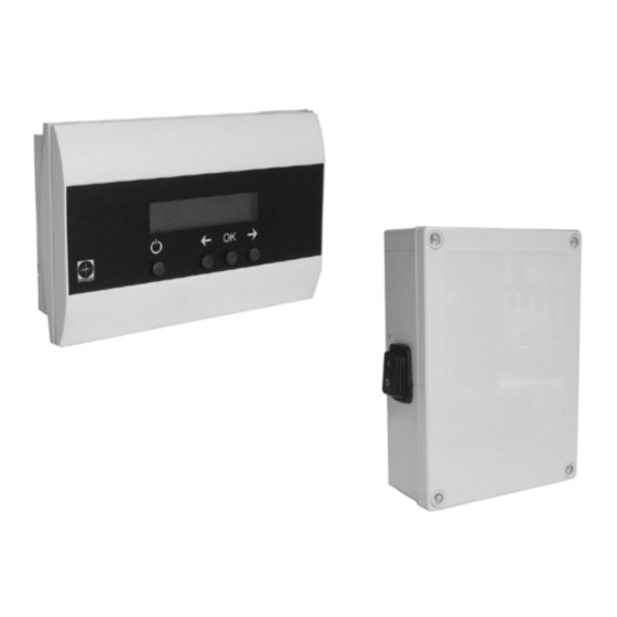
- Page 5 1.5 EW 40 Control Components and Locations The EW 40 Control is made up of a Control Unit, Power Unit and an optional Repeater Unit (see Figure 1). The Control Unit serves as the user interface for the system. It transmits a wireless signal to the Power Unit to initiate fan functions. In some cases, it may be necessary to install a Repeater Unit to obtain sufficient communication in...
- Page 6 3916066 09.06 2. Specifications 2.1 Dimensions & Capacities Control Unit EW 40 Control Unit Power Supply 2 x 1.5V C-batteries Battery Life Approx. 1 year Operating Temperature °F/°C 32 to 104 / 0 to 40 Material ABS Plastic Dimensions A in/mm 5.94 / 151...
-
Page 7: Installation
3916066 09.06 3. Installation 3.1 Installing the Power Unit The Power Unit can mounted outdoors and should be mounted onto or near the chimney where the chimney fan is mounted and no more than 3 feet (1 meter) from the fan. Proceed as follows: •... -
Page 8: Installing The Temperature Sensor
4. Secure the sensor bracket with the two sheet metal screws provided. Fig. 5 3.4 Installing the Proven Draft Switch (if applicable) If the EW 40 is used to control a gas-fired heating appliance, a Proven Draft Switch (not included) must be installed. A PDS-1 is available from EXHAUSTO and is installed as shown below. For wiring details see Figure 10. Please consult the PDS-1 product manual for in depth installation instructions. Fig. 6 Fig. 7... -
Page 9: Control Unit
3916066 09.06 3.5 Installing the Repeater Unit (if applicable) A Repeater Unit is typically used in installations that require the Control Unit to be placed far away from the Power Unit and in those where the communication signal is transmitted through multiple obstructions Fig. 8 Fig. 9 Repeater Unit Control Unit A B C Receive... -
Page 10: Electrical Installation
EW 40 THIS DIAGRAM FOR THE WIRING OF Chimney Power Unit A PROVEN DRAFT SWITCH IS ONLY Probe USED WHEN THE EW 40 IS USED WITH GAS-FIRED APPLIANCES EW 40 Repeater Unit (if needed) PDS, Proven PROVEN DRAFT Draft Switch... - Page 11 3916066 09.06 4.2 Wiring of EW 40 To ease wiring of the control, please follow these step-by-step instructions: Wiring of the Power Unit/chimney fan: Run wires through 1/2” weathertight conduit from the junction box supplied with the chimney fan to the Power Unit. Connect the wires from the fan junction box to terminals 8, 9 and 10 shown on the diagram below. Connect the temperature sensor to terminals 6 and 7 as shown in the diagram below.
-
Page 12: Main Menu Sub-Menus
3916066 09.06 5. Startup and Configuration 5.1 Control Unit Settings Accessing the Set-Up Menu. To access this menu, press the “OK” button (B) and hold it down for at least 3 seconds. To exit the menu, press the ON/OFF button (D). Use the arrow buttons (A and C) to scroll back and forth between the various menu items. The menu setting are show in the table. -
Page 13: Recommended Settings
In case technical problems occurs, check the list below for possible solutions. This list does not necessarily include all possible problem, so if the list below does not cover your problem, call EXHAUSTO at the number listed on the back of the manual:...
Need help?
Do you have a question about the EW 40 and is the answer not in the manual?
Questions and answers