Table of Contents
Advertisement
Quick Links
3001435 05.12
EBC 12
Modulating Fan Control
Product Information
Mechanical Installation
Electrical Installation
Start Up and Configuration
Maintenance and Troubleshooting
READ AND SAVE THESE INSTRUCTIONS!
ENERVEX Inc.
1685 Bluegrass Lakes Pkwy.
Alpharetta, GA 30004
.............................. Chapters 1+2
......................... Chapter 3
............................. Chapter 4
.................. Chapter 5
P: 770.587.3238
F: 770.587.4731
T: 800.255.2923
info@enervex.com
www.enervex.com
Installation & Operating Manual
USA
CAN
...... Chapter 6
Job Name:
Installer:
Installation Date:
V E N T I N G D E S I G N S O L U T I O N S
VOLKO SUPPLY
800-685-8263
Advertisement
Table of Contents

Subscribe to Our Youtube Channel
Related Manuals for Exhausto EBC 12


Summary of Contents for Exhausto EBC 12
- Page 1 Installation & Operating Manual 3001435 05.12 EBC 12 VOLKO SUPPLY 800-685-8263 Modulating Fan Control Product Information ......Chapters 1+2 Mechanical Installation ......Chapter 3 Electrical Installation ......Chapter 4 Start Up and Configuration ....Chapter 5 Maintenance and Troubleshooting ..Chapter 6...
-
Page 2: Symbol Legend
System design documentation is available from any 2. Before servicing or cleaning the unit, switch off at service panel authorized EXHAUSTO representative. and lock service panel to prevent power from being switched on Accessories, fans and variable frequency drives are not covered by accidentally. -
Page 3: Warranty
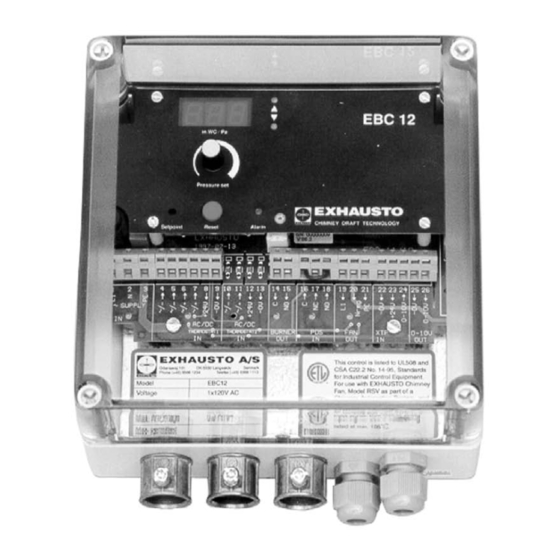
The use of the EBC 12 is not restricted to any type of fuel or type of heating appliance. When the appliance thermostat closes and calls for heat, the control will send maximum voltage to the chimney fan or VFD. When the necessary draft is achieved, the control will allow boiler firing and regulate the voltage... - Page 4 3001435 05.12 2. Specifications 2.1 Dimensions & Capacities EBC 12 Control Power supply 1x120VAC In. WC / Pa Amperage Setpoint Reset Alarm Operating temperature °F/°C -4 to 122 / -20 to 50 Range of operation inWC/Pa 0-0.6 / 0-150 Tolerance inWC/Pa 0.01 / 3 +/-10%...
- Page 5 The distance between the control and the transducer should not exceed three hundred (300) feet. Fig. 3 EBC 12 V E N T I N G D E S I G N S O L U T I O N S...
-
Page 6: Mounting Of Transducer
3001435 05.12 3.3 Mounting of Transducer Attention must be paid to the location of the transducer. The transducer can be mounted in any orientation but prefer ably with the pressure ports facing down. The transducer should be mounted within six (6) feet of the stack probe. Fig. 4 3.4 Mounting of Stack Probe The probe (Fig. - Page 7 3001435 05.12 4. Electrical Installation 4.1 General Danger: Turn off electrical power before servicing. Contact with live electric components can cause shock or death. EBC 12 is designed for 1x120VAC power supply only. Fan output is regulating on the neutral side and cannot be connected to other circuits. The control can be used in two ways: • Connected so the fan runs continuously independent of appliance operation (see paragraph 4.2). • Interlocked with an appliance so the appliance operation indirectly controls the fan operation (see paragraph 4.3). In both cases the control will still monitor and maintain a constant draft. There are two types of safety systems available: • Integrated Proven Draft Switch (standard).
- Page 8 3001435 05.12 4.2 Continuous Chimney Fan Operation Fig. 7 shows how to connect a chimney fan to the EBC 12 if continuous operation is needed: • Connect the power supply to terminals 1, 2 and 3. • Jump terminals 5 and 9. • Jump terminals 6 and 8. • Connection to the appliance(s): - Connect the start signal from the burner to terminals 14 and 15.
- Page 9 The control can be interlocked with an appliance in two ways: It can be interlocked directly with an appliance control, or with a dry set of contacts. Interlock with Burner Figure 8 shows how an appliance control signal (10-120V AC/DC) is connected to the EBC 12: • Connect the power supply to terminals 1, 2 and 3. • Connection to the appliance: - Connect the boiler start signal to terminal 4.
- Page 10 3001435 05.12 Interlock with dry set of contacts Figure 9 shows how a dry set of contacts is connected to the EBC 12: • Connect the power supply to terminals 1, 2 and 3. • Connection to the appliance: Connect the dry set of contacts to terminals 6 and 8. Jump terminals 4 and 9.
-
Page 11: Connection To A Variable Frequency Drive
3001435 05.12 4.4 Connection to a Variable Frequency Drive To connect the 3-phase fan and variable frequency drive (VFD), connect the VFD to terminals 25 and 26 of the EBC 12. DO NOT connect the fan directly to the control. - Page 12 3001435 05.12 4.5 Integrated Proven Draft Switch with External Proven Draft Switch Backup Fig. 12 shows how to connect a external Proven Draft Switch (PDS) to the EBC 12. The external PDS is a backup to the integrated PDS and both must be satisfied by sufficient draft to release the appliance: • Remove the factory installed jumper over terminals 16 and 18. • Connect the switch to terminals 16, 17 and 18 as shown on Fig. 11. Fig. 12 EBC 12 Control Board...
-
Page 13: Dip Switch Settings
3001435 05.12 5. Startup and Configuration 5.1 General Prior to start up please review the paragraph below titled Dipswitch settings. Dipswitch settings Prior to starting the system, check to see if the dipswitch settings are as required: • Default factory setting: All OFF • If the factory setting must be changed, the black cover plate must be removed to gain access to the dipswitches (see Fig 12-A): 1. - Page 14 5.2 Setting Operating Pressure The pressure setting of the EBC 12 must be adjusted to assure proper draft for the heating system. The display (Fig. 13-C) has two functions. It can show what the draft set-point is, and it can show what the actual draft is.
-
Page 15: Maintenance And Troubleshooting
3001435 05.12 6. Maintenance and Troubleshooting Observation Problem Solution No light in the SUPPLY diode (Fig 15-A) Blown fuse or interrupted power supply 1) Check the fuse (Fig. 15-B) and the fan power. 2) Check the power supply. Constant light in “Increasing Speed” diode System fault 1) Check that the probe is connected to the “-” port on the (Fig 15-E) XTP2 transducer. - Page 16 3001435 05.12 ENERVEX Inc. P: 770.587.3238 1685 Bluegrass Lakes Pkwy. F: 770.587.4731 Alpharetta, GA 30004 T: 800.255.2923 V E N T I N G D E S I G N S O L U T I O N S info@enervex.com www.enervex.com...
Need help?
Do you have a question about the EBC 12 and is the answer not in the manual?
Questions and answers