Table of Contents
Advertisement
Quick Links
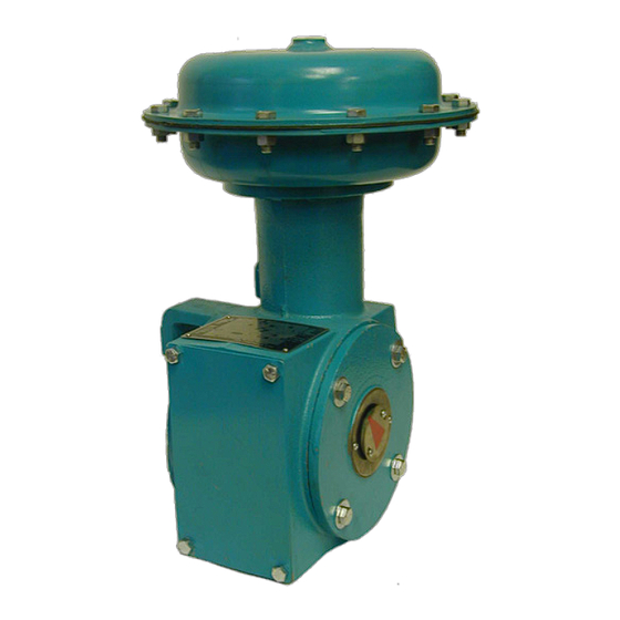
CVS Series 1051/1052
Rotary Actuator
Sizes 30 - 70
All CVS Controls actuators are to be installed and
maintained in accordance with instructions supplied
by CVS Controls.
This manual includes information on installing,
maintaining and adjusting the CVS Series 1051
Actuator, sizes 30 to 60, and Series 1052, sizes 40-
70. For information on other equipment used with
these actuators, consult the appropriate manuals.
Introduction
The CVS Series 1051/1052 Diaphragm Rotary
Actuator is a pneumatic spring-return actuator
designed for use with rotary-shaft control valves.
This is a direct-acting actuator, and an increase in
the loading pressure extends the diaphragm rod out
of the spring barrel. The CVS Type 1051/1052
Actuator is suitable for on-off service, or for
throttling service when used with a valve positioner.
The Series 1052 Actuator includes a spring
adjuster, which is suitable for use with or without a
positioner.
The stroking time is dependent on the actuator size,
rotation, spring rate, initial spring compression and
supply pressure. If the stroking time is critical for
your application, consult CVS Controls Ltd. for
proper settings.
The travel indicator is a combination graduated disk
and pointer located on the actuator end of the valve
shaft. Fixed travel stops are an available option.
Refer to Table 1 for additional specifications for the
CVS Series 1051/1052 Actuator. Additional
information specific to the actuator as shipped from
the factory are stamped on the nameplate
(Figure 2) installed on the actuator.
Head Office
3900 – 101 Street
Edmonton, Alberta, Canada T6E 0A5
Office: (780) 437-3055
Fax: (780) 436-5461
Website: www.cvs-controls.com
CVS Series 1051 Actuator
Installation
When the actuator and the valve are shipped
together from CVS Controls Ltd., the actuator is
usually mounted onto the valve. Refer to the valve
body instruction when installing the valve into the
pipeline, and then follow the instructions in the
Loading Connections portion of this manual.
If the actuator has been shipped separately, or if it is
necessary to mount the actuator onto the valve, refer
to procedures in the Actuator Mounting portion of this
manual.
E-Mail: info@cvs-controls.com
Instruction Manual
CVS Series 1052 Actuator
Calgary Sales Office
3516 114 Avenue SE
Calgary, Alberta, Canada T2Z 3V6
Office: (403) 250-1416
Fax: (403) 291-9487
1
Advertisement
Table of Contents

Related Manuals for CVS 1051 Series

Summary of Contents for CVS 1051 Series
- Page 1 Instruction Manual CVS Series 1051/1052 Rotary Actuator Sizes 30 - 70 All CVS Controls actuators are to be installed and maintained in accordance with instructions supplied by CVS Controls. This manual includes information on installing, maintaining and adjusting the CVS Series 1051...
-
Page 2: Actuator Mounting
Table 1: CVS Series 1051/1052 Actuator Specifications Operating Principle Direct Acting Actuator Sizes 1051: 30, 40, 60 1052: 40, 60, 70 Size 30 80 psig (5.5 bar) Size 30 Maximum Diaphragm Size 40 Size 40 65 psig (4.5 bar) Maximum Diaphragm 75 psig (5.2 bar) - Page 3 2 & 43 actuator turnbuckle before proceeding to the Loading Connection portion of installation. CVS Design V100 Mounting Action Valve PDTC Right-Hand PDTO PDTC Left-Hand PDTO 1. PDTC: Push-Down-To-Close; PDTO: Push-Down-To-Open Figure 3: Mounting Styles and Positions for CVS Type 1051 Actuator...
-
Page 4: Loading Connection
If a valve positioner is part of the assembly, the connection will likely be made at the CVS Controls factory. INLET INLET INLET INLET INLET INLET INLET INLET Figure 4: CVS Type 1051 Actuator-Valve Mounting... -
Page 5: Turnbuckle Adjustment
Turnbuckle Adjustment 1. Remove the access plate (Key 11) and machine Warning: The sudden release of process screws (Key 29) if included. fluid can cause personal injury or property 2. Loosen the lower locknut (Key 14). damage. Prior to starting adjustment 3. -
Page 6: Principle Of Operation
(Keys 2, 42 and 43) should not be diaphragm casing and the diaphragm (Key 25). removed. 9. Refer to the warning on the CVS Controls nameplate (Key 27) located on the diaphragm Note: Cap screw (Key 12) must be plate (Key 1). - Page 7 Disassembly continued, 4. Coat the thread of the cap screw (Key 24) as well as the tapered end of the diaphragm rod Warning: The diaphragm plate (Key 1) may (Key 22) with an appropriate lubricant. be lodged against the diaphragm rod (Key 5.
-
Page 8: Changing Actuator Mounting
Assembly continued, Correct lever/valve shaft positioning is important in ensuring proper valve action. Refer to the 9. Ensure that the warning nameplate (Key 27) is in appropriate valve body instruction manual. place and install the diaphragm (Key 25) and the upper diaphragm casing (Key 26). -
Page 9: Parts Ordering
The serial number for your CVS Series 1051/1052 8. Apply thread locking compound to the threads of Rotary Actuator is located on the nameplate (Figure the cap screw (Key 12). -
Page 10: Cvs Type 1051 Rotary Actuator
Figure 8: Typical CVS Type 1051 Actuator Assembly cont’d CVS Type 1051 Rotary Actuator Parts List Description Part Number Description Part Number Size 30 CVS2F649319042 Size 30 CVS1A553424052 Diaphragm Plate, Cap Screw, pl Size 40 CVS2V939919042 Size 40 CVS1A361524052 cast iron... - Page 11 CVS Type 1051 Rotary Actuator Parts List Description Part Number Description Part Number Spring Barrel, Size 40 CVS32A9325X012 Mounting Yoke See Following Table aluminum Size 60 CVS42A9327X012 Retaining Ring, Size 30 & 40 CVS12A9409X012 Size 40 CVS32A9325X022 zn pl steel...
- Page 12 CVS Type 1051 Rotary Actuator Parts List Key 34 Bushing, TFE Key 35 Yoke-Bushing Assembly Valve Shaft Key 35 Actuator Diameter Key 34 Yoke-Bushing Size Bushing, TFE Assembly Cast Iron & TFE 12.7 CVS1U902599402 CVS12A9779X0A2 19.1 CVS12A9556X012 CVS12A9799X0C2 22.2 CVS12A9557X012 CVS12A9799X0E2 25.4...
- Page 13 CVS Series 1052 Size 40 Assembly...
- Page 14 Series 1052 Size 40 Assembly – Parts List...
- Page 15 Series 1052 Size 60 Assembly...
- Page 16 CVS Series 1052 Size 60 Assembly – Parts List...
- Page 17 CVS Series 1052 Size 70 Assembly...
- Page 18 CVS Series 1052 Size 70 Assembly – Parts List...
- Page 19 CVS Series 1051/1052 Dimensional Data – inches...
- Page 20 Email: info@cvs-controls.com CVS Controls Ltd. strives for the highest levels of quality and accuracy. The information included in this publication is presented for informational purposes only. CVS Controls Ltd. reserves the right to modify or change, and improve design, process, and specifications without written notice. Under no circumstance is the information contained to be interpreted to be a guarantee/warranty with regard to our products or services, applicability or use.
Need help?
Do you have a question about the 1051 Series and is the answer not in the manual?
Questions and answers