Table of Contents
Advertisement
Quick Links
Installer's Guide
ZZSENSAL0400AA
Remote Indoor Temperature Sensor
( Use with *CONT402 Comfort Controls)
ALL phases of this installation must comply with NATIONAL, STATE AND LOCAL CODES
APPLICATION
This Wall Mount Temperature Sensor is used with the
*CONT402 Comfort Control.
SPECIFICATIONS
Operating Ambient Temperature Range:
20° to 120°F (-6.7° to 48.9°C).
Display Range:
20° to 120°F (-6.7° to 48.9°C).
Sensor Accuracy:
+/-.5°F at 75°F
Operating Relative Humidity:
5% to 90% non-condensing.
Finish:
White.
Dimensions in in. (mm):
1.54 (39) wide x 1.93 (49) high x .745 (19) deep.
Storage Temperature:
-40° to 140°F (-40° to 60°C)
INSTALLATION
When Installing this Product...
1.
Read these instructions carefully. Failure to follow them
could damage the product or cause a hazardous condi-
tion.
2.
Check the ratings given in the instructions and on the
product to make sure the product is suitable for your
application.
▲
t i o n
!
Disconnect power supply before connecting wiring.
Failure to do so may cause equipment damage.
3.
Installer must be a trained, experienced service techni-
cian.
4.
After installation is complete, check out product opera-
tion as provided in these instructions.
Location and Mounting (Fig. 2)
▲
!
If the Remote Indoor Temperature Sensor fails, control
reverts to the on-board temperature sensor. Therefore, the
Comfort Control must be installed in the conditioned space.
1.
Choose a location for mounting the Sensor on an inside
wall about 5 ft. (1.5m) above the floor.
2.
Be sure cable distance between the Sensor and
the Comfort Control is less than 200 feet.
CAUTION
CAUTION
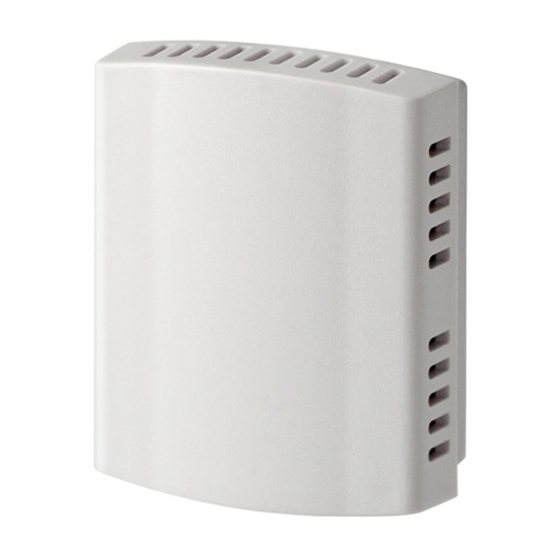
Fig. 1. ZZSENSAL0400AA Sensor.
3.
Make sure there is good air circulation at average
temperature at the chosen location. Avoid the following
locations because they can introduce errors in sensor
measurements. See Fig. 2.
a. Hot areas caused by:
(i)
Concealed pipes or ducts.
(ii) Drafts from fireplaces or other heat
sources.
(iii) Convection or radiant heat from the sun
or electrical equipment.
b. Cold areas caused by:
(i)
Concealed pipes or ducts.
(ii) Drafts from windows and doors.
(iii) Unheated areas on the other side of the
wall location.
c. Dead air areas:
(i)
Behind doors, furniture and curtains.
(ii) In corners and alcoves.
4. Remove remote indoor sensor cover by grasping the cover at
the top and the bottom and gently pulling it straight off
the subbase. Position and level the subbase (for appear-
ance only). Device functions correctly even when not level.
5. Use a pencil to mark the wiring opening hole. Remove the
subbase from the wall and drill one hole in the wall for
the wiring opening.
6. Run wire cable to the wiring opening hole at the selected
wall location. Pull approximately three inches of wire
through the wiring opening in the wall. 18-gauge thermo-
stat wire is recommended.
7. Position and level the subbase on the wall with the thermo-
stat wire protruding through the wiring opening hole of
the subbase. Slide the subbase a short distance up the
wall until the thermostat wire rests against the bottom
18-HD31D1-1
Advertisement
Table of Contents

Related Manuals for American Standard ZZSENSAL0400AA


Summary of Contents for American Standard ZZSENSAL0400AA
-
Page 1: Specifications
5% to 90% non-condensing. Finish: White. Dimensions in in. (mm): Fig. 1. ZZSENSAL0400AA Sensor. 1.54 (39) wide x 1.93 (49) high x .745 (19) deep. Storage Temperature: Make sure there is good air circulation at average -40° to 140°F (-40° to 60°C) temperature at the chosen location. - Page 2 IF MORE THAN ONE REMOTE SENSOR IS REQUIRED, REFER TO FIGURE 5. Disconnect power supply before connecting wiring. Failure to do so may cause equipment damage. SINGLE A 402 Fig. 3. Wiring a single Sensor. Pub. No. 18-HD31D1-1 © 2005 American Standard Inc. All Rights Reserved...
- Page 3 Installer’s Guide Fig. 6. Room Temperature Reading on *CONT402 Comfort Control. OPERATION Once installed and the Comfort Control Installer Setup is complete, the remote inside temperature is displayed on the Comfort Control Home Screen as the Room Temperature. See Fig. 6. The Remote Indoor Temperature Sensor converts room temperature to a resistance that the Comfort Control can Fig.
- Page 4 6.4K 36.7 6.1K 37.8 5.8K American Standard Inc. 6200 Troup Highway Tyler, TX 75707 Since the manufacturer has a policy of continuous product and product data improvement, it reserves the right to For more information contact your local dealer (distributor)
Need help?
Do you have a question about the ZZSENSAL0400AA and is the answer not in the manual?
Questions and answers