Advertisement
Installer's Guide
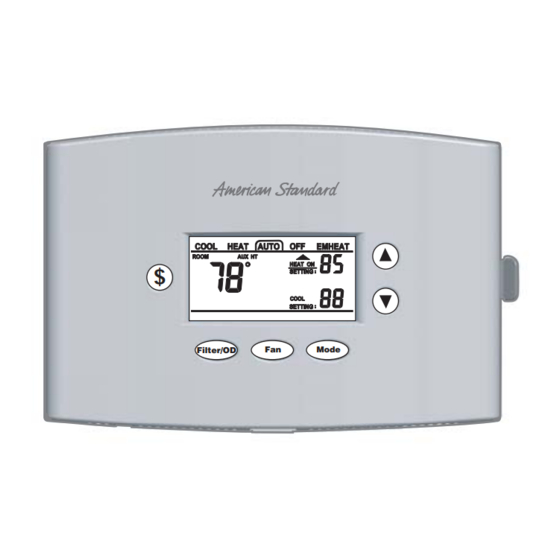
Premium
ACONT401AN21MA
2 Heat (Gas, Oil* or Elec) / 1 Cool / Heat Pump
(Factory set for 2H/1C gas applications)
Electronic Non-Programmable
3 - 9 Wire Hookup (2 for outdoor sensor)
ALL phases of this installation must comply with NATIONAL, STATE AND LOCAL CODES
Note: Read the entire instruction manual before starting the
installation.
Contents
Introduction ........................................................................ 1
Application .......................................................................... 1
Product Specifications ...................................................... 1
Installation .......................................................................... 2
Mounting and Wiring .......................................................... 2
SETUP ................................................................................. 3
Checkout ............................................................................. 4
Troubleshooting ................................................................. 6
Features .............................................................................. 7
Introduction
ACONT401AN21MA is a digital non-programmable 2Heat/1
Cool/Heat Pump/Heat-Cool wall mounted low voltage
(24VAC) Comfort Control with backlit LCD and keypad. It
maintains room temperature by controlling the operation of
heating, cooling and heat pump systems. The Comfort
Control is easily configured for heat pump or cooling only and
gas or electric heat applications via the user friendly In-
staller Setup menu. The Comfort Control features include
separate heating and cooling setpoints, selectable auto or
manual changeover, adjustable energy saving mode, adjust-
able filter reminder, outdoor temperature sensing, LitePort
technology for extended system diagnostics and fault notifica-
tion. Setup selections and diagnostics are stored indefinitely
in the Comfort Controls nonvolatile memory eliminating the
need for battery backup.
Safety Considerations
Read the following manufacturer instructions carefully.
Follow all local codes during installation. All wiring must
conform to local and national electrical codes. Improper
wiring or installation may damage comfort control.
Recognize safety information. This is the safety alert symbol
▲
!
. When you see this symbol on the equipment and in the
instruction manual, be alert to the potential for personal
injury.
Understand the signal words DANGER, WARNING and
CAUTION. These words are used with the safety-alert
symbol. DANGER identifies the most serious hazards which
will result in severe personal injury or death. WARNING
signifies a hazard which could result in personal injury or
death. CAUTION is used to identify unsafe practices which
could result in minor personal injury or product and prop-
erty damage.
$
Filter/OD
Application
Heat Pump or A/C
1 Stage Heat Pump**, 1 Stage Aux Heat.
1 Stage Heat Pump**, 0 Stage Aux Heat.
1 Stage Cool, 2 Stage Heat (Gas, Electric or Oil*).
1 Stage Cool, 1 Stage Heat (Gas, Electric or Oil*).
1 Stage Cool, 0 Stage Heat.
0 Stage Cool, 2 Stage Heat (Gas, Electric or Oil*).
0 Stage Cool, 1 Stage Heat (Gas, Electric or Oil*).
* Requires external relay for oil furnace applications.
** External TAYPLUS103A required for dual fuel applica-
tions.
BAYSEN01ATEMPA required for outdoor temperature
sensing and display
SYSTEM MODE: Heat, Cool, Auto, Emergency Heat and Off
FAN MODE: Auto or On
Product Specifications
- Power Source: 20-30VAC, Class II, 50/60Hz.
- Cooling setpoint temperature range: 65F - 90F,
18.0C - 33.0C, 1F and 0.5C resolution.
- Heating setpoint temperature range: 40F- 85F,
5.0C - 30.0C, 1F and 0.5C resolution.
- Default set points: 68F, 20.0C Heat, 78F, 25.5C Cool
- Storage Range: -40F to 140F, 5% - 90% RH non-
condensing.
- Operating Temperature range: 32F - 110F, 5 - 90% RH
non-condensing.
- Outdoor Temperature Display Range: -40F - 140F.
- Minimum Cycle Off Time Delay: Cooling - 5 minutes,
Heating - 1 minute.
- Use minimum 18 gauge NEC approved control
wiring.
11-HD03D2-3
Fan
Mode
FIG
Fig. 5
Fig. 5
Fig. 3
Fig. 4
Fig. 4
Fig. 3
Fig. 4
Advertisement
Table of Contents

Related Manuals for American Standard ACONT401AN21MA


Summary of Contents for American Standard ACONT401AN21MA
- Page 1 Troubleshooting ..............6 Features ................7 Application Introduction Heat Pump or A/C ACONT401AN21MA is a digital non-programmable 2Heat/1 1 Stage Heat Pump**, 1 Stage Aux Heat. Fig. 5 Cool/Heat Pump/Heat-Cool wall mounted low voltage 1 Stage Heat Pump**, 0 Stage Aux Heat.
- Page 2 Figure 3 gripping the subbase by the mounting holes with the other hand. Lift out and up. See Figure 1. Pub. No. 11-HD03D2-3 © 2006 American Standard Inc. All Rights Reserved...
- Page 3 Installer’s Guide 10.Check the operation of the business card drawer. Verify that it slides in and out without binding. SINGLE STAGE OIL FURNACE - SINGLE STAGE COOLING 11. Reinstall the control on its mounting base by aligning the COMFORT CONTROL SINGLE STAGE control at the top of the mounting base.
- Page 4 Installer’s Guide Checkout There are two methods of verifying that the Comfort Control The Manual test mode will time out and return to normal operates the system as intended. operation after 1 minute from the last key press. Method 1: Normal Mode NOTE: The manual test mode allows the installer to ener- This can be accomplished by pressing the appropriate gize the G fan relay , Table 1, Step 70, and then advance to...
- Page 5 Installer’s Guide Control Setup Table 3 USER SETUP (USU) INSTALLER SETUP (ISU) 1. Set System MODE to OFF. 1. Press and hold MODE and FAN at the same time 2. Set FAN to AUTO. on the normal display screen. 3. Press and hold MODE and UP arrow at the same time. Step Setting (Choices) Menu Item...
- Page 6 Installer’s Guide Troubleshooting Table 4 Troubleshooting Symptom Possible Cause Action 1. Blown fuse or tripped circuit breaker. 1. Replace fuse or reset breaker. 2. Furnace power switch OFF. 2. Turn switch to ON. Display will not come on. 3. Furnace blower compartment door or panel 3.
- Page 7 Installer’s Guide Keypad Lock Features Locking the control’s keypad can help prevent unwanted Cycle Rate tampering or changing the thermostat settings by pressing The selected number of system cycles per hour. If the cycle the controls UP and DOWN arrow keypad buttons at the rate were set to 3, each cycle would be 20 minutes long.
- Page 8 A set of higher gain Proportional-Integral control constants can be chosen to increase the responsiveness of the tem- perature control performance. American Standard Inc. 6200 Troup Highway Tyler, TX 75707 Since the manufacturer has a policy of continuous product and product data improvement, it reserves the right to...
Need help?
Do you have a question about the ACONT401AN21MA and is the answer not in the manual?
Questions and answers