Table of Contents
Advertisement
Advertisement
Table of Contents

Related Manuals for Wilko HG1603WK


Summary of Contents for Wilko HG1603WK
- Page 1 2 BURNER GAS BBQ Assembly instruction (0428786) 0359-17...
-
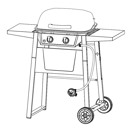
Page 2: Expanded View
Expanded View... -
Page 3: Parts Supplied
Parts Supplied Please check parts against the list below before assembling your Barbecue Grill. Take a few moments to familiarise yourself with the contents. Check that all holes are clear of paint before assembly, if you find a blockage, please use a screw driver to clear the blocked hole. Upper left cart frame Lid handle Upper right cart frame... -
Page 4: Fittings Supplied
Fittings Supplied Heat resistant washer 6 Screw ST4.8X10 Screw M5X14 Lock washer 5 Wing Bolt M5X15 Lock washer 6 Pin 6x30 Bolt M5X16 Cotter pin 1.4x30 Nut M5 Spacer 18x20 Nut M10 Wing Nut M6 Screwdriver M10-M5 Wrench Washer 5 Washer 6 Screwdriver (included), wrench (included) and plastic head hammer (not included) are required to assemble the Barbecue. - Page 5 Assembly Please read all instructions thoroughly before proceeding. Find a large, clean area in which to assemble your barbecue. Please refer to parts list and assembly diagram as necessary. Assembly of the barbecue involves many large components, it is advisable to have two people assemble the unit. STEP 1: A: Attach lower right rear cart frame (18) to lower right front cart frame (21) ((B) Screw 3Pcs).
- Page 6 STEP 3: A: Attach upper left cart frame (13), cart frame insert (16) to lower left cart frame (17) ((A) Screw 4Pcs). Note: - Use plastic head hammer slowly and gently to strike the cart frame insert into those tubes if needed. - Make sure all the screw holes shown in below 2 small diagrams must be faced inward with the correct orientation.
- Page 7 STEP 4: A: Attach upper right cart frame (14), cart frame insert (16) to the assembled lower right cart frame ((A) Screw 4Pcs). Note: - Use plastic head hammer slowly and gently to strike the cart frame insert into those tubes if needed. - Make sure all the screw holes shown in below 2 small diagrams must be faced inward with the correct orientation.
- Page 8 STEP 5: A: Attach upper front panel (19) to the assembled left and right cart frame ((B) Screw 4Pcs). B: Attach lower rear cart frame support (20) to the assembled left and right cart frame ((B) Screw 4Pcs). Note: Make sure the upper front panel is assembled with the correct orientation as shown below. (19) (20) (20)
- Page 9 STEP 7: A: Attach lighting hook (15) to the assembled right cart frame ((C) Wing bolt 1Pc). B: Hang the lighting hook onto wing bolt. (15)
- Page 10 STEP 8: A: Attach bottom hinge (4) to firebowl assembly ((B) Screw 4Pcs / (H) Washer 4Pcs / (K) Lock washer 4Pcs / (E) Wing nut 4Pcs). STEP 9: A: Attach control knob (6) onto valve stem.
- Page 11 STEP 10: A: Attach top hinge (3) to lid (2) ((B) Screw 4Pcs / (H) Washer 4Pcs / (K) Lock washer 4Pcs / (E) Nut 4Pcs). B: Attach lid handle (1) to lid ((J) Heat resistant washer 2Pcs / (I) Washer 2Pcs / (L) Lock washer 2Pcs / (G) Wing nut 2Pcs).
- Page 12 STEP 12: A: Fix 2 bolts (D) into the upper bolt hole of left cart frame and leave 5mm space for hanging the side shelf (10) ((D) Bolt 2Pcs). B: Hang the side shelf (10) onto 2 upper bolt heads. C: Fix another 2 bolts (D) into the lower bolt hole of left cart frame.
- Page 13 STEP 13: A: Fix 2 bolts (D) into the upper bolt hole of right cart frame and leave 5mm space for hanging the side shelf (10) ((D) Bolt 2Pcs) B: Hang the side shelf (10) onto 2 upper bolt heads. C: Fix another 2 bolts (D) into the lower bolt hole of right cart frame.
- Page 14 STEP 14: A: Slide warming rack (7) into holes in lid and firebowl. Note: Look for corresponding holes on side of lid, insert short wire end into lid hole one side at a time. Position warming rack legs into slots on firebowl sides.
- Page 15 STEP 15: A: Place heat plate (9) onto heat plate support. B: Place cooking grid (8) into firebowl assembly. STEP 16: A: Attach grease cup support (12) onto firebowl assembly. B: Place grease cup (11) onto grease cup support. (11) (11) (12) (12)
-
Page 16: General Safety Warnings
General Safety Warnings Important: Read all the safety warnings and assembly instructions before use and retain all information for future reference. • Read assembly instruction enclosed & all the safety warning before using the appliance. Failure to follow instructions could result in death, serious body injury or property loss. •... -
Page 17: Installing Gas Cylinder
Installing Gas Cylinder To operate you will need (1) precision-filled gas cylinder between 11kg and 15kg. Your barbecue will perform better if propane gas cylinder is used. CAUTION: Gas cylinder must be properly disconnected and removed prior to moving this grill. Specification of Gas Cylinder*(*Gas cylinder not included). - Page 18 Connect Gas Cylinder 1. Make sure control knobs are “OFF” position. 2. The regulator rubber hose and regulator are properly and securely connected. 3. The regulator handle is in the “OFF” position. (Figure C). 4. Remove the seal cap from the automatic valve on the gas cylinder. 5.
-
Page 19: Checking For Leaks
Checking for Leaks Burner Connections 1. Make sure the regulator valve and hose connections are securely fastened to the burner and the gas cylinder. Visually check the connection between the burner venture pipe and orifice. Make sure the burner venture pipes fit over the orifice. - Page 20 4. Connect gas cylinder per “Installing Gas Cylinder” section. 5. To turn regulator ON, turn the regulator valve counterclockwise to the “ON” position. (Figure D) Caution: If you are unable to turn the regulator handle to the “ON’’ position, your regulator is not properly connected. Do not force the handle to open.
-
Page 21: Cleaning And Care
5. With lid open or closed, cook until desired internal food temperatures are achieved. 6. Turn grill “OFF” per “Turning off” instruction. For more tips on direct cooking please see “Tips for Better Cookouts and Longer Grill Life”. Indirect Cooking CAUTION: Do not leave grill unattended while preheating, cooking or burning off food residue on “HIGH”. -
Page 22: Technical Specification
6. Place protective cap cover on gas cylinder and store tank outdoors in a well ventilated area out of the direct sunlight. 7. If storing the grill outdoors, cover the grill with a grill cover for protection from the weather. Technical Specification Model Number: HG1603WK Gas Category: I 3+(28-30/37) -
Page 23: Troubleshooting
Troubleshooting Produced in China for Wilko, Roebuck Way, Manton Wood, Worksop, Nottinghamshire, S80 3EG Careline 08000 329 329 www.wilko.com...
Need help?
Do you have a question about the HG1603WK and is the answer not in the manual?
Questions and answers