Advertisement
Advertisement
Table of Contents

Related Manuals for Harley Benton MP-500


Summary of Contents for Harley Benton MP-500
- Page 1 MP-500 MIDI footswitch user manual...
- Page 2 Musikhaus Thomann Thomann GmbH Hans-Thomann-Straße 1 96138 Burgebrach Germany Telephone: +49 (0) 9546 9223-0 E-mail: info@thomann.de Internet: www.thomann.de 01.10.2018, ID: 432466...
-
Page 3: Table Of Contents
1.1.1 Further information........................5 1.1.2 Notational conventions........................ 6 1.1.3 Symbols and signal words......................7 Safety instructions............................. 9 Features............................... 12 Installation..............................13 Connections and controls........................14 Operating..............................22 Technical specifications........................30 Plug and connection assignment....................31 Protecting the environment......................34 MP-500... -
Page 4: General Information
General information General information 1.1 General notes This manual contains important instructions for the safe operation of the unit. Read and follow the safety instructions and all other instructions. Keep the manual for future reference. Make sure that it is available to all those using the device. If you sell the unit please make sure that the buyer also receives this manual. -
Page 5: Further Information
Our online guides provide detailed information on technical basics Online guides and terms. Personal consultation For personal consultation please contact our technical hotline. If you have any problems with the device the customer service will Service gladly assist you. MP-500... -
Page 6: Notational Conventions
General information 1.1.2 Notational conventions This manual uses the following notational conventions: Letterings The letterings for connectors and controls are marked by square brackets and italics. Examples: [VOLUME] control, [Mono] button. Displays Texts and values displayed on the device are marked by quotation marks and italics. Examples: ‘24ch’... -
Page 7: Symbols And Signal Words
Switch on the device. Press [Auto]. ð Automatic operation is started. Switch off the device. 1.1.3 Symbols and signal words In this section you will find an overview of the meaning of symbols and signal words that are used in this manual. MP-500... - Page 8 General information Signal word Meaning DANGER! This combination of symbol and signal word indicates an immediate dangerous situation that will result in death or serious injury if it is not avoided. NOTICE! This combination of symbol and signal word indicates a pos‐ sible dangerous situation that can result in material and environmental damage if it is not avoided.
-
Page 9: Safety Instructions
This device may be used only by persons with sufficient physical, sensorial, and intellectual abilities and having corresponding knowledge and experience. Other persons may use this device only if they are supervised or instructed by a person who is responsible for their safety. MP-500... - Page 10 Safety instructions Safety DANGER! Danger for children Ensure that plastic bags, packaging, etc. are disposed of properly and are not within reach of babies and young children. Choking hazard! Ensure that children do not detach any small parts (e.g. knobs or the like) from the unit.
- Page 11 Failure to do so could result in damage to the device and pos‐ sibly the user. Unplug the external power supply before electrical storms occur and when the device is unused for long periods of time to reduce the risk of electric shock or fire. MP-500...
-
Page 12: Features
Features Features Audio interface with MIDI footswitch for controlling guitar amps or effects devices via mobile end devices and apps (iOS, Mac OS and Android systems) USB MIDI control and standard MIDI control 8 programmable footswitches 2 inputs for effect pedals to control the effect parameters (effect pedals not included) High-speed data transmission of up to 192 kHz/24 bits Pre-programmed configurations for common software or devices, e.g. -
Page 13: Installation
Unpack and check carefully there is no transportation damage before using the unit. Keep the equipment packaging. To fully protect the product against vibration, dust and moisture during transportation or storage use the original packaging or your own packaging material suitable for transport or storage, respectively. MP-500... -
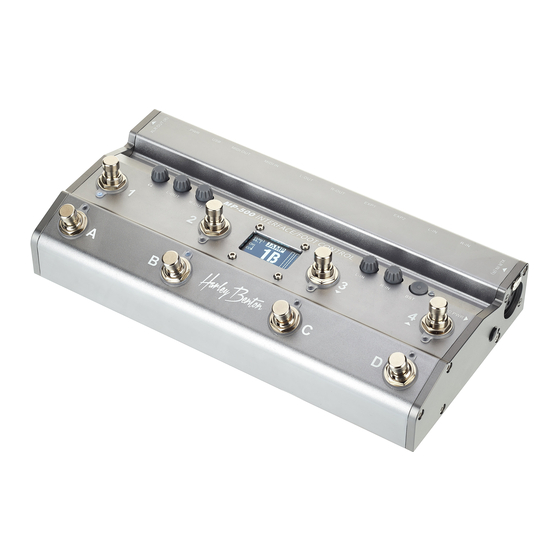
Page 14: Connections And Controls
Connections and controls Connections and controls Front panel MIDI footswitch... - Page 15 Volume control for the right input channel. Pressing the rotary knob mutes the channel. 6 [BST] Analogue boost effect for the left input channel 7 [XLR IN (R)] Input for condenser microphone or dynamic microphone, designed as XLR jack MP-500...
- Page 16 Connections and controls 8 [MIC PWR] Switch for switching on 24 V phantom power for microphones 9 [XLR OUT (R)] Outputs for the right channel, designed as XLR chassis plugs 10 Headphones output, designed as 6.35 mm jack plug 11 [1] Footswitch for sending program change and control change MIDI commands Press the footswitch, keep the footswitch pressed, and turn on the unit by connecting the USB cable to the power supply to activate the ‘JAMP’...
- Page 17 USB cable to activate the ‘ATOM’ configuration. 16 [B] Footswitch for sending program change and control change MIDI commands Press the footswitch, keep the footswitch pressed, and turn on the unit by connecting the USB cable to the power supply to activate the ‘PC-8x’ configuration. MP-500...
- Page 18 Connections and controls 17 Display 18 [C] Footswitch for sending program change and control change MIDI commands Press the footswitch, keep the footswitch pressed, and turn on the unit by connecting the USB cable to the power supply to activate the ‘CUS1’ configuration. 19 [D] Footswitch for sending program change and control change MIDI commands Press the footswitch, keep the footswitch pressed, and turn on the unit by connecting the USB cable to the power...
- Page 19 Balanced input for connecting condenser microphone or dynamic microphone, designed as 6.35 mm jack plug 21 [L-IN] Unbalanced input for connecting a guitar or dynamic microphone, designed as a 6.35mm jack plug 22 [EXP2] Input for connecting an effect pedal, designed as a 6.35 mm jack plug MP-500...
- Page 20 Connections and controls 23 [EXP1] Input for connecting an effect pedal, designed as a 6.35 mm jack plug 24 [R-OUT] Balanced output, designed as a 6.35 mm jack plug (stereo) 25 [L-OUT] Balanced output, designed as a 6.35 mm jack plug (stereo) 26 [MIDI IN] MIDI input for connecting external devices, designed as DIN connector (5-pin) 27 [MIDI OUT]...
- Page 21 33 Sub-parameter of the sent control change MIDI command (updated only if changed and held for 0.5 s) 34 Sent control change MIDI command (updated only when changed and held for 0.5 s) 35 MIDI channel used 36 Sampling rate MP-500...
-
Page 22: Operating
Operating Operating Turning the unit on Connect the device to your mobile end device using the supplied USB cable (type B). ð The device is operational. The LEDs under the push buttons light up briefly. The dis‐ play shows the current status of the device. Using a device with mobile end devices Connect the device to your mobile end device, e.g. - Page 23 ð The selected configuration is activated. The display will show the selected configura‐ tion. Foot switch Configuration Function JAMP Control of effects of the iOS software JamUp BIFX Control of effects of the Biax FX software KMPA Control of effects of the Kemper profiling amp MP-500...
- Page 24 Operating Foot switch Configuration Function AXEF Control of AXE FX effects ATOM Control of the ATOMIC amplifier effects PC-8x [1]…[4] and [A]…[D] for sending program change MIDI commands. 8 patches are a group. 8 different patches can be switched. CUS-1 Individually programmable configuration CUS-2 Individually programmable configuration...
- Page 25 ð The selected settings remain stored even after the device is turned off. Parameter Option Function ABC/123 ABC/123 Display of patch numbers 1A, 1B, 1C or 1, 2, 3 Bank Move 4x, 5x, 8x, 10x Number of selected patches in a group MP-500...
- Page 26 Operating Parameter Option Function Bank Mode WAI, IMM WAI: Switches to the first patch of the next group with a delay when the footswitch is pressed. IMM: Immediately switches to the first patch of the next group when the footswitch is pressed. SCR Start 0, 1 0: Displays the patch table starting from 0.
- Page 27 KEY 4 MOD PC#, CC# PC: Program change MIDI command CC: Control change MIDI command KEY 4 CC# 1…127 Command number of the control change MIDI command KEY 4 Tog OFF, ON ON: The sub-parameters change between 0 and 64 MP-500...
- Page 28 Operating Parameter Option Function KEY A MOD PC#, CC# PC: Program change MIDI command CC: Control change MIDI command KEY A CC# 1…127 Command number of the control change MIDI command KEY A Tog OFF, ON ON: The sub-parameters change between 0 and 64 KEY B MOD PC#, CC# PC: Program change MIDI command...
- Page 29 You can use this function to reset the device to its factory default setting. Press [L-IN] and [R-IN] simultaneously and keep both buttons pressed. Activate the device by connecting the USB cable to a mobile end device. ð The device is reset to the standard settings. MP-500...
-
Page 30: Technical Specifications
Technical specifications Technical specifications Dynamic range 108 dB -93 dB Operating supply voltage via USB Current consumption 0.15 A Phantom powering 24 V Input impedance 200 Ω Output impedance line output 100 Ω Dimensions (W × H × D) 260 mm × 60 mm × 130 mm Weight 980 g MIDI footswitch... -
Page 31: Plug And Connection Assignment
In a professional environment, therefore, the balanced transmission is preferred, because this enables an undisturbed transmission of signals over long distances. In addition to the conduc‐ tors ‘Ground’ and ‘Signal’, in a balanced transmission a second core is added. This also transfers the signal, but phase-shifted by 180°. MP-500... - Page 32 Plug and connection assignment Since the interference affects both cores equally, by subtracting the phase-shifted signals, the interfering signal is completely neutralized. The result is a pure signal without any noise inter‐ ference. 1/4" TS phone plug (mono, unbalanced) Signal Ground, shielding 1/4"...
- Page 33 Plug and connection assignment XLR plug (balanced) Ground, shielding Signal (in phase, +) Signal (out of phase, –) Shielding on plug housing (option) MP-500...
-
Page 34: Protecting The Environment
Protecting the environment Protecting the environment Disposal of the packaging mate‐ rial For the transport and protective packaging, environmentally friendly materials have been chosen that can be supplied to normal recycling. Ensure that plastic bags, packaging, etc. are properly disposed of. Do not just dispose of these materials with your normal household waste, but make sure that they are collected for recycling. - Page 36 Musikhaus Thomann · Hans-Thomann-Straße 1 · 96138 Burgebrach · Germany · www.thomann.de...
Need help?
Do you have a question about the MP-500 and is the answer not in the manual?
Questions and answers