Advertisement
Advertisement
Table of Contents

Related Manuals for Digikeijs DR5033


Summary of Contents for Digikeijs DR5033
- Page 1 DR5033 BOOSTER 3 AMP DR5033 HANDLEIDING / MANUAL BEDIENUNGSANLEITUNG / MANUEL V1.04 08-2018 © Copyright 2005 – 2018. The Netherlands. All rights reserved. No information, images or any part of this document may be copied without the prior written permission of digikeijs.
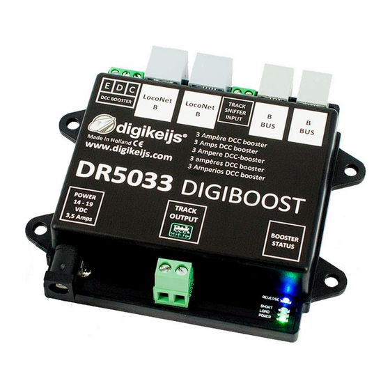
- Page 2 DR5033 BOOSTER 3 AMP CDE ingang LOCONET aansluiting B-BUS™ aansluiting CDE input LOCONET connection B-BUS™ connection CDE Eingang LOCONET Anschluss B-BUS™ Anschluss CDE entrée LOCONET connexion B-BUS™ connexion Rails sniffer Rails sniffer Rails sniffer Rails sniffer Voeding aansluiting Power connection...
-
Page 3: Beschrijving Van Het Product
The booster can be configured extremely flexibly to suit your situation using L.NET LNCV programming. When connected to L.NET, the DR5033 can optionally be switched on and off by the STOP-GO buttons on the control unit or via a (configurable) switching address. The booster then reports its status to the control unit via L.NET and the load (0-100%) and the temperature of the H-bridge can be read out in degrees C via LNCV. -
Page 4: Description Du Produit
Grâce à la programmation L.NET LNCV, le booster peut être configuré de façon extrêmement flexible afin de répondre au mieux à vos besoins. Lorsqu’il est connecté à L.NET, le DR5033 peut être allumé ou éteint par les boutons STOP-GO de l’unité centrale ou par une adresse de commutation (configurable). Le booster informe l’unité... - Page 5 • Roco Z21™ (zwart): als de z21 (wit) met als extra mogelijkheid ook de L.NET ingang van de DR5033 aan de B-BUS™ uitgang van de Z21™ aan te sluiten, waardoor de mogelijkheden van een L.NET aangesloten DR5033 beschikbaar komen én de DR5033 mid- dels het Z21-Maintenance-tool via LNCV programmering geconfigureerd en uitgelezen worden.
- Page 6 DR5033. Configuration The DR5033 is set at the factory so that all of the control units tested (Lenz™ LZV100, Roco™ MultiMaus™, Roco™ Z21™, Roco z21 ™ (white), Intellibox™, TwinCenter™ and DR5000) work out of the box. If you have a control unit that supports LNCV programming, you can configure the following on the DR5033: LNCV’s...
- Page 7 Booster können miteinander verknüpft werden (für weitere bedarf es eines Roco 'Bremsmodul'; siehe Roco™ Handbuch). • Roco™ Z21™ (schwarz): wie beim z21™ (weiß), mit der zusätzlichen Option, den L.NET Eingang des DR5033 mit dem L-Bus Aus- gang des Z21™ zu verbinden, wodurch die Merkmale eines L.NET-verbundenen DR5033 aktiviert werden und zugelassen wird, dass der DR5033 vom Z21 Wartungstool mit LNCV Programmierung konfiguriert und gelesen werden kann.
- Page 8 Roco™ Z21™ (noir) : même chose que pour le z21 (blanc), avec la possibilité supplémentaire de connecter l’entrée L.NET du DR5033 à la sortie L-Bus du Z21™, ce qui permet d’utiliser les possibilités d’un DR5033 connecté au L.NET et de configurer et lire le DR5033 par l’outil de maintenance Z21 par une programmation LNCV.
-
Page 9: Belangrijke Informatie
De L.NET ingangen zijn qua RailSync signaal (pin 1 en 6) 100% galvanisch gescheiden. Bij gebruik van een standaard L.NET kabel wordt door de L.NET infrastructuur een koppeling van de GND van Centrale en ALLE L.NET modules (dus ook de DR5033) tot stand gebracht !! Normaalgesproken levert dit geen problemen op. - Page 10 DR5033 BOOSTER 3 AMP Z21™ / z21™ Important! Z21™ does not support LocoNet-B connections TRACK SNIFFER B.BUS ™ www.digikeijs.com...
Need help?
Do you have a question about the DR5033 and is the answer not in the manual?
Questions and answers