
Subscribe to Our Youtube Channel
Related Manuals for Haws 9326


Summary of Contents for Haws 9326
- Page 1 INSTALLATION, OPERATION, AND MAINTENANCE MANUAL FOR ELECTRIC TANKLESS WATER HEATERS MODELS 9326 & 9327 0002080089, Rev 2...
- Page 3 IMPORTANT SAFETY INFORMATION READ ALL INSTRUCTIONS BEFORE USING DANGER Indicates an imminently hazardous situation which, if not avoided, will result in death or serious injury. WARNING Indicates a potentially hazardous situation which, if not avoided, could result in death or serious injury.
- Page 4 8. If the Haws 93XX unit(s) is installed in 3. The unit must be installed by a a location where water damage could licensed electrician and plumber.
- Page 5 12. Provide your heater with potable, program will be installed to establish uninterrupted supply of water at a flow before power is applied. Contact Haws Services at (800) 766-5612. constant minimum pressure of 35PSI (based on model) and maximum pressure of 150 PSI.
-
Page 7: Table Of Contents
TABLE OF CONTENTS PERFORMANCE FEATURES......................... 1 OPERATION PRINCIPLE ........................3 MOUNTING THE HEATER TO THE WALL ..................... 4 ELECTRICAL HOOKUP ........................5 PLUMBING HOOKUP ......................... 7 COMMISSIONING THE WATER HEATER .................... 10 MONITORING & PREVENTIVE MAINTENANCE .................. 14 CONTROL FEATURES ........................15 TROUBLESHOOTING PROCEDURES .................... -
Page 8: Performance Features
PERFORMANCE FEATURES Heating Technology Field Replaceable, non-ferrous, lead-free cartridge-style direct heating element Safety and Reliability Thermo-Optical sensor for protection against entrained air or improper commissioning Materials and Construction NSF-61 listed materials of construction Control and Consumption Active energy management to ensure optimal application of energy based on real-time system demands ... -
Page 10: Operation Principle
The Haws tankless water heater only uses as much power as is needed to meet the demand by fully modulating the heating elements from 0 to 100%. -
Page 11: Mounting The Heater To The Wall
MOUNTING THE HEATER TO THE WALL Please follow the mounting instructions as appropriate to your installation. Haws recommends the heater be installed close to the point of use. CAUTION This heater must be installed in a location where it is not subject to freezing temperatures, unless supplied with factory installed freeze protection Make sure the brass fittings are at the bottom of the heater. -
Page 12: Electrical Hookup
ELECTRICAL HOOKUP Haws recommends your heater be installed or serviced by a licensed plumber and electrician. WARNING Before beginning any work on this installation, BE SURE THAT THE ELECTRICAL BREAKER IS “OFF” AND THAT ALL MOUNTING AND PLUMBING WORK HAS BEEN COMPLETED PER THESE INSTRUCTIONS. - Page 13 Electrical Specifications A green terminal (or a wire connector marked “G”, “GR, “Ground”, or “GROUNDING”) is provided within the control box. To reduce the risk of electric shock, connect this terminal or connector to the grounding terminal of the electric service or supply panel with a continuous copper wire in accordance with your local electrical code.
-
Page 14: Plumbing Hookup
PLUMBING HOOKUP MUST FLUSH LINE A MINIMUM 5 MINUTES, AT A MINIMUM 15 GPM ON INITIAL START UP The heater is equipped with NPT brass fittings. Make sure ONLY NPT fittings are used for connection to this heater. Connect the cold water line with the inlet connection (RIGHT fitting) Connect the outlet pipe with the outlet fitting (LEFT fitting) - Page 15 WARNING MUST FLUSH OUT WATER HEATER FOR MINIMUM 5 MINUTES AT A MINIMUM 15 GPM ON INITIAL START UP OR AFTER ANY SERVICE WORK HAS BEEN PERFORMED. CLOSE AND OPEN DRAIN VALVE 3 TIMES TO REMOVE ANY LODGED AIR BUBBLES. FAILURE TO DO SO MAY DAMAGE THE HEATER.
- Page 16 Proper water conditions must be maintained to prevent damage to the water heater. CONSTITUENT (MG/L) MINIMUM REQUIREMENT BETTER BEST Alkalinity Calcium Carbon Dioxide Chlorine Free Chlorine 0.05 Iron 0.01 Magnesium as Mg Magnesium as Mn Nitrate Oxygen Silica Sodium Sulfate TDS* Total Hardness 6.5 –...
-
Page 17: Commissioning The Water Heater
COMMISSIONING THE WATER HEATER CAUTION BEFORE SWITCHING THE ELECTRICAL BREAKER “ON”, MAKE SURE THE INLET AND OUTLET BALL VALVES ARE FULLY OPEN AND WATER IS FLOWING THROUGH ALL POINTS OF USE FOR A MINIMUM OF 5 MINUTES AT A MINIMUM 15 GPM. Open and close drain valve 3 times while purging to remove any lodged air bubbles. - Page 18 Startup Process Plumbing Installation Checklist MUST BE FILLED OUT AND LEFT WITH WATER HEATER. MUST FLUSH WATER HEATER FOR MINIMUM 5 MINUTES AT A MINIMUM. Important - Read and fully understand all steps outlined below before proceeding. Failure to do so may damage the water heater and void any warranty.
- Page 19 Important - Read and fully understand all steps outlined below before proceeding. Failure to do so may damage the water heater and void any warranty. Technical support is available at 1 (800) 543-6163 Startup Procedure and Checklist Step Category Action Confirmed By Notes Startup...
- Page 20 Shutdown Process (Normal, Emergency, and Long Term) Shut Down Procedure Important - Read and fully understand all steps outlined below before proceeding. Failure to do so may damage the water heater and void any warranty. Technical support is available at 1 (800) 543-6163 Step Category Action...
-
Page 21: Monitoring & Preventive Maintenance
Ensure proper electrical supply as outlined within the O+M. Perform PMR per site requirements not to exceed 90 days. Maintenance inspection program: (MIP) Haws water heaters are very low maintenance. Ensure PMR is completed every 90 days. Disable power to the unit via external disconnect or local disconnects. Per site lockout procedures open cabinet door and visually inspect components for sings of damage associated with possible water leaks, excessive heat or external factors that could impact the water heater and associated components. -
Page 22: Control Features
CONTROL FEATURES CAUTION BEFORE USING THIS CONTROL, make sure all prior installation steps have been properly completed, electrical power is on and water is present in the heater. Push Button Flow Chart 1) The SETPOINT TEMP or ACTUAL TEMP screen can be SETPOINT ACTUAL selected for display as the home screen. - Page 23 8) From the LOAD PCT screen, one press of the RIGHT button LOAD PCT FLOWRATE will shift the display to the FLOWRATE screen. This shows the 0% PWR ??? GPM rate of flow of water through the heater. 9) From the FLOWRATE screen, one press of the RIGHT button will shift the display to the UNITS screen.
- Page 24 CODE1:F0 undesirable condition and will immediately shut down the operation of the heater. If faults are appearing on your heater call Haws Technical Support for assistance. Fault Codes F0: Outlet thermistor out of range F1: No change in water temperature detected...
-
Page 25: Troubleshooting Procedures
TROUBLESHOOTING PROCEDURES If you need any assistance from our Technical Service Department, make sure you can identify this water heater by having the model number and serial number. Model No. ______________________________ Serial No. ______________________________ Call (800) 766-5612 communications@hawsco.com IF TRUE IF FALSE PROBLEM POSSIBLE CAUSES... - Page 26 Verify 5VDC is present on the last optical sensor in the chain by using a Loose /cut wire to multimeter set for dc voltage at the Call Haws for support Check A17 and A18 again optical sensors connector P12 with one meter lead on the red wire and the other on the black wire.
-
Page 27: Technical Support
TECHNICAL SUPPORT TECHNICAL SUPPORT FORM PERFORM STEPS BELOW BEFORE CALLING HAWS SERVICES (800) 766-5612 WATER HEATER MODEL # ____________________________________ SERIAL # ____________________________________ Inlet Water Pressure ____________________ Inlet Water Temperature ____________________ Incoming Voltage Testing Elements L1 ____________ Amp draw on each heating element,... - Page 28 Testing Points Testing optical sensors: Ohm out optical sensors: find jack plug p5 on circuit board and place #1 lead on the blue wire, then place #2 lead on the on the blue wire on the back right optical board. Move #2 lead to each blue wire on optical boards to verify continuity.
- Page 29 Disconnect power from the heater by turning off the circuit breaker. ERROR CODES: Your heater should be installed in a NEMA 4/4X cabinet (9326/7). For units with the NEMA1 cabinet (different unit 9321), remove the 5 mounting screws to remove the cover. Plug in the USB...
- Page 30 Home screen will appear first. ACTUAL TEMP 73F The heater has recognized the USB drive USB CONN CNF file has been successfully loaded-IF “CNF ERR” is USB CONN displayed, try removing reseating the USB into the slot. CNF READ USB CONN It is now OK to turn off the power, remove the USB and replace the cover...
- Page 32 Assembly* Meter ** * HEATING ELEMENT ASSEMBLY CONSISTS OF ONE HEATER CORE AND WIRE ELEMENT(S) ** FLOW METER KIT CONSISTS OF PADDLE WHEEL, DOWEL PIN, O RING AND 4 MOUNTING SCREWS. CONTACT HAWS SERVICES AT (800) 766-5612 FOR REPAIR PARTS...
- Page 33 NEMA Cabinet 4, 4X, 4X (316) OPTIONS ARE NOT APPLICABLE TO HAWS 9321, NEMA 1 (NON- WATERPROOF) CABINET...
- Page 34 Options Optional Class 1 Division 2 Establishing Connections Sizes, Lengths & Bends Typical Single Protected Enclosure Connections Helpful Hints To ensure adequate protective gas flow to the protected enclosure(s), all piping and tubing must be fully reamed. Precautions must be taken to prevent crimping and other damage to protective gas piping and tubing. When protecting multiple enclosures with a single enclosure protection system, the enclosures must be connected in series from the smallest to the largest to ensure adequate protective gas flow.
- Page 35 Electrical Supply Requirements General Wiring Requirements Typical Enclosure Wiring Methods In a general sense, protected enclosures should be wired similar WARNING to explosion proof enclosures, in accordance with Article 500 of the National Electric Code - NFPA 70. THIS DEVICE CONTAINS ELECTRICAL PARTS Single conductor wiring should be placed in rigid metal conduit, WHICH CAN CAUSE SHOCK OR INJURY.
- Page 36 Conduit Installation Electrical Conduit WPS Style Conduit Connection Parts Choose the location for the enclosure's electrical conduit WPS & WPSA style systems provide electrical contacts for audible connection(s) based on the requirements on page 49, or visual alarm devices that signal a loss of protected enclosure "Electrical Supply Requirements".
- Page 37 Set-up Procedure Helpful Hints “Safe" pressure, for purposes of this manual, is defined To test the vent's operation, gently prod the vent flapper as a minimum .25 inch (6.4 mm) of water column. open with a soft pointed object, (example: eraser end of a pencil) ensuring that the vent valve works freely.
- Page 38 Operating Sequence WARNING Do not exceed “Safe” pressure with the Enclosure Pressure Control Valve. Operators must follow step-by-step sequence of the Start-Up Instructions Nameplate on the Protection System. Class I Purging Operation With the protective gas supply connected, enclosure power Utilizing the T-Par Valve Key supplied with system, open deenergized and alarm system energized (if utilized).
- Page 39 System Maintenance Regular Maintenance Drain the Protection System Filter (if utilized) frequently and clean system with non-solvent cleaning agents only. Long Term Maintenance Calibrate the enclosure pressure indicator to 0 inches by venting the purge pressure reference port and the protected enclosure to atmosphere and adjusting the calibration screw in the lower center portion of the indicator’s face.
- Page 40 Optional Enclosure Heater 1) Attach heat tape and foam insulation to all lengths of inlet and outlet water piping that are exposed to freezing temperature. We recommend a rating of -30 degrees F at 10 miles per hour wind. Connect the heat tape to an independent source of electrical power.
- Page 41 Optional GFCI The optional GFCI consist of (A) Control Module and (B) Current Transformer. This control module has a LCD display indicating real-time measurements. The GFCI module is preset from factory to trip at 3.0 A. Test and reset functions are carried out automatically every 24 hours.
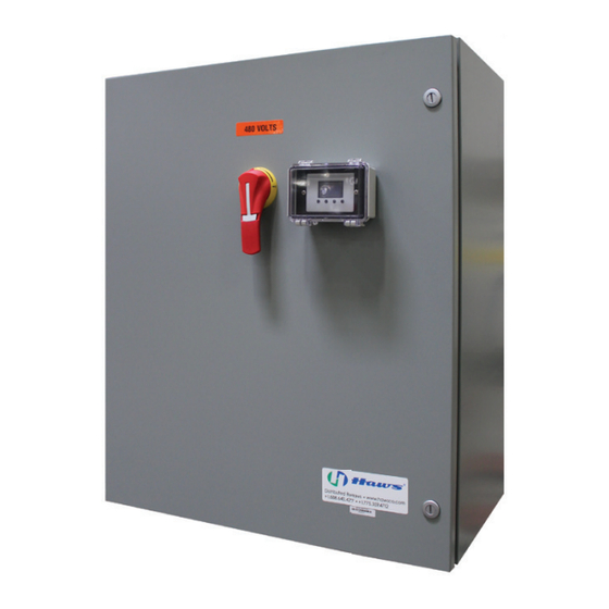
- Page 42 Optional NON-FUSIBLE Disconnect Switch DISCONNECT SWITCH MODEL 60 A 100 A 200 A Operating Voltage 600 V 600 V 600 V Max Horsepower Rating: 120 VAC 1-Phase 220/240 VAC 1-Phase 220/240 VAC 3-Phase 440/480 VAC 3-Phase 600 VAC 3=Phase Short circuit rating with fuses Branch circuit fuse type Max fuse rating (A) Disconnect Handle...
- Page 43 Optional FUSIBLE Disconnect Switch DISCONNECT SWITCH MODEL 200 AMP 100 AMP RATING (A) 200 A 100 A 600 V 600 V Max horsepower rating/ Max motor FLA current phase Three 208 v 50/150 25/78.5 240 v 60/154 30/80 480 v 125/156 60/77 600 v...
- Page 47 Where claims for defects are made, the defective part or parts shall be delivered to the Company, prepaid, for inspection. HAWS will not be liable for the cost of repairs, alterations or replacements, or for any expense connected therewith made by the owner or his agents, except upon written authority from HAWS, Sparks, Nevada.
- Page 48 Haws Corpotation 1455 Kleppe Lane, Sparks, NV 89431 (775) 359-4712 Fax: (775) 359-7424 info@hawsco.com www.hawsco.com...
Need help?
Do you have a question about the 9326 and is the answer not in the manual?
Questions and answers