Table of Contents
Advertisement
Advertisement
Table of Contents

Related Manuals for IXXAT USB-to-CAN V2

Summary of Contents for IXXAT USB-to-CAN V2
- Page 1 Hardware Manual USB-to-CAN Plugin USB CAN Interface...
- Page 2 Fax: +49 (0)7 51 / 5 61 46-29 Internet: www.hms-networks.com Support In case of unsolvable problems with this product or other IXXAT products please contact HMS in written form by: Fax: +49 (0)7 51 / 5 61 46-29 E-mail: support@ixxat.com...
-
Page 3: Table Of Contents
Inhalt Introduction ..................5 Installation ..................6 2.1 Softwareinstallation ..............6 2.2 Hardwareinstallation ............... 6 Connectors and displays .............. 7 3.1 Connectors ................7 3.1.1 USB connector ................. 7 3.1.2 Field bus connectors ..............8 3.2 Displays ................... 9 3.2.1 USB LED ................10 3.2.2 CAN LED ................ -
Page 5: Introduction
Introduction 1 Introduction By purchasing the IXXAT USB-to-CAN Plugin interface, you decided for a high-quality electronic component developed and manufactured according to the latest technological standards. In the further description these interfaces are referred as CAN interface. The features of the CAN interfaces are described below. -
Page 6: Installation
For installation of the VCI V3 driver on Windows computers, please refer to the VCI installation manual. IXXAT also offers the ECI driver for Linux and real-time operating systems for many CAN interfaces. Information on supported operating systems and inter- faces is available on the IXXAT webpage http://www.ixxat.com. -
Page 7: Connectors And Displays
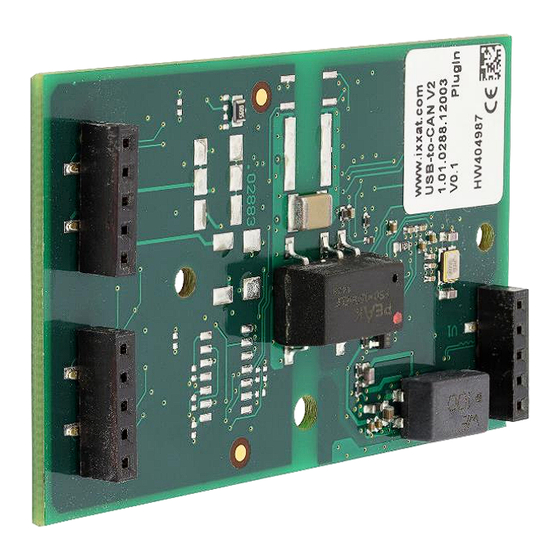
Connectors and displays 3 Connectors and displays Connectors In Figure 3-1 the position of field bus and USB connectors of the CAN Inter- face with the appropriate pin no. 1 is shown. Figure 3-1: Displays (LED) on bottom side 3.1.1 USB connector The shield (pin 5) of the USB cable is connected to ground (GND) using a 100nF capacitor and therefore also connected to ground of the USB plug. -
Page 8: Field Bus Connectors
Connectors and displays 3.1.2 Field bus connectors If you are using a not galvanic isolated CAN interface, field bus ground (CAN GND) and USB ground (GND) have the same potential. Using a CAN interface with galvanic isolation, these grounds are separated. Please be care, that in this case the grounds of the field busses (CAN1 / CAN 2 / LIN) have no galvanic isolation among each other. -
Page 9: Displays
Connectors and displays Displays The CAN interfaces have LED´s that shows the current communication status of USB and fieldbus activities (see Figure 3-2). Figure 3-2: displays (LEDs) on top side Available LEDs on the different CAN interfaces are show in Table 3-3 CAN Interface 1.01.0288.xxxxx LED Pos. -
Page 10: Usb Led
Connectors and displays 3.2.1 USB LED Light Description Causes / Hints pattern No communication via USB Device not properly initialized, maybe the USB port can´t provide enough power. Device not connected to USB port Device ready for action green USB communication pos- sible... -
Page 11: Lin Led
Connectors and displays 3.2.4 LIN LED LIN functionality is only available on model 1.01.0288.22043. Light Description Causes / Hints pattern No LIN communication on the LIN bus No LIN Device not connected LIN bus communication With each LIN message the LED is trig- green/gre LIN communication en flash... -
Page 12: Dimensions
Dimensions 4 Dimensions Figure 4-1 shows the mechanical dimensions of the CAN interface. All dimen- sions in millimeter ± 0.1 if not otherwise noted. Overview Figure 4-1: display (LEDs) on bottom side Recommended fastening elements Using the foreseen mounting holes, fastening elements shown in Table 4-1 are recommended. -
Page 13: Mounting Options
Dimensions Mounting options The CAN interface can be mounted in two ways therefore different heights are to be considered. 4.3.1 Display (LED) on bottom side Mounting the device in this orientation, the display elements (LEDs) are on the baseboard side and cannot be optimally viewed. Figure 4-3 Figure 4-2 4.3.2 Display (LED) on top side... -
Page 14: Notes
CAN Busabschluss There is no bus termination resistor for the CAN bus in the CAN interface inte- grated. IXXAT offers a bus termination resistor as a feed through connector as accessory (order number 1.04.0075.03000) Figure 5-1: CAN bus termination resistor 1.04.0075.03000 LIN interface A LIN interface is only available on model 1.01.0288.22043. -
Page 15: Appendix
Appendix 6 Appendix Technical data USB interface USB 2.0, Hi-Speed (480 MBit/s) Microcontroller / RAM / Flash: 32 Bit / 192 kByte / 512 kByte CAN High Speed , ISO 11898-2 CAN bitrates: 10 kbit/s - 1 Mbit/s CAN transceiver: TI SN65HVD251 CAN bus termination: none... -
Page 16: Support
Appendix Support For more information on our products, FAQ lists and installation tips, please refer to the support area on our homepage (http://www.ixxat.com). There you will also find information on current product versions and available updates. Returning hardware If it is necessary to return hardware to us, please download the relevant RMA form from our homepage and follow the instructions on this form. -
Page 17: Information On Emc
EC Declaration of Conformity EMC compliance testing has been conducted to the Electromagnetic Compati- bility Directive 2004/108/EC. For more information please consult the EMC compliance document on the support pages on IXXAT website.. Copyright HMS Technology USB-to-CAN -Plugin Manual, V1.2...
Need help?
Do you have a question about the USB-to-CAN V2 and is the answer not in the manual?
Questions and answers