Advertisement
Quick Links
Download this manual
See also:
Technical Manual
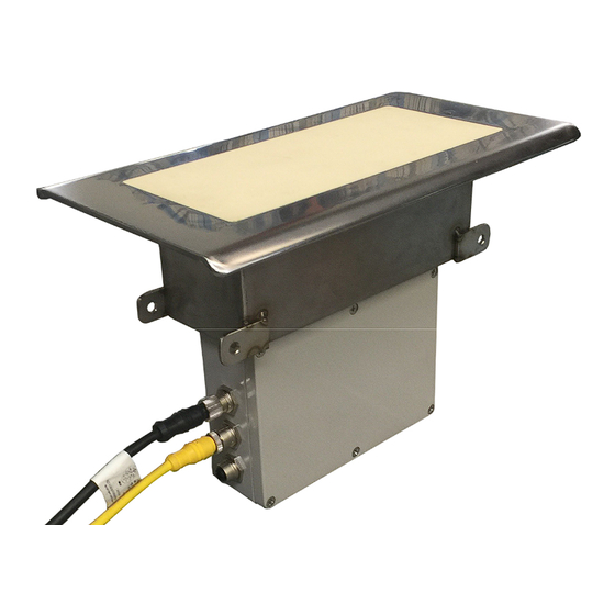
Ceramic Face Sensor
ST-3300
with Attached Sensor Electronics Unit
Installation Instructions
Sensortech Systems, Inc.
2221 E. Celsius Avenue Unit B
Oxnard, California USA 93030
805-981-3735 main
805-981-3738 fax
www.sensortech.com
© Sensortech Systems, Inc. 2016
Page 1 of 13
Rev.8-2016
Advertisement

Related Manuals for Sensortech Systems ST-3300


Summary of Contents for Sensortech Systems ST-3300
-
Page 1: Installation Instructions
Ceramic Face Sensor ST-3300 with Attached Sensor Electronics Unit Installation Instructions Sensortech Systems, Inc. 2221 E. Celsius Avenue Unit B Oxnard, California USA 93030 805-981-3735 main 805-981-3738 fax www.sensortech.com © Sensortech Systems, Inc. 2016 Page 1 of 13 Rev.8-2016... - Page 2 Ceramic Face Sensor Antenna with Attached Sensor Electronics Unit Power/Interface Option ST-3300 I/O Unit – a NEMA4 rated metal enclosure containing +/-15V DC power supply and control signals for the Ceramic Face Sensor with Attached Sensor Electronics Unit. The I/O Unit connects to the user’s A/C power and provides terminal blocks...
- Page 3 Figure 3. System Wiring Diagram © Sensortech Systems, Inc. 2016 Page 3 of 13 Rev.8-2016...
- Page 4 Figure 4. Sensor Installation Diagram © Sensortech Systems, Inc. 2016 Page 4 of 13 Rev.8-2016...
- Page 5 Figure 5. 12 x 7 inch (30.48 x 17.78cm) Ceramic Face Sensor Dimensions © Sensortech Systems, Inc. 2016 Page 5 of 13 Rev.8-2016...
- Page 6 Figure 6. Example of Mounting Saddle for Ceramic Face Sensor Installation © Sensortech Systems, Inc. 2016 Page 6 of 13 Rev.8-2016...
- Page 7 ST-3300 Ceramic Face Sensor Installation Guidelines Locating the Sensor Select a location to install the Sensor where the board product being measured will remain flat during travel over the Sensor location for the full length or width of board. Avoid locations where the contact (vertical height) between the board and Sensor may change during board travel due to changing slope or roller height change on conveyor.
- Page 8 Shim the last roller’s bearing assembly so that it is level with the first roller. Shim the remaining four rollers’ bearing assemblies so that each roller is within 0.01 inches (.25mm) of level. © Sensortech Systems, Inc. 2016 Page 8 of 13 Rev.8-2016...
- Page 9 Level Rollers Level Roller Bearing Conveyor Frame Shim Figure 7. Example of Roller Alignment © Sensortech Systems, Inc. 2016 Page 9 of 13 Rev.8-2016...
- Page 10 Mounting the I/O Unit The ST-3300 I/O Unit is typically mounted near the Sensor in a conveniently accessible location for periodic maintenance and calibration tasks. Two standard M12 cables are used to connect the Sensor Electronics Unit to the I/O Unit. The M12 cables come in standard lengths of 33 ft.
- Page 11 Figure 9. I/O Unit Terminal Board Layout © Sensortech Systems, Inc. 2016 Page 11 of 13 Rev.8-2016...
- Page 12 Users PLC/Controller RS-485 TxD+ Users RS-485 Bus A TxD- Users PLC/Controller RS-485 TxD- Safety Ground Safety Ground (90-250VAC 50-60Hz) Line / Hot Line / Hot (90-250VAC 50-60Hz) Neutral Neutral (90-250VAC 50-60Hz) © Sensortech Systems, Inc. 2016 Page 12 of 13 Rev.8-2016...
- Page 13 8. Verify connections on I/O Unit Terminal Block Connector J9 to single phase 90-250V A/C with Earth Ground. Quick ST-3300 Calibration Allow the ST-3300 System to warm-up >60 minutes to fully stabilize before calibration and use for process measurement. Pre-Zero: Wipe the ceramic face of the sensor clean with a broom or dry cloth.
Need help?
Do you have a question about the ST-3300 and is the answer not in the manual?
Questions and answers