Advertisement
Quick Links
ST-2200 Sensor
with Attached Electronics
Installation Instructions
Sensortech Systems, Inc.
2221 E. Celsius Avenue Unit B
Oxnard, California USA 93030
805-981-3735 main
805-981-3738 fax
www.sensortech.com
© Sensortech Systems, Inc. 2016
Page 1 of 16
Rev.7-2016
Advertisement

Related Manuals for Sensortech Systems ST-2200


Summary of Contents for Sensortech Systems ST-2200
-
Page 1: Installation Instructions
ST-2200 Sensor with Attached Electronics Installation Instructions Sensortech Systems, Inc. 2221 E. Celsius Avenue Unit B Oxnard, California USA 93030 805-981-3735 main 805-981-3738 fax www.sensortech.com © Sensortech Systems, Inc. 2016 Page 1 of 16 Rev.7-2016... - Page 2 ST-2200 Sensor System: The two main components in the system are: 1. ST-2200 Processor Unit (Processor) – an intelligent measurement and control unit that connects to the Sensor Electronics Unit and provides moisture measurements via serial, 4- 20mA and front panel LED display. The Processor is also referred to as the Signal Processor.
- Page 3 ST-2200 Sensor System Installation Guidelines Locating the Sensor: Select a location to install the ST-2200 Sensor where the board will remain flat over the Sensor for the full length or width of board travel over the Sensor. Avoid locations where the air gap between the board and Sensor may change during board travel due to changing slope or roller height on Dry End Transfer conveyor or Takeoff Cascade.
- Page 4 Sensor Electronics to a local Earth Ground potential. Ensure sensor frame is grounded to process frame or conveyor frame, etc. This is not a safety requirement, but may influence instrument performance. © Sensortech Systems, Inc. 2016 Page 4 of 16 Rev.7-2016...
- Page 5 Figure 3. 12-inch (30.48cm) Sensor Dimensions © Sensortech Systems, Inc. 2016 Page 5 of 16 Rev.7-2016...
- Page 6 Figure 4. 36-inch (91.44cm) Sensor Dimensions © Sensortech Systems, Inc. 2016 Page 6 of 16 Rev.7-2016...
-
Page 7: Mounting The Sensor
Sensor are at 0.25 in. (6.35mm) air gap spacing and moisture values are similar within +/- 1 are displayed when the Standardization Plate is placed covering one half at each end of the Sensor. © Sensortech Systems, Inc. 2016 Page 7 of 16 Rev.7-2016... - Page 8 Use a feeler gauge to measure the space from the top of Sensor to bottom of a board or use the ST-2200 Standardization Plate for board alignment. To make a feeler gauge for air gap alignment, cut two 12 in. (30 cm) lengths of 0.25 in. (6.35 mm) square or round rod and place on Sensor below the Standardization Plate and adjust the beam until the rods just touch the bottom of the Standardization Plate.
- Page 9 Level Rollers Level Roller Bearing Conveyor Frame Shim © Sensortech Systems, Inc. 2016 Page 9 of 16 Rev.7-2016...
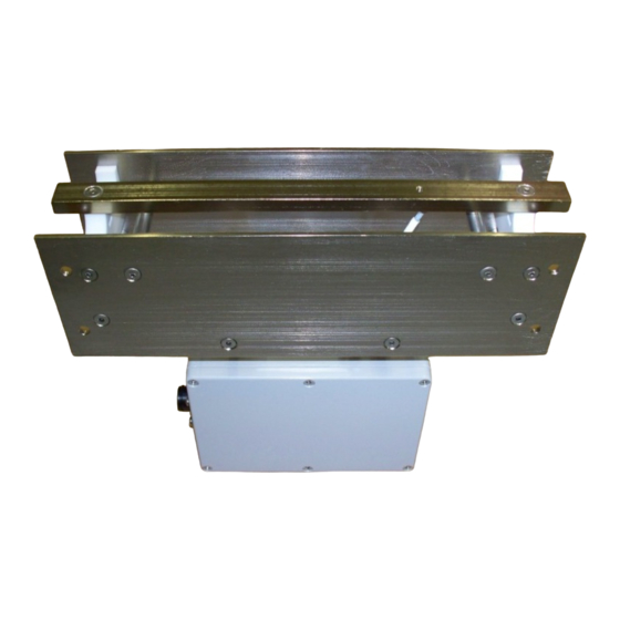
- Page 10 Figure 5. Detail of Sensor Installed on a Mounting Beam © Sensortech Systems, Inc. 2016 Page 10 of 16 Rev.7-2016...
- Page 11 Figure 6. Example of 36-inch (91.44cm) Sensor Installed on a Mounting Beam © Sensortech Systems, Inc. 2016 Page 11 of 16 Rev.7-2016...
- Page 12 Mounting the Processor Unit: The ST-2200 Processor Unit (Processor) is typically panel mounted in an enclosure next to the line for ease of access during maintenance calibration or in a control room within the Processor Cable length to the Sensor.
- Page 13 To panel mount the Processor, use the panel cut-out mounting diagram below to cut out a rectangular hole for the front panel. Drill four thru holes to install bolts to attach to the Processor mounting brackets. Figure 8. Processor Panel Cut-out Dimensions © Sensortech Systems, Inc. 2016 Page 13 of 16 Rev.7-2016...
- Page 14 ST-2200 System Power-up: Please verify the following before applying power to the ST-2200 Processor: 1. Securely tighten the black Amphenol connector located on the side of the Sensor. 2. Ensure the nine wires on the Processor Cable from the Sensor Electronics Unit are wired into the terminal block labeled SENSOR INPUT on the rear of the Processor.
- Page 15 ST-2200 PROCESSOR COMMANDS - QUICK REFERENCE Function Range Range Number High Default Description General Product code Password ****** ****** ****** Sample Rate 10ms Damping Decimal selection Pre-zero Standardization Sampling Mode Batch Average mode Void Time ATRO New Password ****** Limits Low moisture limit -5.0...
- Page 16 Dielectric pre-zero value 0.0000 Dielectric standardization value 50.00 Dielectric loss input Display Raw temperature Display Raw weight Display Raw distance Display Delta frequency Display Display test Display Keyboard test Display Software Version © Sensortech Systems, Inc. 2016 Page 16 of 16 Rev.7-2016...
Need help?
Do you have a question about the ST-2200 and is the answer not in the manual?
Questions and answers