
Related Manuals for AVI AVI-PDU Series

Summary of Contents for AVI AVI-PDU Series
-
Page 1: Installation And
Installation and Operating Instructions Series AVI-PDU RF DRIVEN SHIELD LEVEL SWITCH... - Page 2 General Safety Notes For personnel and equipment safety, please use care when lifting and installing equipment. Total weight about 5 kg or higher with certain longer cable probes and over 15 kg with flanges. Be aware of the power and relay wiring when doing calibration or maintenance as high voltage can exist on these connections.
-
Page 3: Section 1 Introduction
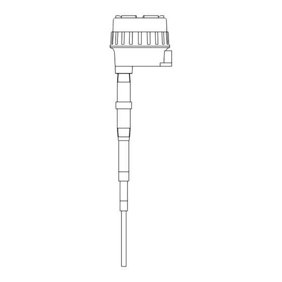
1.1 System Description This instruction manual is for the AVI-PDU Series smart two wire RF admittance level limit switch, which is used for most level measurements and control and is suitable for almost all industrial or civil applications where measuring level of liquids, powders, slurries and interface. - Page 4 inactive shield center rod material insulating 1.2 Sensing element construction Figure The RF admittance technology eliminates the effect of build-up on the sensing element (usually called coating), using a five layer coaxial configuration sensing element (See figure 1.2 sensing element in vessel). The measuring element is the center rod, Driven Shield is the middle element, and the inactive (ground) is the outside element.
-
Page 5: Section 2 Specification
SECTION 2 SPECIFICATION: 2.1 System specification: Measuring circuit terminals: measurement category II, only use the equipment for measurements within measurement category I and II, transient over voltage is 2500V. Output:DPDT reply (double pole double throw) Contact Rating:250VAC:1A inductive,3A non-inductive 30~265VAC, 50/60Hz & 21~27VDC Power requirement:Universal Power supply Power consumption:2W Resolution:0.2 pF or lower... -
Page 6: Section 3 Model Number
SECTION 3 MODEL NUMBER Probe (sensing element) specifications S.E. Mounting Probes SHD L/INACT L Wetted Insula- Weight S.E. S.E. Type S.E. Temp. Application Numbe Material tion /Anchor Mounting &Press St.500mm(19.7") 250mm(9.8")/180mm 304SS 3/4"BSPT; OD 9mm(0.35") 100℃/1.0MPa Normal temp. (212℉/145psi) /250mm(9.8") (7");... -
Page 7: Section 4 Installation
4.2 General requirements The AVI-PDU series level system can be mounted vertically, horizontally or at an angle. Be certain that neither the measuring element nor the driven shield element contact the vessel wall, nozzle or any obstruction in the vessel. - Page 8 4.3 Integral Installation The AVI-PDU series level switch is designed and suitable for most industrial applications. The mounting location of the electronic unit should free of vibration, corrosive atmospheres, or any possibility of mechanical damage for maximum service life. If this is not possible, consider a remote electronic system. Most integral systems can be field converted to remote electronic system.
- Page 9 4.5 Sensing Element Installation When selecting an installation point, be sure the measuring element will contact the material at the point the alarm should be initiated. Do not install directly under a flow stream or feed line. Be aware of the angle of repose in granular bins and silos, the level must reach the probe.
- Page 10 Anchor mounting Bent mounting Bracket mounting in open vessel External side arm mounting...
- Page 11 15° Different Mounting Angle Flushing Mounting Silo Application...
- Page 12 4.7 System wiring None hazard area Hazard area Ex tube Ex tube Relay output Power supply Ex tube Relay Power supply output line inlet line Figure 4.4 System wiring 4.8 Sensing Element wiring Assure power to the equipment has been turned off before opening the explosion-proof housing.
- Page 13 Figure 4.6 Remote System wiring 4.9 Relay wiring Assure power to the equipment has been turned off before opening the explosion-proof housing. Also make sure relay power has been turned off over ten minutes! !Be sure all power and relay wires do NOT have power! The section area of wires should between 0.13-2.1mm (AWG14-26),insulation rating over 1500V.
-
Page 14: Section 5 Function Setting
4.7 relay contacts 4.8 contact position in normal status 4.10 Power wiring Assure power to the equipment has been turned off before opening the explosion-proof housing. Also make sure relay power has been turned off over ten minutes!! The cross section area of wires should be between 0.13-2.1mm (AWG14-26) ,insulation rating over 1500V. - Page 15 High alarm Low alarm Figure 5.1 HLFS/LLFS 5.3 Time delay setting The time delay adjustment is a potentiometer located on the top of the unit “TIME DELAY”. It could adjust the reset time of the relay when an alarm condition ceases to exist. Clockwise the adjustment could increasing the time delay.
-
Page 16: Section 6 Calibration
6.1 Start Up The AVI-PDU is ready for operation when the system is installed and wired in accordance with previous instructions. The area should be evaluated, and if found safe, the housing cover should be removed for start-up. It is advisable at this time to disable control elements until proper operation is verified. - Page 17 SECTION 7 TROUBLESHOOTING 7.1 Introduction AVI-PDU series is a solid-state device with no moving parts except the alarm relay. Neither the probe nor the electronics require routine maintenance or periodic adjustments. All components are tested and inspected during manufacture and then as a complete system. The systems are designed to give years of unattended service.
- Page 18 7.3 Testing the sensing element A. See figure 7.1. Disconnect the sensing element wires from the instrument by removing the blue wire from the center terminal and the red wire from shield terminal. B. See figure 7.2. Using an analog ohmmeter, measuring the following values •...
- Page 19 blue blue green green blue blue 7.3 Integral cable 7.4 Remote cable Remote Cable Resistance between the two blue spade lugs( < 10Ω) Resistance between the two red spade lugs( < 10Ω) Resistance between the two green spade lugs( < 10Ω) Resistance between the three different color lugs(...
Need help?
Do you have a question about the AVI-PDU Series and is the answer not in the manual?
Questions and answers