Advertisement
Available languages
Available languages
Quick Links
Advertisement

Related Manuals for Doosan Governor DGC-2013


Summary of Contents for Doosan Governor DGC-2013
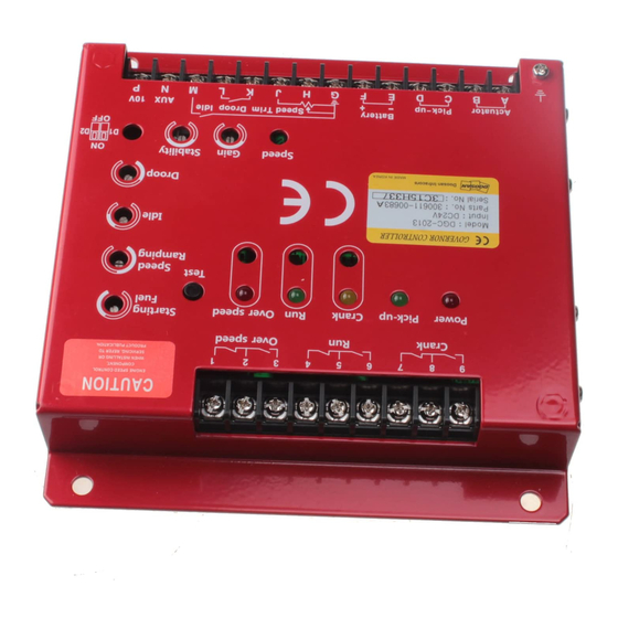
- Page 1 September 2013 Ver. 1.00 DGC-2013 Governor Controller Unit Owner's Manual...
- Page 2 Crank Over speed � � � Power Pick-up Crank Over speed Starting ➍ Fuel Test Speed ➎ Ramping � ➓ ➒ ➏ Idle ➐ Droop ➊ ➋ ➌ Speed Gain Stability Idle Battery Speed Trim Droop ➑ 접지 Actuator Pick-up AUX 10V 볼트...
- Page 3 컨트롤러 설치(장착) 및 주의사항 물이나 습기로부터의 피해에 대비하여 제어반의 벽면에 수직으로 장착하고, 기기 주변에 발열체의 ● 열이 전달되지 않도록 주의한다. 또한 장기간(1개월 이상 또는 결로현상 발생시) 습도에 노출 시에는 노출된 습기로 인하여 내부 회로의 저항값의 변동이 발생되어 정격 회전수에 도달하지 못할 수...
- Page 4 조정(튜닝) 순서 및 방법 ▹ CASE 전면 가변저항의 Guide range는 두산인프라코어(주) 엔진에 적용시 조정 범위임. (-)자형 미세 드라이버 ▹ 가변저항 조정 공구는 크기에 맞는 를 사용하시오.(저항 파손 주의) ▹ 엔진 기동전에 모든 외부기기의 결선 상태가 정확한지 점검하시오. ▶엔진 시동 특성 조정 1.
- Page 5 ▶가버너 특성 조정 7. G-M 단자 연결 해제 초기속도 (스위치 OFF)후, 엔진이 가동속도 (RUN Speed)에 도달 상태에서 조정. 8. 게인(Gain)조정. •무부하 상태에서 엔진이 불안정해질 때까지 ➋ Gain 가변저항을 시계 방향( )으로 돌린다. •➋ Gain 가변저항을 반시계방향( )으로 서서히 돌리면서 RPM이 가장...
- Page 6 ▶ Starting Fuel 조정 (배기가스 최소화하는 방법) •초기속도 스위치 ON→초기속도를 800RPM에 조정→엔진의 속도가 떨어질 때까지 ➍ Starting Fuel 가변저항을 반시계 방향( )으로 돌린다.→안정성을 위해 다시 시계 방향 ( )으로 15° 정도 더 돌린다. ◈ 엔진 기동시에 매연이 심하지 않으면, ➍ Starting Fuel 조정은 5시 방향에서 높게 설정할 것을 권한다. 너무...
- Page 7 ➍ Speed Speed ➎ Ramping Ramping � ➓ ➒ ➏ Idle Idle ➐ Droop Droop Speed Speed Gain Gain Stability Idle Idle Battery Battery Speed Trim Droop Speed Trim Droop 접지 접지 ➑ Actuator Actuator Pick-up Pick-up AUX 10V AUX 10V 볼트...
- Page 8 외부 결선 ▹ 『그림2.』의 결선도를 참조하여 연결한다. ▹ 모든 배선은 규정된 1.5㎟ 이상의 전선을 사용하고, 실드 전선을 사용한다. ▹ 실드 전선을 사용시 『그림2』에서 표기되지 않은 모든 실드선은 반드시 프레임 접지시켜야 한다. ① 액튜에이터의 배선은 TWIST된 케이블을 사용해야 된다. 결선 후, A-B간 저항값은 3.5Ω~4.5Ω 이어야...
- Page 9 ▶마그네틱 속도 센서 장착 및 연결 •마그네틱 속도 센서와 링 기어 사이의 최적 간격은 0.45mm 정도이다. 이렇게 하려면 센서를 링 기어에 닿을 때까지 조인 후, 이를 다시 역방향으로 3/4회전 돌리면 적당한 간격을 얻을 수 있다. •속도센서 신호는 운전 상태에서 단자 간...
- Page 10 품 번 300611-00683 300611-00684 300611-00685 300611-00686 1725rpm 2070rpm 1725rpm 2070rpm Overspeed (기어잇수 160개기준) (기어잇수 160개기준) (기어잇수 152개기준) (기어잇수 152개기준) Run lamp Maximum *CW Maximum CW Maximum CW Maximum CW Crank lamp Maximum CW Maximum CW Maximum CW Maximum CW Mid-range Mid-range Mid-range Mid-range...
- Page 11 •DROOP의 응용 : DROOP운전을 위해서는 단자에 연결된 드룹 선택 스위치를 ON 시킨다. ➐ Droop 2. DROOP 모드에서는 부하의 증가에 따라 속도는 감속되는데, " " 조정 가변저항을 이용하여 DROOP의 양(%)을 결정 할 수 있다. 시계 방향으로 돌릴수록 감속 폭은 커진다. (DROOP 양(%) 증가) •일반적으로...
- Page 12 시스템 고장진단 불안정성(Instability) ▶ 빠른 주기의 불안정성(Hunting) SW D1 및 D2 의 응용 (그림1. 참조) D1을 위치에 놓으면 미분기능이 동작 된다. ● 속도(rpm) 변화에 대한 응답성을 높일 수 있어 속도 변화에 대한 빠른 대응이 가능하다. ● 외부 고주파 Noise에도 민감하게 반응하여 빠른 주기의 미세한 헌팅이 발생될 수 있다. ●...
- Page 13 시스템의 미동작시 엔진 가버너 시스템이 정상 동작되지 않는 경우, 아래 표에 기술된 내용으로 테스트를 하면 원인을 추정할 수 있다. 여기서 (+), (-)는 측정기의 극성이다. 아래 표의 방법으로 테스트의 결과가 정상이면 액츄에이터나 액츄에이터 결선 불량일 가능성이 있으므로 액츄에이터를 점검하라. 단계 측정단자 측정시기...
- Page 15 September 2013 Ver. 1.00 DGC-2013 Governor Controller Unit Owner's Manual SALE : DOOSAN A/S CENTER 82-31-400-2114 A/S : ENGINE TECH' SERVICE DIV. 82-32-211-1114...
- Page 16 Crank Over speed � � � Power Pick-up Crank Over speed Starting ➍ Fuel Test Speed ➎ Ramping � ➓ ➒ ➏ Idle ➐ Droop ➊ ➋ ➌ Speed Gain Stability Idle Battery Speed Trim Droop ➑ Grounding Grounding Actuator Pick-up AUX 10V Bolt...
-
Page 17: Mounting & Warning
Mounting & Warning • Mount the controller unit vertically to the surface of a control cabinet to protect from water and high humidity, and do not expose the controller unit to the source of radiant heat. In the case of extended exposure to humidity (for over a month or condensation problem), dry the controller unit thoroughly before using as the number of rated turn could not be reached from fluctuation in the resistance value of internal circuit resulting from humidity. - Page 18 ▹ The guide range of potentiometer resistance ▹ Adjustment range for potentiometer in front of CASE is the adjustment range for application to Doosan Infracore engine. ▹ For potentiometer adjustment, use a small size (-) screw driver. (beware of potentiometer damage) ▹...
- Page 19 ◈ It should not be overlooked that idle speed is one of important factors that determine engine start-up characteristics. Accordingly, it is necessary to adjust the idle speed after adjusting rated speed regardless of the use of "idle mode". Governor Characteristic Adjustment ▶...
- Page 20 12. Adjust Overspeed Lamp ON time. • At the rate speed, while pressing Test button ( ), slowly turn ➒ Over Speed potentiometer counterclockwise ( ) until Overspeed Lamp is turned on and the engine shuts off. • With the above adjustment, the overspeed function is set at about 15% higher speed. ※...
- Page 21 ➍ Speed Speed ➎ Ramping Ramping � ➓ ➒ ➏ Idle Idle ➐ Droop Droop Speed Speed Gain Gain Stability Idle Idle Battery Battery Speed Trim Droop Speed Trim Droop 접지 Grounding ➑ Actuator Actuator Pick-up Pick-up AUX 10V AUX 10V Bolt 볼트...
-
Page 22: External Wiring
External Wiring ▹ Refer to [Fig. 2] Wiring Diagram for wiring. ▹ For every wiring, use 1.5㎟ or larger shielded cable. ▹ While using shielded cable, every shielded cable not displayed in [Fig. 2] must be grounded to the frame. ①... - Page 23 Magnetic Speed Sensor Installation & Connection ▶ • The optimal distance between magnetic speed sensor and ring gear is about 0.45mm. Accordingly, after tightening sensor until it touches the ring gear, turn this in reverse direction by 3/4 for appropriate distance. •...
- Page 24 300611-00683 300611-00684 300611-00685 300611-00686 1725rpm 2070rpm 1725rpm 2070rpm Overspeed (based on 160 gear teeth) (based on 160 gear teeth) (based on 152 gear teeth) (based on 152 gear teeth) Run lamp Maximum *CW Maximum CW Maximum CW Maximum CW Crank lamp Maximum CW Maximum CW Maximum CW...
- Page 25 • Application of DROOP : For DROOP operation, 1. Turn ON the Droop selector switch connected to K-L terminal. 2. In DROOP mode, speed decreases as load increases, and DROOP amount (%) can be determined by using "➐Droop" adjustment potentiometer. The range of decrease increases when turned in clockwise direction.
- Page 26 System Troubleshooting Instability Fast Cycle Instability (Hunting) ▶ * Application of SW D1 & D2 (Refer to Fig. 1) • Placing D1 at ON position will operated differential function. • Quick response to speed change is possible by increasing the responsiveness to speed changes in speed (rpm).
- Page 27 System Inoperative When the engine governor system does not operated normally, its cause can be estimated by testing based on the contents described below. (+), (-) refer to the polarity of measuring instrument. If the result of test conducted through below methods is normal, the cause might be defective actuator or actuator wiring.
- Page 29 September 2013 Ver. 1.00 DGC-2013 Governor Controller Unit Owner's Manual SALE : DOOSAN A/S CENTER 82-31-400-2114 A/S : ENGINE TECH' SERVICE DIV. 82-32-211-1114...
- Page 30 Crank Over speed � � � Power Pick-up Crank Over speed Starting ➍ Fuel Test Speed ➎ Ramping � ➓ ➒ ➏ Idle ➐ Droop ➊ ➋ ➌ Speed Gain Stability Idle Battery Speed Trim Droop 框架 ➑ Actuator Pick-up AUX 10V 接地楼拴...
- Page 31 项 controller 安设(安装) 及注意事 防止受到水或湿气影响, 安装时注意安装方向, 得控制板墙壁的垂直方向. 还要注意机 ● 器周围没有发热体. 如果长时间(1个月以上)与湿气接触时, 会发生内部电路电阻额的 变动而不能达到额定转速, 使用前充分干燥后使用。 防止超速, 不要只依靠子调速器(governor)的ACTUATOR, 推荐安装使用独立的发动机 ● 停止装置, 比如说燃料切断电子阀(solenoid) 各调整电阻设定表示为发动机平均设定范围, 推荐使用发动机运用在设定范围内 ● EMC (Electromagnetic Compatability) ● Controller受到电子波影响最少化, controller安装在金属, 该金属接地. 或者使用有保护 (shield)的金属箱和shield线, 所有的shield线在一个地方接地。 假如不履行上述的电子波防止安设方法而发生的EMC有关产品品质问题, 不能保证。 调 说 整 mode 明 >> <<...
- Page 32 调 整 顺 序和方法 ▹ CASE 前面可变电阻上 Guide range为斗山发动机适用的调整范围 ▹ 可变电阻调整工具,请使用大小合适的一字螺丝刀 (注意电阻破损) ▹ 发动机启动前,检验所有的外部机器结线状况 调 整 ▶发动机启动特性 1. G-M 端头 连接 (发动机 初期速度(Idle) 开关(switch) ON). Starting ➍ Fuel 2. ➍ Starting Fuel Speed ➎ • 调整目的 : 按照发动机状况, 调整最经济油耗。 Ramping •推荐方向...
- Page 33 调 调 速器(governor)特性 整 ▶ 7. 拆卸G-M 端头连接(初期速度开关(switch)OFF)后, 达到发动机启动速度(RUN Speed)后调整. 8. (Gain)调整. • 在无负荷状况, ➋ Gain 可变电阻往顺时针 方向( )调, 跳到发动机不 稳定 • ➋ Gain可变电阻往逆时针方向( )慢慢调, 调为RPM最稳定的位置。 • 为了稳定性强化, ➋ Gain 可变电阻往逆时针方向调20分 (10°) 9. (Stability) 调整. •在无负荷状况, 把 ➋ Stability可变电阻,往顺时针方向( )调整,跳到发动机不稳定 •...
- Page 34 Starting Fuel 调整 (排气最少化方法) ▶ Starting 初期速度 开关(switch) ON → 初期速度调800RPM → 发动机速度减少为止把 ➍ • Fuel 可变电阻往逆时针 方向 调→ 为了稳定性增加,往顺时针方向 再调15° ◈ 发动机启动时烟度不是不好的话, ➍ Starting 调整推荐5点方向, 稍为高点, 如果台地的话, 启动不好, 启动后 会发生Overshoot 现象, 会超过发动机超速度设定指 启动不行的情况 ▶ 线路结线没有异常 → 所有的调整指数调为 "出库时调整指数" • (图2.
- Page 35 ➍ Speed Speed ➎ Ramping Ramping � ➓ ➒ ➏ Idle Idle ➐ Droop Droop Speed Speed Gain Gain Stability Idle Idle Battery Battery Speed Trim Droop Speed Trim Droop 접지 ➑ Actuator Actuator Pick-up Pick-up 框架 AUX 10V AUX 10V 볼트...
- Page 36 结线 外部 ▹『图2.』参见结线图连接 ▹ 所有线路要使用规定的1.5㎟ 以上的shield 电线. ▹ 使用时『图2』上没有的shield 电线一定要进行接地措施。 ① actuator 线路得使用 TWIST cable, 结线后, A-B 电阻 3.5~4.5Ω ② 磁速度 sensor的 cable 必须使用Shield 电线, shield 部位已定连接于端头 D这shield 部位如果与 发动机接地,或未征产接地的话,歪曲的速度信号输入进取,会发生发动机hunting等的问 题。 ③ 端头 E 和 F 连接,注意电池(battery)极性 Battery(+)面和端头 F 中间安设10A 保险丝(fuse) 连接后,端头间电压确认...
- Page 37 磁速度 sensor 安装及连接 ▶ 磁速度 sensor和 ring gear 之间的理想间隙为 0.45mm. • 把sensor组装到ring gear 接触, 然后往后方向逆转3/4, 可以得到适当的间隙. 在运转 状况, 速度sensor 信号 端头 C-D间 电压(AC) 测定而确认. • controller sensor 电压为 AC 3V 以上 • 调 整 外部 速度 与『图3.』一样, 外部 连接速度 调整 可变电阻器, 可以在特定速度 范围, 在外部 remote 调整 发动机速度, 参考表1, 在要求速度范围, 设定电阻值...
- Page 38 300611-00683 300611-00684 300611-00685 300611-00686 Overspeed 1725rpm (160齿) 2070rpm (160齿) 1725rpm (152齿) 2070rpm (152齿) Run lamp Maximum *CW Maximum CW Maximum CW Maximum CW Crank lamp Maximum CW Maximum CW Maximum CW Maximum CW Mid-range Mid-range Mid-range Mid-range Gain (12点 方向) (12点...
- Page 39 • DROOP 使用 1. 与K-L端头连接的 droop选择 开关(switch) ON 2. DROOP mode时, 负荷增加而速度减速,利用 " ➐ Droop" 调整 可变电阻可以调整 DROOP量(%). 顺时针方向, 减速量多 (DROOP(%) 增加) • 一般使用的 DROOP量是 10% 以内, speed DROOP 调速器(governor) 稳定性 维持所要求的 最少 DROOP量为 2.5% 以上。 DROOP 调整量会引起已经设定完毕的额定速度的变化, 发动机速度确认后, 必要时从新调 整速度。...
- Page 40 诊断 系统故障 不稳定性(Instability) 短频波的 不稳定性( Hunting ) ▶ * SW D1及 D2的应用 (参考图1) D1选 ON, 开始启动 微分功能 ● 可以提高速度(rpm) 变化的反应性, 可以速度变化快速对应. ● 外部 高频 Noise 会发生 短频波的 稍微hunting. ● 这时候, D1 OFF, 从新调整 ➋ Gain 及 ➌ Stability 还是不稳定现象没有消灭, 机器 SW D2 OFF 会有些帮助 发动机稳定化 ●...
- Page 41 系统(system)异常动作 发动机 调速器(governor)系统(system)异常动作, 参看下图测试能推定原因. 如下方法测试结果正 常的话,很可能是 actuator 或 actuator 接线不良。 序 测定端头 测定 正常时 异常时推定原因 措施事项 F(+) & E(-) DC 24V 1. 电池异常 1. 电池接线 停止 2. 结线不良 2. 电池更换 F(+) & E(-) 启动器启动 DC 15以上 1. 速度 sensor 异常 1.
- Page 44 구입문의 안산부품센터 031)400-2114 A/S 문의 엔진기술서비스팀 032)211-1114...
Need help?
Do you have a question about the Governor DGC-2013 and is the answer not in the manual?
Questions and answers