Table of Contents
Advertisement
Reclosers
Form 6 Recloser Control Disassembly,
Reassembly, and Testing Instructions
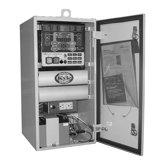
Figure 1.
®
Kyle
Form 6 Pole Mount, Yard Mount, and Rack Mount recloser controls.
Contents
Safety Information ..................................................... 2
Hazard Statement Definitions ................................ 2
Safety Instructions .................................................. 2
Product Information .................................................. 3
Introduction ............................................................ 3
ANSI Standards ..................................................... 3
Quality Standards ................................................... 3
Acceptance and Initial Inspection .......................... 3
Handling and Storage ............................................ 3
Description ............................................................. 3
Disassembly .............................................................. 4
Disassembly Instructions ....................................... 4
Open the Module ................................................... 5
Remove/Replace CPU Board ................................ 5
Remove/Replace Comms. Accsy. Board Only ....... 6
Remove/Replace I/O Board ................................... 7
Remove/Replace Analog Board ............................. 8
August 2005 • Supersedes 6/04
Printed in USA
S280-70-11
Reassembly ............................................................... 8
Reassembly Instructions ........................................ 8
Place Module in Control ......................................... 8
Before Placing the Control Into Service ................. 9
Installation ................................................................. 9
Initial Programming Prior to Installation ................. 9
Testing ........................................................................10
Testing Instructions ................................................10
Communication Ports .............................................10
Contact Inputs/Outputs ..........................................10
Testing with Type MET Tester ................................11
Additional Information ..............................................12
Replacement Kits ...................................................12
Factory-Authorized Service Centers ......................12
Service Information
1
1
Advertisement
Table of Contents

Related Manuals for Cooper Kyle Form 6

Summary of Contents for Cooper Kyle Form 6
-
Page 1: Table Of Contents
Reclosers Service Information S280-70-11 Form 6 Recloser Control Disassembly, Reassembly, and Testing Instructions Figure 1. ® Kyle Form 6 Pole Mount, Yard Mount, and Rack Mount recloser controls. Contents Safety Information ............. 2 Reassembly ............... 8 Hazard Statement Definitions ........ 2 Reassembly Instructions ........ -
Page 2: Safety Information
FOR LIFE FOR LIFE Cooper Power Systems products meet or exceed all applicable industry standards relating to product safety. We actively promote safe practices in the use and maintenance of our products through our service literature, instructional training programs, and the continuous efforts of all Cooper Power Systems employees involved in product design, manufacture, marketing, and service. -
Page 3: Product Information
For additional information, contact your Cooper Power • Service Information S280-70-1 Form 6 Rack Mount Systems sales representative. Recloser... -
Page 4: Disassembly
Form 6 Recloser Control Disassembly, Reassembly, and Testing Instructions DISASSEMBLY Form 6 Recloser Control This step applies to Form 6 Pole and Yard mount controls. Disassembly Instructions 3. Remove module from cabinet as applicable. A. For complete scheme structure and verification These instructions describe the disassembly of the Form refer to appropriate instructions: 6 recloser control. -
Page 5: Open The Module
S280-70-11 SAFETY FOR LIFE Open the Module 4. Proceed as appropriate for kit contents: • If mounting plate is included with the kit proceed to 1. Discharge internal capacitors using a 10 ohm (5 watt) step 5. load across TB6-1 and TB6-7 for five seconds. •... -
Page 6: Remove/Replace Comms. Accsy. Board Only
Internal view of the Form 6 pole mount recloser control module. Removal/Replacement of Additional accessories are being continuously devel- oped. Contact your Cooper Power Systems representa- Communications Accessory Board Only tive for the latest information regarding particular media The Form 6 control is equipped with a Communication and communication protocol support. -
Page 7: Remove/Replace I/O Board
S280-70-11 SAFETY FOR LIFE 7. Slide mounting plate into card guide and carefully Removal/Replacement of I/O Board push the assembly into the module. 1. Remove the I/O circuit board. Refer to Form 6 Recloser Control Disassembly Instructions section. IMPORTANT: Do not damage the capacitor or any 2. -
Page 8: Remove/Replace Analog Board
Form 6 Recloser Control Disassembly, Reassembly, and Testing Instructions Removal/Replacement of Analog Board REASSEMBLY 1. Remove the analog circuit board. Refer to Form 6 Recloser Control Disassembly Instructions section. Form 6 Recloser Control 2. Remove the bottom two screws on the outside of the Reassembly Instructions right panel, left panel, and back plate of the module. -
Page 9: Before Placing The Control Into Service
S280-70-11 SAFETY FOR LIFE Before Placing the Recloser Control INSTALLATION into Service CAUTION: Equipment misoperation. Do not CAUTION: Equipment misoperation. Do not connect this control to an energized recloser until connect this control to an energized recloser until all control settings have been properly programmed all control settings have been properly programmed and verified. -
Page 10: Testing
Form 6 Recloser Control Disassembly, Reassembly, and Testing Instructions TESTING Form 6 Recloser Control Testing For information on testing refer to the appro priate instructions: Instructions • Service Information S280-70-1 Form 6 Rack Mount These instructions describe the testing of the Form 6 Control Installation and Operation Instructions recloser control. -
Page 11: Testing With Type Met Tester
S280-70-11 SAFETY FOR LIFE Testing with Type MET Tester TABLE 3 Operating Voltage Requirements for Standard and Use the Kyle ® Type MET electronic recloser control tester Optional Supervisory Inputs for Form 6 Rack and (Figure 10) to test the following functions of the Form 6 Yard Mount Recloser Controls recloser control: Module... -
Page 12: Additional Information
KA2048-637 Rev: 01 1045 Hickory Street ©2005 Cooper Power Systems or its affiliates. ® Kyle is a registered trademark of Cooper Power Systems or its affiliates. Pewaukee, WI 53072 ProView is a trademark of Cooper Power Systems or its affiliates. www.cooperpower.com...
Need help?
Do you have a question about the Kyle Form 6 and is the answer not in the manual?
Questions and answers