Table of Contents
Advertisement
IMPORTANT: PLEASE READ THESE INSTRUCTIONS CAREFULLY TO ENSURE THE
SAFE AND EFFECTIVE USE OF THIS PRODUCT.
INSTRUCTIONS
These instructions accompanying the product are the original instructions. This document is part of the product,
keep it for the life of the product passing it on to any subsequent holder of the product. Read all these
instructions before assembling, operating or maintaining this product.
This manual has been compiled by Draper Tools describing the purpose for which the product has been
designed, and contains all the necessary information to ensure its correct and safe use. By following all the
general safety instructions contained in this manual, it will ensure both product and operator safety, together
with longer life of the product itself.
AlI photographs and drawings in this manual are supplied by Draper Tools to help illustrate the operation of the
product.
Whilst every effort has been made to ensure the accuracy of information contained in this manual, the Draper
Tools policy of continuous improvement determines the right to make modifications without prior warning.
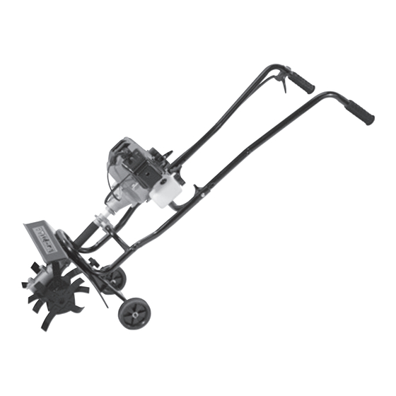
PETROL
CULTIVATOR/
TILLER
32329
Advertisement
Table of Contents
Troubleshooting

Subscribe to Our Youtube Channel
Related Manuals for Draper 32329


Summary of Contents for Draper 32329
- Page 1 AlI photographs and drawings in this manual are supplied by Draper Tools to help illustrate the operation of the product.
-
Page 2: Introduction
Commercial copying, redistribution, hiring or lending is prohibited. No part of this publication may be stored in a retrieval system or transmitted in any other form or means without written permission from Draper Tools Limited. In all cases this copyright notice must remain intact. -
Page 3: Table Of Contents
CONTENTS 1. TITLE PAGE 1.1 INTRODUCTION......................2 1.2 REVISION HISTORY ....................2 1.3 UNDERSTANDING THIS MANUAL ................2 1.4 COPYRIGHT NOTICE ....................2 2. CONTENTS 2.1 CONTENTS ........................3 3. GUARANTEE 3.1 GUARANTEE ....................... 4 4. INTRODUCTION 4.1 SCOPE......................... 5 4.2 SPECIFICATION ...................... -
Page 4: Guarantee
This guarantee applies in lieu of any other guarantee expressed or implied and variations of its terms are not authorised. Your Draper guarantee is not effective unless you can produce upon request a dated receipt or invoice to verify your proof of purchase within the guarantee period. -
Page 5: Introduction
This 2-stroke petrol cultivator/tiller is designed to prepare the ground for the planting of flowers and vegetables. Any other application is considered mis-use. 4.2 SPECIFICATION Stock No: ..........................32329 Part No: ..........................MT254 Engine displacement ......................42.7cc Maximum engine performance ....................1200W Engine idle speed (no load).................... -
Page 6: Health And Safety Information
– Maintenance and troubleshooting must be limited to the procedures described in these instructions for use. All other types of servicing must be conducted by an authorised Draper service technician. –... -
Page 7: Health And Safety Information Concerning The Use Of Fuels
HEALTH AND SAFETY INFORMATION 5.2 HEALTH AND SAFETY INFORMATION CONCERNING THE USE OF FUELS Fuels are inflammable and explosive. Reduce the risk of explosion and fire by: – Turning off and cooling the motor down before filling the tank with fuel. –... -
Page 8: Technical Description
TECHNICAL DESCRIPTION 6.1 IDENTIFICATION Start/stop. Throttle. Pull starter Exhaust. Fuel tank. Fuel filler cap. Rotavating blades × 4. Transport wheel × 2. Air filter cover. Ignition cable plug. Steering handle. Guard. Transport wheel axle fittings/adjusters - 8 -... -
Page 9: Unpacking And Checking
Lay the contents out and check them against the parts shown below. If any part is damaged or missing; please contact the Draper Helpline (the telephone number appears on the Title page) and do not attempt to use the machine. -
Page 10: Assembling The Cultivator/Tiller
ASSEMBLING THE CULTIVATOR/TILLER 8.1 FITTING THE ROTAVATING BLADES – FIGS. 1 – 4 Note: Some aspects of assembling this machine may require the need for two people. The rotavating blades are stamped L or R to identify their position on each side of the gearbox when facing the front of the machine. -
Page 11: Fitting The Wheel Bracket Assembly And Transport Wheels
ASSEMBLING THE CULTIVATOR/TILLER 8.2 FITTING THE WHEEL BRACKET ASSEMBLY AND TRANSPORT WHEELS – FIGS. 5 – 8 Place the wheel bracket assembly on the underside of the tine guard Make sure the square shoulder of the fixing bolts are pushed through the slotted holes in the wheel bracket. -
Page 12: Fitting The Handle Bars
ASSEMBLING THE CULTIVATOR/TILLER 8.3 FITTING THE HANDLE BARS – Fig.9 FIGS. 9 – 10 Slide the steering handle bars section into the supporting struts of the engine section Secure together using the 2 handle bar fixing bolts Fig.10 8.4 FITTING THE THROTTLE AND Fig.11 CABLE ASSEMBLY –... -
Page 13: Fuelling
ASSEMBLING THE CULTIVATOR/TILLER 8.5 FILLING/CHECKING Fig.13 GEARBOX OIL – FIG. 13 Warning! The gearbox will be empty of any oil at purchase. Ensure fuel tank is EMPTY before attempting this step. – Undo nut and turn the cultivator upside down. –... -
Page 14: Operating Instructions
OPERATING INSTRUCTIONS 9.1 COLD STARTING THE ENGINE – Fig.16 FIGS. 16 – 19 Slide the START/STOP switch to the START position. Slide the choke lever towards the off (closed) position. Pump the primer 6 to 8 times until you see fuel flow through the transparent hose from the fuel tank to the carburettor. -
Page 15: Warm Starting The Engine
OPERATING INSTRUCTIONS 9.2 WARM STARTING THE ENGINE – Fig.20 FIGS. 20 – 21 Slide the START/STOP switch to the START position. Note: When starting a warm engine, there is no need to prime the engine and the choke lever should be left in the open (on) position. -
Page 16: Using The Cultivator/Tiller
OPERATING INSTRUCTIONS 9.4 USING THE CULTIVATOR/TILLER – FIGS. 23 – 25 With the engine running tilt back the machine so that the blades are raised from the ground. Gradually increase the engine speed by pulling Fig.23 up the throttle control lever Holding the handlebars firmly, lower the tiller onto the soil. -
Page 17: Maintenance And Troubleshooting
10. MAINTENANCE AND TROUBLESHOOTING Regular maintenance tasks must be carried out at specific intervals to retain the engine's performance. 10.1 CLEANING THE AIR FILTER – FIGS. 26 – 29 A dirty, clogged air filter will restrict the air flow in to the engine and will cause rough running. -
Page 18: Spark Plug Maintenance
10. MAINTENANCE AND TROUBLESHOOTING 10.2 SPARK PLUG MAINTENANCE – FIGS. 30 – 31 Over time the spark plug can become contaminated. This can be due to adverse running conditions such as, working with part throttle for a prolonged period or a fuel mix containing too much oil. This contamination can build up causing the engine to run roughly, reduce the fuel consumption or create starting problems. -
Page 19: Troubleshooting Guide
10. MAINTENANCE AND TROUBLESHOOTING 10.5 TROUBLESHOOTING GUIDE Fault Possible cause Remedy Engine does not start. 1. No fuel in the tank. 1. Refuel tank. 2. The STOP/START switch 2. Put the switch in the START is in the STOP position. position. -
Page 20: Explanation Of Symbols
11. EXPLANATION OF SYMBOLS 11.1 EXPLANATION OF SYMBOLS Single value noise marking. (Maximum declared Warning! A-Weighted sound power level Hot surface. in decibels). Warning! Fuel/2-stroke oil mixture ratio. Wear suitable protective clothing and suitable gloves. Warning! Strictly no naked flames or Wear suitable foot protection. -
Page 21: Disposal
12. DISPOSAL 12.1 DISPOSAL – At the end of the machine’s working life, or when it can no longer be repaired, ensure that it is disposed of according to national regulations. – Contact your local authority for details of collection schemes in your area. In all circumstances: •... - Page 22 NOTES - 22 -...
- Page 23 NOTES - 23 -...
- Page 24 ©Published by Draper Tools Limited. No part of this publication may be reproduced, stored in a retrieval system or transmitted in any form or by any means, electronic, mechanical photocopying, recording or otherwise without prior permission in writing from Draper Tools Ltd.
Need help?
Do you have a question about the 32329 and is the answer not in the manual?
Questions and answers