Advertisement
Natural Gas
180 kW
LP Gas
120 kW
Contents
Page
General information
Dimensions and Data
Installation requirements
Boiler wiring diagram
Flue systems
Hydraulic systems
For latest prices and delivery to your door visit MyTub Ltd - 0845 303 8383 - www.mytub.co.uk - info@mytub.co.uk
60 kW
to
60 kW
to
2 & 3
4
5 & 6
7 & 8
9 to 11
12 to 14
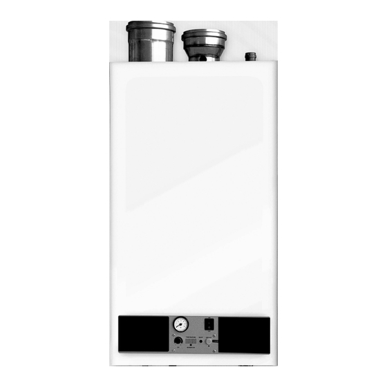
Clyde CG
Wall hung condensing boilers
Engineering Data Sheet 769/4
November 2007
Advertisement
Table of Contents

Related Manuals for Clyde CG Series


Summary of Contents for Clyde CG Series
- Page 1 Clyde CG Natural Gas 60 kW 180 kW Wall hung condensing boilers LP Gas 60 kW 120 kW Contents Page General information 2 & 3 Dimensions and Data Installation requirements 5 & 6 Boiler wiring diagram 7 & 8 Flue systems...
-
Page 2: General Information
General information Operating principles The CG is a wall-mounted condensing boiler with stainless steel counter flow twin heat exchangers (the CG 60 has a single heat exchanger), pre-mix gas burner and integral flue products fan (refer Figs 1 and 2). When operating in condensing mode with a flow of 50°C and a return of 30°C, it will give efficiencies of up to 109.5% (ncv). -
Page 3: General Information
Clyde undertake commissioning of boilers. Commissioning deposits from the system water and/or there is no charges do not include servicing during the guarantee documented evidence of commissioning by Clyde or their period, although this may be carried out under service appointed engineer. - Page 4 Dimensions and Technical data Co HI Side Plan Below Dim e nsions Bo ile r m o d e l / o u tp u t 1 0 0 1 2 0 1 5 0 1 8 0 Bo ile r flo w co n n e ctio n R 1 ½...
-
Page 5: Installation Requirements
Clyde recommend that a permanent means of room ceiling exceeds 40°C. filtration be fitted into the return pipework, such as a For a single 60 kW boiler with a Type B powered flue, the sludge trap, hydrocyclone or full flow duplex filters. -
Page 6: Installation Requirements
Installation requirements Heat exchanger hydraulic resistance The CG boiler has a high resistance heat exchanger. A Grundfos or DAB pump is supplied as an integral part of the boiler to overcome this resistance and ensure a constant water flow through the boiler. This is not a system circulating pump. -
Page 7: Boiler Wiring Diagram
Boiler wiring diagram For strip connector details, refer to Fig 4 on page 8 EDS769/4 page7 For latest prices and delivery to your door visit MyTub Ltd - 0845 303 8383 - www.mytub.co.uk - info@mytub.co.uk... -
Page 8: Boiler Wiring Diagram
Boiler wiring diagram Fit link if not using PRT 11 12 13 14 15 16 17 18 19 20 21 22 23 24 25 26 230 Vac Fig 4 Termination of external control components to the strip connector Note Remote indication LO = Lock out lamp connection D = Demand (run) lamp connection When driving external controls directly from the Furimat 914 controller without using a relay, the following maximum... - Page 9 BS 5440-2:, BS 6644:2005 or IGEM/UP/10 as appropriate - refer page Type B powered flue common headers for multiple boilers - contact Clyde for information on these. Type C concentric flues The standard horizontal and vertical flue kits are 80/125 mm for the CG 60 and 80 and 100/150 mm for the CG 100, 120, 150 and 180 models - refer Figs 5 and 6.
- Page 10 Flue systems Flue component Resistance Resistance Resistance Resistance Resistance Resistance (Pa) CG60 (Pa) CG80 (Pa) CG100 (Pa) CG120 (Pa) CG150 (Pa) CG180 80/125 concentric wall terminal 100/150 concentric wall terminal 80/125 concentric roof terminal 100/150 concentric roof terminal 80/125 concentric pipe (per m) 100/150 concentric pipe (per m) 80/125 concentric 45°...
- Page 11 Flue systems H , I Fig 7 Location of concentric balanced flue terminals Key to Fig 7 Directly below an opening 300 mm Below gutters, soil pipes or drain pipes 75 mm Below soffit / eaves 200 mm Below balconies or car port roof 200 mm From a vertical soil pipe or drain pipe 75 mm...
- Page 12 Note that the maximum electrical current that can be switched by each EBC is 2A, so additional relays (not supplied by Clyde) may be needed. The arrangement shown in Fig 8 will heat a single heating circuit, directly compensated on the common boiler flow temperature.
- Page 13 Hydraulic system design and control PRT or RC Master PH KR Fig 8 Single boiler with one heating zone and optional DHW calorifier connected to the “High” temperature side of the LVH The DHW calorifier is directly controlled from the boiler via the 3-port diverting valve (DV) and DHW sensor (FB). The PRT or RC (Programmable Room Thermostat/ modulating control) gives time control of the heating circuit (the RC also gives time control of the DHW).
- Page 14 Hydraulic system design and control Master Slave 1 Fig 10 Up to 8 boilers in cascade with optional DHW on “Low”temperature side of LVH. The DHW calorifier is directly controlled by the master boiler via the sensor (FB) and loading pump (PS). The boilers are connected together by a cascade bus.
- Page 15 All offers and sales are subject to the Company's current terms and conditions of sale, a copy of which is available on request. Unit 10 Lion Park Avenue Chessington Surrey KT9 1ST Clyde Energy Solutions Ltd 020 8391 2020 020 8397 4598 EDS 769/4 info@clyde-nrg.com...
Need help?
Do you have a question about the CG Series and is the answer not in the manual?
Questions and answers