Table of Contents
Advertisement
Quick Links
Advertisement
Chapters
Table of Contents

Related Manuals for Omron ZUV Series

Summary of Contents for Omron ZUV Series
- Page 1 Smart Curing System Mega Power Type ZUV Series User's Manual Cat. No. Z281-E1-02...
- Page 2 Introduction Thank you for purchasing the ZUV. This manual provides information regarding functions, performance and operating methods that are required for using the ZUV. When using the ZUV, be sure to observe the following: • The ZUV must be operated by personnel knowledgeable in electrical engineering. •...
- Page 3 Terms and Conditions Agreement Introduction OVERVIEW & INSTALLATION AND CONNECTION Section 1 ZUV BASIC OPERATION Section 2 SETUP Section 3 CONNECTING TO EXTERNAL DEVICES Section 4 APPENDIX Section 5 User's Manual Smart Curing System Mega Power Type ZUV Series...
- Page 4 Omron’s exclusive warranty is that the Products will be free from defects in materials and workmanship for a period of twelve months from the date of sale by Omron (or such other period expressed in writing by Omron). Omron disclaims all other warranties, express or implied.
- Page 5 It may represent the result of Omron’s test conditions, and the user must correlate it to actual application requirements. Actual performance is subject to the Omron’s Warranty and Limitations of Liability.
- Page 6 Product. ■ Errors and Omissions Information presented by Omron Companies has been checked and is believed to be accurate; however, no responsibility is assumed for clerical, typographical or proofreading errors or omissions.
-
Page 7: Meanings Of Alert Symbols
Introduction Meanings of Signal Words Meanings of Signal Words The following signal words are used in this manual. Indicates a potentially hazardous situation which, if not avoided, will result in minor or moderate injury, or may result in serious injury or death. Additionally there may be significant property damage. -
Page 8: Alert Statements In This Manual
Introduction Alert statements in this Manual Alert statements in this Manual The following alert statements apply to the products in this manual. Each alert statement also appears at the locations needed in this manual to attract your attention. Never look directly at or allow your skin to be exposed to the ultraviolet light. -
Page 9: Precautions For Safe Use
• Should you notice any abnormalities such as smoke, abnormal heat of the product surface, and/or any foul odor, immediately stop use, turn OFF the power supply, and disconnect the power plug from the outlet. Contact your OMRON representative for repair of the product. Repairing it by yourself may cause danger. - Page 10 Introduction Precautions for Safe Use • Do not insert any foreign objects into the product through the ventilation hole or any other opening. Doing so may cause a fire or electric shock. • Do not install multiple controllers close to others, or do not pile them up. Doing so may cause a fire or breakdown of the product.
-
Page 11: Precautions For Correct Use
Introduction Precautions for Correct Use Precautions for Correct Use Please observe the following precautions to prevent faulty operation and malfunction of the product and adverse influence on performance and devices. 1.Installation Site Do not install the product in locations subjected to the following: •... - Page 12 Introduction Precautions for Correct Use 3.Cleaning • Do not use paint thinner, benzene, acetone, or kerosene for cleaning since these solutions dissolve the product surface. • Use commercially available alcohol. • To remove dirt or dust particles from the lens, wipe gently with a soft cloth (for cleaning lenses) moistened with a small amount of alcohol.
-
Page 13: Editor's Note
Introduction Editor's Note Page Format Title of each section Header Overview Section 3 Section 3 Setting of the Irradiation Conditions Setting of the Irradiation Conditions Setting the Constant Irradiation Conditions Setting the Constant Irradiation Conditions Irradiation power and time are set for the purpose of continually irradiating the UV light for a certain time with a constant irradiation intensity. - Page 14 Introduction ■ Meaning of Symbols Menu items that are displayed on the controller's LCD screen, and window, dialog boxes and other GUI elements displayed on the PC are indicated enclosed by brackets [ ]. ■ Visual Aids Indicates points that are important to ensure full product performance, such as operational precautions and application procedures.
-
Page 15: Table Of Contents
Introduction CONTENTS CONTENTS Meanings of Signal Words Meanings of Alert Symbols Alert statements in this Manual Precautions for Safe Use Precautions for Correct Use Editor's Note Page Format CONTENTS Section 1 OVERVIEW & INSTALLATION AND CONNECTION Basic Configuration Part Names and Functions Controller Head Installation &... -
Page 16: Contents
Introduction CONTENTS Section 3 SETUP LOCK Mode Setting Item List Setting the Irradiation Conditions Setting Constant Irradiation Conditions Setting Pattern Irradiation Copying Irradiation Conditions Device Setup Change Setting (Bank) 3-11 Switching Banks 3-12 Copying Banks 3-12 Clearing Banks 3-12 Enabling Bank Switching Input 3-13 Setting/Executing Power Tuning 3-14... - Page 17 Introduction CONTENTS Section 5 APPENDIX Troubleshooting Error Messages and Countermeasures Q&A Maintenance of the Head Cleaning the Lens Unit Replacing the Lens Unit Specifications and External Dimensions Controller Requirements from Regulations and Standards Summary of Requirements to Manufactures Summary of Requirements to User 5-10 Definitions of Laser Classification 5-11...
-
Page 18: User's Manual
Introduction CONTENTS MEMO User's manual... -
Page 19: Section 1 Overview & Installation And Connection
S e c t i o n 1 OVERVIEW & INSTALLATION AND CONNECTION Basic Configuration Part Names and Functions Controller Head Installation & Connection Before Installation and Connection Installing the Controller Installing the Head Connecting Devices User’s Manual... -
Page 20: Basic Configuration
• AC power supply: AC adapter is used (supplied with the product) • DC power supply: supplied from the terminal block on the rear Recommended power supply unit: S8VS-18024 (24 VDC 7.5A) by OMRON USB cable Personal computer User’s Manual... -
Page 21: Part Names And Functions
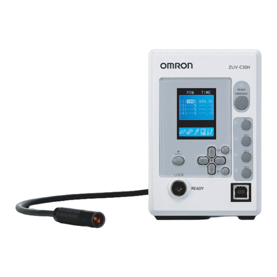
Section 1 Part Names and Functions Part Names and Functions This section describes the names and functions of parts on the controller and head. Controller ■ Front (1) UV ON indicator (2) EMISSION button (11) LCD screen (3) CH1 to CH4 buttons (10) ESC key (9) MENU key (8) Control keys... -
Page 22: Head
Section 1 Part Names and Functions ■ Rear (1) RS-232C connector (5) Head connector (2) I/O terminal block (3) Power supply switch (4) AC adapter jack Name Function RS-232C connector Connects to the personal computer or programmable controller via the serial cable to control input from external devices. -
Page 23: Installation & Connection
Section 1 Installation & Connection Installation & Connection Before Installation and Connection ■ Checking the installation environment Read "Precautions for Safe Use" at the beginning of this manual, and check the installation environment. ■ Checking the installation site Read "Precautions for Correct Use" at the beginning of this manual, and check the installation site. -
Page 24: Installing The Head
Section 1 Installation & Connection Installing the Head Never look directly at or allow your skin to be exposed to the ultraviolet light. To prevent exposure to ultraviolet light, never look into the ultraviolet light. Workers should wear protective goggles and equipment to protect from being exposed to reflected light. - Page 25 Section 1 Installation & Connection ■ Connecting the Head Install the head using the mounting bracket supplied with the head. Insert the head into the mounting bracket. (Unit: mm) Mounting bracket Fix the head to the mounting bracket. Screws: M3 x 2 Tightening torque: 0.9 N•m or more to 1.5 N•m or less Be sure to use the screws supplied with the head.
-
Page 26: Connecting Devices
Section 1 Installation & Connection Connecting Devices • Before connecting/disconnecting peripheral devices, make sure that the controller is turned OFF. • For details on connecting external devices, see "Section 4 CONNECTING TO EXTERNAL DEVICES." Never look directly at or allow your skin to be exposed to the ultraviolet light. -
Page 27: Section 2 Zuv Basic Operation
S e c t i o n 2 ZUV BASIC OPERATION Starting Up and Shutting Down Let's Try Irradiation Irradiating at Constant Power Creating Irradiation Patterns for Irradiation Operating Modes 2-11 Function Setting Mode - LOCK mode 2-13 Operation-in-progress Mode - READY Mode 2-15 User’s Manual... -
Page 28: Starting Up And Shutting Down
Section 2 Starting Up and Shutting Down Starting Up and Shutting Down Never look directly at or allow your skin to be exposed to the ultraviolet light. To prevent exposure to ultraviolet light, never look into the ultraviolet light. Workers should wear protective goggles and equipment to protect them from being exposed to reflected light. - Page 29 Section 2 Starting Up and Shutting Down ■ Shutting Down Save the setting data before turning OFF the power supply. All settings will be deleted if you turn the power OFF without saving the data. Saving the setting data Press the key to save setting data.
-
Page 30: Let's Try Irradiation
Section 2 Let's Try Irradiation Let's Try Irradiation This section describes the basic operating procedures from setting the irradiation conditions up to performing constant irradiation or pattern irradiation. Confirmation of Installation and Connection p.1-5 Installation & Connection Starting Up p.2-2 Starting Up and Shutting Down Irradiating at Constant Power Creating Irradiation Patterns for Irradiation... -
Page 31: Irradiating At Constant Power
Section 2 Let's Try Irradiation Irradiating at Constant Power In this irradiation mode, irradiation is performed continuously at constant irradiation power for a specified time. Irradiation power Irradiation time (s) This section describes the procedures from setting the irradiation power to "65%" and the irradiation time to "60 seconds"... - Page 32 Section 2 Let's Try Irradiation Change the numerical value using the keys and the digit using the keys, and press the SET key to apply the setting. Set the irradiation power to "65%" and the irradiation time to "60 seconds". •...
-
Page 33: Creating Irradiation Patterns For Irradiation
Section 2 Let's Try Irradiation Creating Irradiation Patterns for Irradiation Irradiation patterns can be created in combination with irradiation power and irradiation time for the purpose of irradiation. <Step type> <Linear type> Irradiation power Irradiation power (max. 16) (max. 16 steps) STEP2 STEP4 STEP5 STEP3... - Page 34 Section 2 Let's Try Irradiation Creating irradiation patterns Move the cursor to [01] using the keys, PATTERNSELECT and press the SET key. Change the numeric values and number of digits by using the ↑ ↓ UP/DOWN keys and the ← → L/R keys, respectively.
- Page 35 Section 2 Let's Try Irradiation Selecting irradiation patterns Press the ESC key once. CH SET The screen display returns to the one 1.1CH 2.2CH shown on the right. 3.3CH 4.4CH 5.CH COPY 6.PATTERN EDIT Move the cursor to [1CH] using the keys, and press the SET key.
- Page 36 Section 2 Let's Try Irradiation Irradiating UV light Press the key to save the settings, and turn the key switch to the [READY] position to switch to the READY mode. SAVE SETTING DATA The save confirmation message is displayed when EXE CAN the mode is switched to the READY mode without saving the setting data using the MENU key.
-
Page 37: Operating Modes
Section 2 Operating Modes Operating Modes The ZUV has the following two operating modes. Switch to the desired mode before you start operation. To switch to the operating mode, use the key switch. In the LOCK mode In the READY mode ALL CH STATE POWER/TIME :CHANGE DISP... - Page 38 Section 2 Operating Modes Change the numerical value using the keys and the digit using the keys, enter all four digits, and press the SET key to apply the setting. Move the cursor to [OK] using the key, and press the SET key. The password lock is canceled, and the display returns to the LOCK mode top screen.
-
Page 39: Function Setting Mode - Lock Mode
Section 2 Operating Modes Function Setting Mode - LOCK mode The LCD screen displays the setting menus. CH SET TOOL Irradiation Conditions Tool Setting Menu Setting Menu SYSTEM External Device System Environment Setting Menu Setting Menu BANK Device Setup Change Setting (BANK) Menu ●... - Page 40 Section 2 Operating Modes ● System Environment Setting Menu This menu sets the system environment. SYSTEM ■ Disabling the Irradiation Buttons p.3-22 ■ Changing the Display Language p.3-21 ■ Setting the I/O Signal Conditions p.3-21 ■ Initializing Settings Data p.3-22 ■...
-
Page 41: Operation-In-Progress Mode - Ready Mode
Section 2 Operating Modes Operation-in-progress Mode - READY Mode The LCD screen displays the irradiation information. The screen display order can be changed to counterclockwise or to clockwise by the L key and R key, respectively. Irradiation Conditions Irradiation Power List Display Adjustment ALL CH STATE... - Page 42 Section 2 Operating Modes ● Irradiation Power Adjustment This menu changes the irradiation power. • The irradiation power can be adjusted only in constant irradiation. ADJUSTMENT The currently set irradiation power is displayed. The currently set channel is displayed. :CHANGE CH :CHANGE DISP The irradiation power can be changed using the UP/DOWN keys.
- Page 43 Section 2 Operating Modes ● Channel Specific Detail Display This displays the irradiation pattern and progress in graph form. Displays the channel shown as a graph. 1CH UV LVL The head state is displayed. READY: Irradiation is enabled. BUSY: Irradiation is disabled. LIGHT: Irradiation in progress OFF:...
- Page 44 Section 2 Operating Modes MEMO 2-18 User’s Manual...
-
Page 45: Section 3 Setup
S e c t i o n 3 SETUP LOCK Mode Setting Item List Setting the Irradiation Conditions Setting Constant Irradiation Conditions Setting Pattern Irradiation Copying Irradiation Conditions Device Setup Change Setting (Bank) 3-11 Switching Banks 3-12 Copying Banks 3-12 Clearing Banks 3-12 Enabling Bank Switching Input... -
Page 46: Lock Mode Setting Item List
Section 3 LOCK Mode Setting Item List LOCK Mode Setting Item List The setting items of the LOCK mode are shown as follows: Default Settings Option/Range Pages LOCK mode Value CH SET 1CH to 4CH p.3-4 LIGNT SETTING p.3-5 TIME UNLIMITED Pattern irradiation 01 to 16... - Page 47 Section 3 LOCK Mode Setting Item List Default Settings Option/Range Pages Value SYSTEM COMM PORT DATA BIT 8BIT 8BIT, 7BIT p.4-9 PARITY NON, ODD, EVEN STOP BIT 1BIT 1BIT, 2BIT BAUD RATE 38400 9600A19200A38400A57600 A115200 DELIMITER CR+LF CR, LF, CR+LF PASSWORD ON/OFF p.3-20 CHANGE...
-
Page 48: Setting The Irradiation Conditions
Section 3 Setting the Irradiation Conditions Setting the Irradiation Conditions Simultaneous adhesion is available for multiple locations under differing conditions by setting the irradiation conditions. Two ways of irradiation are provided: constant irradiation, which irradiates at constant power for a certain time, and pattern irradiation, which irradiates by gradating the power with a pattern setting of power and time. -
Page 49: Setting Constant Irradiation Conditions
Section 3 Setting the Irradiation Conditions Setting Constant Irradiation Conditions Irradiation power and time are set for the purpose of continually irradiating the UV light for a certain time at a constant irradiation intensity. Continuous Irradiation power irradiation of UV light for a certain time at constant irradiation power... -
Page 50: Setting Pattern Irradiation
Section 3 Setting the Irradiation Conditions Setting Pattern Irradiation Irradiation patterns can be freely set as a combination of irradiation power and time. Optimal irradiation can be performed by creating and selecting patterns suited to the type of object and adhesion. To use a pattern To select To change... - Page 51 Section 3 Setting the Irradiation Conditions ■ Pattern name setting Names can be freely set for set patterns. Pattern name setting LOCK mode-[CH SET]-[PATTERN EDIT] Move the cursor to the target pattern using the PATTERNSELECT keys, and press the key. : NAMING Select characters using the keys, and...
- Page 52 Section 3 Setting the Irradiation Conditions ■ Selecting patterns Select which pattern is to be used for the respective channel. Patterns must already have been prepared in advance. Creating patterns p.3-6 LOCK mode-[CH SET]-[1CH to 4CH]-[PATTERN] Setting value Description 01 to 16 Select the irradiation pattern.
-
Page 53: Copying Irradiation Conditions
Section 3 Setting the Irradiation Conditions Copying Irradiation Conditions Copy the irradiation conditions to another channel. ■ Batch copy LOCK mode-[CH SET]-[CH COPY]-[BATCH COPY] Move the cursor to the copy source using the BATCH COPY keys, and press the SET key. FROM :[01]CH Set a channel using the keys, and... - Page 54 Section 3 Setting the Irradiation Conditions Set a channel using the keys, and press the SET key. Change the numeric values and number of digits by using the ↑ ↓ UP/DOWN keys and the ← → L/R keys, respectively. Move the cursor to [EXE] using the keys, CH COPY and press the SET key.
-
Page 55: Device Setup Change Setting (Bank)
Section 3 Device Setup Change Setting (Bank) Device Setup Change Setting (Bank) Up to 16 types of irradiation methods can be stored in the ZUV, and a set of these methods is called a "bank". Banks can be changed from an external device when changing device setups. -
Page 56: Switching Banks
Section 3 Device Setup Change Setting (Bank) Switching Banks Switch the currently selected bank to another bank. Banks can also be switched from an external device. • I/O terminal block p.4-3 • USB/RS-232C communication command p.4-14 LOCK mode-[BANK]-[CHANGE] Setting value Description CHANGE Selects the target bank. -
Page 57: Enabling Bank Switching Input
Section 3 Device Setup Change Setting (Bank) Enabling Bank Switching Input Enable/disable bank switching input from the I/O terminal on the controller rear. LOCK mode-[BANK]-[TERMINAL] Setting value Description Disables bank switching input. (default value) Be sure to set bank switching input to OFF unless the bank is changed using the I/O terminal. -
Page 58: Setting/Executing Power Tuning
Section 3 Setting/Executing Power Tuning Setting/Executing Power Tuning The "power tuning" function corrects the irradiation power according to the measurement result obtained by connecting a UV luxmeter to ZUV. The reference irradiation power and the measured intensity are registered in advance so that easy correction of the irradiation power can be made later at checkup. - Page 59 Section 3 Setting/Executing Power Tuning Setting [POWER TUNING] to [ON] lowers the actual irradiation intensity when compared with the state of the [OFF] setting even if the same irradiation power is set. Output (irradiation) light intensity Execute Execute Execute Time ●...
- Page 60 Section 3 Setting/Executing Power Tuning ■ Setting the reference value The reference UV irradiation power and the measured intensity are registered as reference values. LOCK mode-[TOOL]-[POWER TUNING]-[ON]-[TEACH] Turn the key switch to READY. Move the cursor to [CHANNEL] using the TEACH CHANNEL:[01]CH keys, and press the SET key.
- Page 61 Section 3 Setting/Executing Power Tuning ■ Correcting to a reference value Tune the controller to the currently set reference value. LOCK mode-[TOOL]-[POWER TUNING]-[ON]-[EXECUTE] Turn the key switch to READY. Move the cursor to [CHANNEL] using the EXECUTE CHANNEL:[01]CH keys, and press the SET key. Set a target channel using the keys, and press the SET key.
-
Page 62: Displaying Irradiation Log Data
Section 3 Displaying Irradiation Log Data Displaying Irradiation Log Data When the irradiation log data management screen is enabled, up to 100 log data records are saved on the controller. The following section describes how to display the irradiation log data. LOCK mode-[TOOL]-[LOG DATA] LOG DATA NO.CH TIME... -
Page 63: Setting Cumulative Alarms
Section 3 Setting Cumulative Alarms Setting Cumulative Alarms The cumulative energy of each head is stored on controllers. The head life can be judged by setting thresholds to this energy value. An alarm is displayed and an error is output when the cumulative energy of the head exceeds the threshold. -
Page 64: Setting The System Environment
Section 3 Setting the System Environment Setting the System Environment Setting Passwords Set enable/disable of the password function, and set/change of the password. LOCK mode-[SYSTEM]-[PASSWORD] Setting value Description Disables the password function. (default value) The previously set password is canceled. Enables the password function. -
Page 65: Setting The Buzzer Function
Section 3 Setting the System Environment Setting the Buzzer Function Set the buzzer sound to notify start and end of adhesion irradiation. LOCK mode-[SYSTEM]-[BUZZER] Setting value Description Sets the buzzer volume to OFF. Sets the buzzer volume to ON (default value). Changing the Display Language Set the display language of the LCD screen. -
Page 66: Initializing Setting Data
Section 3 Setting the System Environment Initializing Setting Data Return all bank settings and system settings to their factory settings. All bank and system settings are initialized regardless of the currently selected bank No. LOCK mode-[SYSTEM]-[ALL CLEAR] Setting value Description SYSTEM DATA Initializes the bank and system setting data. -
Page 67: Setting The Display Method
Section 3 Setting the System Environment Setting the Display Method ■ Setting/Canceling the ECO Mode Set the brightness of the LCD screen. LOCK mode-[SYSTEM]-[DISPLAY]-[ECO] Setting value Description Sets the "Eco" mode. The "Eco" screen darkens when three minutes continue without any operation. - Page 68 Section 3 Setting the System Environment MEMO 3-24 User’s Manual...
-
Page 69: Section 4 Connecting To External Devices
S e c t i o n 4 CONNECTING TO EXTERNAL DEVICES Connection by an I/O Terminal Block Connection and Communication Settings Timing Charts Connection by USB/RS-232C Connection and Communication Settings USB Driver 4-11 Communication Commands 4-14 Setting Hyper Terminal 4-37 User’s Manual... -
Page 70: Connection By An I/O Terminal Block
Section 4 Connection by an I/O Terminal Block Connection by an I/O Terminal Block Connection and Communication Settings This section describes how to connect the controller to the external device using the I/O terminal block. Before connecting/disconnecting the external device, make sure that the controller is turned OFF. ■... - Page 71 Section 4 Connection by an I/O Terminal Block ● I/O terminal pin assignments Pay attention to the following points regarding the electric wire used for the terminal block: • The size of the recommended cross section is as follows: Numbers 16, 31, and 32: 1.00 to 1.50 mm Other than the above: 0.10 to 1.50 mm •...
- Page 72 Section 4 Connection by an I/O Terminal Block ● Internal specifications <Input specifications> Internal circuit diagram 8.5 V Respective input terminal COM IN <Output specifications> Output voltage 12 to 24 VDC ±10% Load current 45 mA or smaller ON residual voltage 2 V or smaller OFF leakage current 0.1 mA or smaller...
- Page 73 Section 4 Connection by an I/O Terminal Block Terminal Signal Name Functions Block Emergency stop input Stops UV light irradiation in an emergency. Set the conditions for enabling emergency stop input at [I/O]- [EMERGENCY]. To return from the emergency stop state, set the terminal to disable.
-
Page 74: Timing Charts
Section 4 Connection by an I/O Terminal Block Timing Charts The following shows the timing charts when communication is performed with external devices. ■ Ready output/display Ready output turns ON when the controller is ready for irradiation. <Batch Control> CH1 irradiation CH1 READY CH2 irradiation CH2 READY... - Page 75 Section 4 Connection by an I/O Terminal Block ■ Channel 1 irradiation terminal input (batch control) This input starts/stops UV irradiation of all channels. 40 ms/120 ms 40 ms/120 ms 40 ms/120 ms TRG1 ON CH1 irradiation CH1 READY CH2 irradiation CH2 READY 200 ms •...
- Page 76 Section 4 Connection by an I/O Terminal Block ■ Trigger signal input priority conditions Select which of preset time or interrupt input signal to give priority to for trigger signal input. <When priority is set to time> Set irradiation end time 40 ms/120 ms 40 ms/120 ms 40 ms/120 ms...
-
Page 77: Connection By Usb/Rs-232C
Section 4 Connection by USB/RS-232C Connection by USB/RS-232C Connection and Communication Settings This section describes how to connect the controller to an external device using the USB/ RS-232C cable. Before connecting/disconnecting the external device, make sure that the controller is turned OFF. ■... - Page 78 Section 4 Connection by USB/RS-232C ■ RS-232C connection Plug one end of the RS-232C cable into Controller rear the RS-232C connector of the controller. Plug the other end of the RS-232C cable Personal computer into the RS-232C connector of the external device.
-
Page 79: Usb Driver
Section 4 Connection by USB/RS-232C USB Driver To establish a connection between the personal computer and the controller by the USB interface, the USB driver must be installed on a personal computer. • The exclusive USB driver must be installed only when the controller is connected to the personal computer for the first time. - Page 80 Section 4 Connection by USB/RS-232C Click the [Next>] button. Select the [Search for a suitable driver for my device (recommended)] radio button, and click the [Next>] button. Select the [CD-ROM drives] checkbox, and click the [Next>] button. In the event that the controller is not automatically detected: Click the [Browse] button and select the [USB] folder on the CD-ROM.
- Page 81 Section 4 Connection by USB/RS-232C Make sure that the suitable driver has been detected, and click the [Next>] button. Installation begins. When installation completes, the completion message is displayed. Click the [Finish] button. The same screen in step 2 is displayed. Repeat the above procedure. This completes installation of the USB driver.
-
Page 82: Communication Commands
Section 4 Connection by USB/RS-232C Communication Commands To communicate with an external device, switch the controller to the READY mode. In the LOCK mode, a communication cannot be established with the external device. ■ Non-procedural command list Reference Command Name Details Pages START... - Page 83 Section 4 Connection by USB/RS-232C ■ Command basic format ● Command format The non-procedural command format is as follows: Example: UV irradiation start command START command Delimiter Space (20h) • Enter a space (20h) between a command and an argument, or between arguments. •...
- Page 84 Section 4 Connection by USB/RS-232C ■ Details of respective command START/STOP commands UV light irradiation is started by the START command and is stopped by the STOP command on the specified channel. Setting the <channel No.> to 0 starts/stops irradiation for all heads at once starting with the irradiation standby head. •...
- Page 85 Section 4 Connection by USB/RS-232C BANKGET command This command obtains the currently set bank No. BANKGET Command Delimiter Delimiter <Bank No.> Delimiter Delimiter Response Delimiter Delimiter Parameter description The following parameter can be obtained by the BANKGET command: Parameter Setting Range/Output Range Bank No.
- Page 86 Section 4 Connection by USB/RS-232C BANKSET command This command switches banks. BANKSET <Switch destination bank No.> Command Delimiter Delimiter Response Delimiter Delimiter Parameter description The following parameter can be set by the BANKSET command: Parameter Setting Range/Output Range Switch destination bank No. 1 to 16: BANK1 to BANK16 Command/response examples The following shows an example of this command:...
- Page 87 Section 4 Connection by USB/RS-232C DATASAVE command This command saves the setting data to the flash memory in the controller. All settings will be deleted if you turn the power OFF without saving the data. Setting data can also be saved by menu operations without using commands. Turn the key switch on the controller front, and change the LOCK mode to the READY mode.
- Page 88 Section 4 Connection by USB/RS-232C BANKLOAD/BANKSAVE commands Specified bank data is loaded by the BANKLOAD command and saved by the BANKSAVE command. Confirm the [READY] response after the command is sent to perform file send/receive operations using the tools provided by the personal computer, (for example, from Hyper Terminal) by XMODEM.
- Page 89 Section 4 Connection by USB/RS-232C SYSLOAD/SYSSAVE commands System data is loaded by the SYSLOAD command and saved by the SYSSAVE command. Confirm the [READY] response after the command is sent to perform file send/receive operations using the tools provided by the personal computer, (for example, from Hyper Terminal) by XMODEM.
- Page 90 Section 4 Connection by USB/RS-232C PATNGET command This command obtains display type-specific and step-specific irradiation power and time for from the irradiation pattern settings. PATNGET <Pattern No.> Command Delimiter Delimiter <Type><STEP1 level><STEP1 time><STEP2 level><STEP2 Response time> ... <STEP16 level><STEP16 time> Delimiter Delimiter Delimiter...
- Page 91 Section 4 Connection by USB/RS-232C PATNSET command This command sets the display type-specific and step-specific irradiation power and time for the respective irradiation pattern. PATNSET <Pattern No.> <Type> <STEP1 level> <STEP1 time> Command <STEP2 level> <STEP2 time> ... <STEP16 level> <STEP16 time>...
- Page 92 Section 4 Connection by USB/RS-232C PNAMEGET command This command obtains irradiation pattern names. Only set irradiation pattern names are returned. PNAMEGET <Pattern No.> Command Delimiter Delimiter <Pattern name> Delimiter Delimiter Response Delimiter Delimiter Parameter description The following parameters can be set and obtained by the PNAMEGET command: Parameter Setting Range/Output Range Pattern No.
- Page 93 Section 4 Connection by USB/RS-232C PNAMESET command This command sets irradiation pattern names. PNAMESET <Pattern No.> <Pattern name> Command Delimiter Delimiter Response Delimiter Delimiter Parameter description The following parameters can be set by the PNAMESET command: Parameter Setting Range/Output Range Pattern No.
- Page 94 Section 4 Connection by USB/RS-232C DATAGET command This command obtains the irradiation conditions of the respective channel. DATAGET <Channel No.> <Parameter No.> Command Delimiter Delimiter <Obtained data> Delimiter Delimiter Response Delimiter Delimiter Parameter description The following parameters can be set and obtained by the DATAGET command: Parameter Setting Range/Output Range Channel No.
- Page 95 Section 4 Connection by USB/RS-232C DATASET command This command sets the irradiation conditions of the respective channel. DATASET <Channel No.> <Parameter No.> <Write Command data> Delimiter Delimiter Response Delimiter Delimiter Parameter description The following parameters can be set by the DATASET command: Parameter Setting Range/Output Range Channel No.
- Page 96 Section 4 Connection by USB/RS-232C LOGDATA command This command obtains the irradiation log data for the specified number of obtained data retroactive from the latest irradiation data (irradiation completed data). LOGDATA <Number of obtained data> Command Delimiter Delimiter <Target channel><Irradiation start time><Irradiation end Response time>...
- Page 97 Section 4 Connection by USB/RS-232C ACCUMGET command This command obtains cumulative energy values currently stored on the controller in individual channels. This command is enabled only when a head is connected to the target channel. An error response is returned when a head is not connected. ACCUMGET <Target channel>...
- Page 98 Section 4 Connection by USB/RS-232C SYSGET command This command obtains system data. SYSGET <Parameter No.> Command Delimiter Delimiter <Obtained data> Delimiter Delimiter Response Delimiter Delimiter Parameter description The following parameters can be set and obtained by the SYSGET command: Parameter Details Obtained data (Setting range/Output range) READY mode display data No.
- Page 99 Section 4 Connection by USB/RS-232C Parameter Details Obtained data (Setting range/Output range) RS-232C/USB delimiter 0: CR 1: LF 2: CR+LF EMISSION button lock 0: OFF 1: ON Channel irradiation button lock 0: OFF 1: ON Command/response examples The following shows an example of this command: ←...
- Page 100 Section 4 Connection by USB/RS-232C SYSSET command The system data is set. SYSSET <Parameter No.> <Write data> Delimiter Delimiter Command Delimiter Delimiter Response Parameter description The following parameters can be obtained by the SYSSET command: Parameter Details Write Data (Setting Range/Output Range) READY mode display data No.
- Page 101 Section 4 Connection by USB/RS-232C Parameter Details Write Data (Setting Range/Output Range) RS-232C/USB delimiter 0: CR 1: LF 2: CR+LF EMISSION button lock 0: OFF 1: ON Channel irradiation button lock 0: OFF 1: ON Command/response examples The following shows an example of this command: ←...
- Page 102 Section 4 Connection by USB/RS-232C CALIBGET/CALIBSET commands The reference value for power tuning is set by the CALIBGET command and executed by the CALIBSET command. • CALIBGET <Channel No.> Delimiter Delimiter Command • CALIBSET <Channel No.> Delimiter Delimiter Response Delimiter Delimiter Parameter description The following parameter can be set by the CALIBGET and CALIBSET commands:...
- Page 103 Section 4 Connection by USB/RS-232C VERGET command This command obtains system version information. VERGET Command Delimiter Delimiter <Software version> Delimiter Delimiter Response Delimiter Delimiter Parameter description The following parameter can be obtained by the VERGET command: Parameter Setting Range/Output Range Software version ZUV-C30H VER.X.XXX(X=0-9) Command/response examples...
- Page 104 Section 4 Connection by USB/RS-232C HDATACLR command This command initializes the cumulative irradiation energy and power tuning data saved on the controller. After the head is replaced, be sure to initialize this data. HDATACLR <Channel No.> Command Delimiter Delimiter Response Delimiter Delimiter Parameter description...
-
Page 105: Setting Hyper Terminal
Section 4 Connection by USB/RS-232C Setting Hyper Terminal The example in this section describes the procedure for performing communications by non-procedural commands on the Windows standard tool Hyper Terminal. Start up Hyper Terminal. Hyper Terminal is provided under the [Communication] folder, which you can access by starting with the [Program] pop-up menu and selecting the [Accessory] folder. - Page 106 Section 4 Connection by USB/RS-232C (3) Set the communication conditions. In the case of the USB connection, set [Bits per second] to [115200]. (4) Hyper Terminal is started up. 4-38 User’s Manual...
- Page 107 Section 4 Connection by USB/RS-232C Set items such as echoback for easier understanding of command transactions. (1) Select [Properties] to open the [ZUV Properties] dialog box. (2) Select the [Settings] tab and select [ASCII Setup...]. (3) Select the following checkboxes. After selecting the desired checkboxes, click [OK].
- Page 108 Section 4 Connection by USB/RS-232C Set the ZUV communication conditions. (1) Match the LOCK mode-[SYSTEM]-[COM] settings to the settings on the personal computer. (2) Switch the controller to the READY mode. Execute non-procedural communications. (1) Enter a command. Press the RETURN key after entering the command. (2) Obtain a response from the controller according to the command.
- Page 109 S e c t i o n 5 APPENDIX Troubleshooting Error Messages and Countermeasures Q&A Maintenance of the Head Cleaning the Lens Unit Replacing the Lens Unit Specifications and External Dimensions Controller Requirements from Regulations and Standards Summary of Requirements to Manufactures Summary of Requirements to User 5-10 Definitions of Laser Classification...
-
Page 110: Troubleshooting
Section 5 Troubleshooting Troubleshooting This section describes countermeasures for temporary hardware problems. Before sending the hardware for repair, check the problem in this section. Problem Probable cause and possible countermeasure Pages The device restarts during • Is the power supply device connected correctly? p.1-8 operation. -
Page 111: Error Messages And Countermeasures
Clear flash memory in the controller by (ROM) memory. holding down the SET key for 3 seconds. Contact your OMRON representative if normal operation is not restored. SYSTEM ERROR The head has become loose or Check to see if the head is connected, and... -
Page 112: Q&A
Q&A, Maintenance of Head Q&A Question Answer I've lost the hardware key. What should I do? Contact your OMRON sales representative. Which settings are initialized when settings are All settings except the cumulative irradiation energy and initialized? language settings are initialized. -
Page 113: Replacing The Lens Unit
Maintenance of the Head Replacing the Lens Unit Lens units with different irradiation beam diameters are provided for the ZUV series. Replace the lens unit according to the desired irradiation area or necessary intensity. Always turn OFF the power before replacing the lens. The controller may malfunction or cause an accident if the lens is replaced while the power is ON. -
Page 114: Specifications And External Dimensions
Section 5 Specifications and External Dimensions Specifications and External Dimensions Controller ZUV-C30H (Unit: mm) 63.5 23.4 21.5 30.8 13.1 4-14 dia. 12.7 12.7 12.7 12.7 User’s Manual... - Page 115 Section 5 Specifications and External Dimensions Model ZUV-C30H Applicable head ZUV-H series Irradiation Constant irradiation Irradiation power (0 to 100%), irradiation time (max.999.9 seconds/ method unlimited) Pattern irradiation Can be set to step or ramp (linear) (16 points specified per setting) Number of settings 16 banks Terminal...
-
Page 116: Requirements From Regulations And Standards
Section 5 Requirements from Regulations and Standards Requirements from Regulations and Standards Summary of Requirements to Manufactures ■ For Europe EN 60825-1 "Safety of Laser Products, Equipment Classification, Requirements and User's Guide" Summary of Manufacturer’s Requirements Classification Requirements subclause Class 1 Class 1M Class 2 Class 2M... - Page 117 Section 5 Requirements from Regulations and Standards Classification Requirements subclause Class 1 Class 1M Class 2 Class 2M Class 3R Class 3B Class 4 Wavelength range Required for certain wavelength ranges label LED label Make required word substitutions for LED products User information Operation manuals must contain instructions for safe use.
-
Page 118: Summary Of Requirements To User
Section 5 Requirements from Regulations and Standards Summary of Requirements to User ■ For Europe EN 60825-1 Requirements Classification subclause Class 1 Class 1M Class 2 Class 2M Class 3R Class 3B Class 4 required for visible Laser safety offi- Not required but recommended for applications that emission Required... -
Page 119: Definitions Of Laser Classification
Section 5 Requirements from Regulations and Standards Definitions of Laser Classification ■ For Europe Laser Product Classifications Class Description Class 1 Lasers which are safe under reasonably foreseeable conditions of operation. Class 2 Lasers emitting visible radiation in the wavelength range from 400 nm to 700 nm. Eye pro- tection is normally afforded by aversion responses including the blink reflex. - Page 120 Section 5 Requirements from Regulations and Standards 5-12 User’s Manual...
-
Page 121: Index
Section 5 INDEX INDEX Startup CORRECT AC adapter Cumulative Alarm 3-19 AC adapter jack Cumulative Energy List Display 2-17 ACCUMGET command 4-29 ALL CLEAR 3-22 DATAGET command 4-26 DATASAVE command 4-19 Bank DATASET command 4-27 Clearing 3-12 Copying 3-12 Switching 3-12 3-23 Switching Input... - Page 122 Section 5 INDEX LCD screen START/STOP commands 4-16 LINEAR STEP LOCK mode 2-13 SYSGET command 4-30 LOGDATA Command 4-28 SYSSET command 4-32 SYSTEM 3-20 Menu Device Setup Change Setting TEACH 3-16 2-13 TERMINAL 3-13 Environment Setting 2-14 Timing charts External Device Setting 2-13 Tool Setting 2-13 UNLIMITED...
- Page 123 Section 5 INDEX MEMO 5-15 User’s Manual...
-
Page 124: Revision History
Revision History Revision History A manual revision code appears as a suffix to the catalog number at the bottom of the front and back covers of this manual. Z281-E1-02 Cat. No. Revision code Revision code Date Revised contents April 2008 Original production Pages 2 and 3: Replaced Application Considerations with Terms and Conditions Agreement. - Page 126 Hoffman Estates, IL 60169 U.S.A. Carl-Benz-Str. 4, D-71154 Nufringen, Germany Tel: (1) 847-843-7900/Fax: (1) 847-843-7787 Tel: (49) 7032-811-0/Fax: (49) 7032-811-199 © OMRON Corporation 2008-2016 All Rights Reserved. OMRON (CHINA) CO., LTD. OMRON ASIA PACIFIC PTE. LTD. In the interest of product improvement, Room 2211, Bank of China Tower, No.
Need help?
Do you have a question about the ZUV Series and is the answer not in the manual?
Questions and answers