Table of Contents
Advertisement
Advertisement
Table of Contents

Related Manuals for Matrix Fitness CXC FC20


Summary of Contents for Matrix Fitness CXC FC20
- Page 1 T R A I N I N G C Y C L E C X C ( F C 2 0 ) S E R V I C E M A N U A L...
-
Page 2: Table Of Contents
TABLE OF CONTENTS CHAPTER 1: SERIAL NUMBER LOCATION ............1 CHAPTER 2: IMPORTANT SAFETY INSTRUCTIONS Read and Save These Instructions ................2 Before Getting Started ....................3 Resistance Control and Emergency Brake ..............5 CHAPTER 3: PREVENTIVE MAINTENANCE Recommended Cleaning Tips ................... 6 CHAPTER 4: CONSOLE OVERLAY AND WORKOUT DESCRIPTION Console Description (Option) .................. -
Page 3: Chapter 1: Serial Number Location
CHAPTER 1: SERIAL NUMBER LOCATION 1.1 SERIAL NUMBER LOCATION WARNING CAUTION SEAT AND HANDLEBARS: HOLD WITH ONE HAND WHILE KEEP CHILDREN UNDER THE AGE OF 14 AWAY FROM EXERCISE EQUIPMENT. ADJUSTING HEIGHT. ENSURE CLAMP IS FULLY ENGAGED PRIOR TO USE. ALL WARNINGS AND INSTRUCTIONS SHOULD BE READ AND PROPER INSTRUCTION OBTAINED PRIOR TO USE. -
Page 4: Chapter 2: Important Safety Instructions
CHAPTER 2: IMPORTANT SAFETY INSTRUCTIONS 2.1 READ AND SAVE THESE INSTRUCTIONS When using Matrix Cycles, basic precautions should always be followed, including the following: Read all instructions before using this equipment. It is the responsibility of the owner to ensure that all users of this equipment are adequately informed of all warnings and precautions. This equipment is intended for commercial use. -
Page 5: Before Getting Started
CHAPTER 2: IMPORTANT SAFETY INSTRUCTIONS 2.2 BEFORE GETTING STARTED LOCATING THE UNIT Place the equipment on a level and stable surface away from direct sunlight. The intense UV light can cause discoloration on the plastics. Locate your equipment in an area with cool temperatures and low humidity. Please leave a clear zone on all sides of the equipment that is at least 60 cm (23.6”). - Page 6 CHAPTER 2: IMPORTANT SAFETY INSTRUCTIONS 2.2 BEFORE GETTING STARTED - CONTINUED HOW TO ADJUST THE INDOOR CYCLE The indoor cycle can be adjusted for maximum comfort and exercise effectiveness. The instructions below describe one approach to adjusting the indoor cycle to ensure optimal user comfort and ideal body positioning; you may choose to adjust the indoor cycle differently. SADDLE ADJUSTMENT Proper saddle height helps ensure maximum exercise efficiency and comfort, while reducing the risk of injury.
-
Page 7: Resistance Control And Emergency Brake
CHAPTER 2: IMPORTANT SAFETY INSTRUCTIONS 2.3 RESISTANCE CONTROL AND EMERGENCY BRAKE The preferred level of difficulty in pedaling (resistance) can be regulated in fine increments by use of the tension control lever. To increase the resistance, push the tension control lever towards the ground. To decrease the resistance, pull up the lever upwards. IMPORTANT: • To stop the flywheel while pedaling, push down hard on the lever. -
Page 8: Chapter 3: Preventive Maintenance
CHAPTER 3: PREVENTIVE MAINTENANCE 3.1 RECOMMENDED CLEANING TIPS MAINTENANCE SCHEDULEE ACTION FREQUENCY Clean the indoor cycle using soft cloths or paper towels or other Matrix approved solution (cleaning agents should be alcohol and ammonia free). Disinfect the saddle AFTER EACH USE and handlebars and wipe off all bodily residues. -
Page 9: Chapter 4: Console Overlay And Workout Description
CHAPTER 4: CONSOLE OVERLAY AND WORKOUT DESCRIPTION 4.1 CONSOLE DESCRIPTION (OPTION) CONSOLE SET SAP NUMBER: MFC0044-00 Item SAP Number Object Description Q'TY 1000404736 Console Set ( include 3 PCS AAA battery) 1000405712 Magent;Two-SIDED;Φ10X5T;3000GS;INCLUDE F 1000404742 Sensor Set 1000409394 Sensor Fix Plate 020012-00 SCREW;BH;M4X0.7PX6L;;PH;;BAN;;... - Page 10 CHAPTER 4: CONSOLE OVERLAY AND WORKOUT DESCRIPTION 4.1 CONSOLE DESCRIPTION (OPTION) - CONTINUED Features: • ANT+ interoperable 2.4Ghz wireless technology • Best-in-class interference immunity • Low Power consumption for long battery lifeApply full resistance load when the bike is not in use to prevent injuries due to moving drive gear components.
- Page 11 CHAPTER 4: CONSOLE OVERLAY AND WORKOUT DESCRIPTION 4.1 CONSOLE DESCRIPTION (OPTION) - CONTINUED Operating Overview: 1. From sleep mode press any key to wake up. 2. Press key to start/pause workout. 3. During workout you can see Current RPM, Average RPM, Current Heart Rate, Average Heart Rate, Heart Rate Intensity (% Max HR) in the ...
-
Page 12: Console With Receive Pair Process
CHAPTER 4: CONSOLE OVERLAY AND WORKOUT DESCRIPTION 4.2 CONSOLE WITH RECEIVE PAIR PROCESS - CONTINUED 1) Please hold the key, after put in the battery, when the console will enter the pair screen (Figure A & B). FIGURE B FIGURE A 2) Please hold the key to enter the console pair screen, press the star the pair processing (Figure C &... -
Page 13: Console Assemble Guides
CHAPTER 4: CONSOLE OVERLAY AND WORKOUT DESCRIPTION 4.3 CONSOLE ASSEMBLE GUIDES 1) Remove the one screw holding left service cover and remove service cover from left direction (Figure A). 2) Install the magnet at flywheel (Figure B). FIGURE B FIGURE A 3) Install the Sensor Fix Plate to the frame (Figure C). -
Page 14: Chapter 5: Troubleshooting
CHAPTER 5: TROUBLESHOOTING 5.1 SEAT POST OR HANDLEBAR SLIDE DOWN TROUBLESHOOTING 1) SYMPTOM: Seat post or handlebar slides down. 2) SOLUTION a. Tighten the bolt by turning it clockwise 1/2 turn (Figure A). FIGURE A... -
Page 15: How To Adjustment The Ecb Set Level 1 Position
CHAPTER 5: TROUBLESHOOTING 5.2 HOW TO ADJUSTMENT THE ECB SET LEVEL 1 POSITION 1) SYMPTOM: How to adjustment the ECB set level 1 position. 2) SOLUTION a. Remove the one screw holding left service cover and remove service cover from left direction (Figure A). b. -
Page 16: Chapter 6: Parts Replacement Guide
CHAPTER 6: PARTS REPLACEMENT GUIDE 6.1 ECB BRAKE REPLACEMENT 1) Remove the one screw holding left service cover and remove service cover from left direction (Figure A). 2) Remove the spring (Figure B). FIGURE B FIGURE A 3) Remove the one screw holding right service cover and remove service cover from right direction (Figure C). 4) Remove the three screws holding the ECB bracket (Figure D). -
Page 17: Seat Pad Adjustable Set Replacement
CHAPTER 6: PARTS REPLACEMENT GUIDE 6.2 SEAT PAD ADJUSTABLE SET REPLACEMENT 1) Remove the one screw holding the seat pad (Figure A). 2) Remove the one screw holding the seat pad bracket (Figure B). FIGURE B FIGURE A 3) Remove the two screws holding end cover (Figure C). 4) Remove the seat pad adjustable set (Figure D). -
Page 18: Seat Post Set Replacement
CHAPTER 6: PARTS REPLACEMENT GUIDE 6.3 SEAT POST SET REPLACEMENT 1) Remove the one screw holding left service cover and remove service cover from left direction (Figure A). 2) Remove the 2 screws holding fly wheel cover (Figure B). FIGURE B FIGURE A 3) Remove the 9 screws holding left site cover and turn the crank at Figure C position to remove cover from frame. - Page 19 CHAPTER 6: PARTS REPLACEMENT GUIDE 6.3 SEAT POST SET REPLACEMENT - CONTINUED 5) Remove the 3 screws holding right site cover (Figure E). 6) Remove the 4 screws holding seat tube (Figure F). FIGURE E FIGURE F 7) Pull up the adjustable grip set then remove the seat post (Figure G & H). FIGURE H FIGURE G...
-
Page 20: Seat Post Adjustable Handle Group Replacement
CHAPTER 6: PARTS REPLACEMENT GUIDE 6.4 SEAT POST ADJUSTABLE HANDLE GROUP REPLACEMENT 1) Refer to steps 1-5 of section 6.3 to remove the side covers. 2) Remove the 2 screws holding adjustable handle grip (Figure A). 3) Place the two disc washers in a concave-to-concave stack together into the seat adjustment knob (Figure B). FIGURE B FIGURE A 4) Assemble the bracket and put to concave hold, then use the magnet fixing bracket (Figure C &... -
Page 21: Handlebar Set Replacement
CHAPTER 6: PARTS REPLACEMENT GUIDE 6.5 HANDLEBAR SET REPLACEMENT 1) Remove the two screws holding end cover (Figure A). 2) Remove the one screw holding stopper block (Figure B). 3) Remove the handlebar set (Figure C). FIGURE B FIGURE A FIGURE C... -
Page 22: Brake Set Replacement
CHAPTER 6: PARTS REPLACEMENT GUIDE 6.6 BRAKE SET REPLACEMENT 1) Refer to steps 1-5 of section 6.3 to remove the side covers. 2) Remove the 5 screws holding brake set (Figure A). 3) Remove the POLY-V belt (Figure B). FIGURE B FIGURE A 4) Remove the 6 screws holding fly wheel (Figure C). - Page 23 CHAPTER 6: PARTS REPLACEMENT GUIDE 6.6 BRAKE SET REPLACEMENT - CONTINUED 6) Remove the 3 screws holding brake cable (Figure E). 7) Remove the brake set from handlebar post (Figure F). FIGURE F FIGURE E 8) Bring handlebar to its maximum vertical position and secure at Level 25, Fit brake cable though post outlet, and around the paddle crank for a circle (Figure G).
- Page 24 CHAPTER 6: PARTS REPLACEMENT GUIDE 6.6 BRAKE SET REPLACEMENT - CONTINUED 10) Secure the brake cable (Figure I). 11) Adjust the Brake set to level 1 (Figure J). FIGURE J FIGURE I 12) Insert 4mm rod through the hole of ECB, then adjust the tightness of the cable to touch the flywheel (Figure K). 13) When the belt pulley set is fixed, put the belt installation tool on the pulley, turn the pulley until the belt is installed (Figure L).
-
Page 25: Chapter 7: Specifications And Assembly Guide
CHAPTER 7: SPECIFICATIONS AND ASSEMBLY GUIDE 7.1 SPECIFICATIONS CX Indoor Cycle Console Max User Weight 159 kg / 350 lbs User Height Range 147 – 200.7 cm / 4’11” – 6’7” Max Saddle and Handlebar Height 130.3 cm / 51.3” Max Length 145.2 cm / 57.2”... -
Page 26: Assembly Instructions
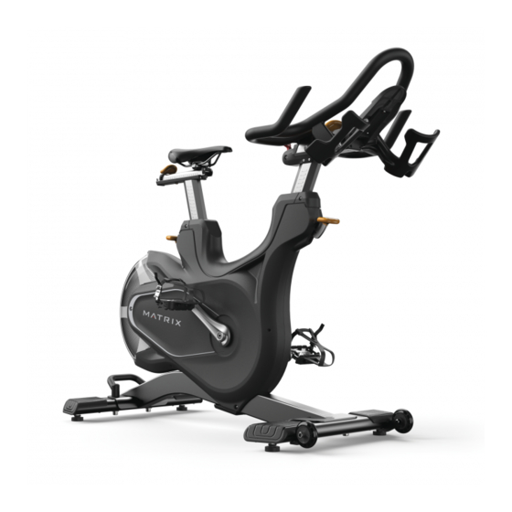
CHAPTER 7: SPECIFICATIONS AND ASSEMBLY GUIDE 7.3 ASSEMBLY INSTRUCTIONS HANDLEBARS TENSION CONTROL & EMERGENCY BRAKE LEVER DEVICE HOLDER SADDLE (CXM has console) HORIZONTAL SADDLE WATER BOTTLE HOLDER ADJUSTMENT LEVER HORIZONTAL HANDLEBAR SADDLE HEIGHT ADJUSTMENT LEVER ADJUSTMENT LEVER HANDLEBAR HEIGHT MAIN FRAME ADJUSTMENT LEVER SERVICE PANEL CRANK... - Page 27 CHAPTER 7: SPECIFICATIONS AND ASSEMBLY GUIDE 7.3 ASSEMBLY INSTRUCTIONS - CONTINUED STEP 1 Red Hardware Pack Description Bolt (M12x25L) Flat Washer Bolt (M12x70L) Torque Value 78 Nm / 58 ft-lb 78 Nm / 58 ft-lb...
- Page 28 CHAPTER 7: SPECIFICATIONS AND ASSEMBLY GUIDE 7.3 ASSEMBLY INSTRUCTIONS - CONTINUED STEP 2 Black (CX) / Yellow (CXM) Hardware Pack Description Stopper Screw (M8x20L) Slide handlebars onto frame before Screw (M4x6L) attaching (D), (E) and then (F) Torque Value 20 Nm / 14 ft-lb This part is for CXM only CXM only: Push to lock...
- Page 29 CHAPTER 7: SPECIFICATIONS AND ASSEMBLY GUIDE 7.3 ASSEMBLY INSTRUCTIONS - CONTINUED STEP 3 Pre-installed Hardware Description G Bolt (M6x50L) Torque Value 100 Nm / 74 ft-lb LEFT PEDAL...
-
Page 30: Chapter 8: Document Update History
CHAPTER 8: DOCUMENT UPDATE HISTORY 8.1 DOCUMENT UPDATE HISTORY Version Date Change Description 2018/2/8 Service manual released. - Page 31 NOTES...
- Page 32 M AT R I X F I T N E S S S Y S T E M S C O R P. 1 6 1 0 L A N D M A R K D R I V E C O T TA G E G R O V E W I 5 3 5 2 7 U S A T O L L F R E E 866.693.
Need help?
Do you have a question about the CXC FC20 and is the answer not in the manual?
Questions and answers