Table of Contents
Advertisement
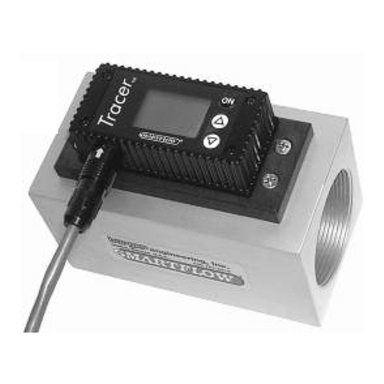
Tracer
Electronic Switching
®
Flowmeter
with FCI
Operating Instructions (Ver 5.1)
General
The Tracer Electronic Switching Flowmeter provides:
0 to 5V or 0 to 10V Selectable Flow Output
0 to 5V or 0 to 10V Selectable Temperature Output
1A, 30VAC/42VDC Programmable Switch for high
or low temperature and/or flow
Fluid Flow Rate Display in gallons per minute
(gpm) or liters per minute (lpm)
Fluid Temperature Display (°F or °C)
BTU's per Minute Display
Fluid Characteristic Indication (Turbulent Flow or
"TFLOW" on display)
BTU Basics
To obtain the most accurate BTU calculation, use the Tracer
to measure the supply side water temperature (in °F) before
installing the Tracer in a cooling water return line.
BTU's per minute calculation is based on the increase in water
temperature multiplied by the flow rate. The Tracer Electronic
Flowmeter calculates this information based on supply side
temperature entered manually. Due to inherent differences in most
thermometers, the most accurate BTU calculation will result from
using the same thermometer (inside the Tracer) to measure supply
and return line temperatures. Record the supply side temperature and
enter it using the "Set BTU/m Input Temperature" instructions on
page 3.
Turbulent Flow
"TFLOW" notification appears on the display when Turbulent Flow
is likely inside the cooling circuit of the selected size.
Turbulent flow is the mixing and swirling of water inside a cooling
line that provides optimum heat transfer. Water flow rate greater than
the point of Turbulent Flow does not provide a proportional benefit.
Turbulent flow tracking allows technicians to apply mathematical
cooling principles to all machines in a water system. Visit the
Technical Documents section of www.smartflow-usa.com for a
detailed discussion of Turbulent Flow.
Input the percentage of glycol in cooling water (0%, 10%, 20% or
30%) for accurate Turbulent Flow Indication. See Setup Mode option
on page 5. Antifreeze compounds of ethylene or propylene glycol are
sometimes added to cooling waer. Glycol compounds have
substantially higher viscosity than water. As a result, higher flow
rates are required to reach Turbulent Flow when glycol is used.
151 Memorial Drive, Unit H - Shrewsbury, MA 01545 - Phone: (888) 792-2223 - sales@plastixs.com - www.plastixs.com
Form #146 (02.16)
(Fluid Characteristic Indication)
U.S. Patent No.
7,729,869
pplication
Liquid running through the Tracer flowmeter
should be free of metal shavings. Loose
particles
can
interfere
components causing extra maintenance
requirements.
Specifications
Flow
Size [NPT(F)]
Range (gpm)
3/8"
0.5 to 8
3/4"
2.0 to 20
1"
3.0 to 30
1-1/2"
6.5 to 60
2"
10.0 to 110
Accuracy ....................±5% of Full Range
Repeatability ..............±3% of Full Range
Environment
Tracer construction is water resistant, but the
electronics housing is not submersible.
Temperature
Operating Range............32 to 180°F (0 to 82°C)
Accuracy........................±2% of Display Value
Repeatability..................±1% of Display Value
Component Materials
Body (3/8" model).........Nickel-Plated Brass
Body (3/4" thru 2")........Anodized Aluminum
Stainless Steel (optional)
Back Cover(3/8" only) ..Polysulfone
Impeller..........................Nylon 6/12
Magnet...........................Neodymium
Shaft...............................18-8 Stainless Steel
Electronics Cover ..........Nylon 6/6
Cable..............................9-Conductor, 24AWG
Operating
Internal Relay ................SPDT 1A, 30VAC/42VDC
Power Required .............8 to 28VDC
Maximum Pressure........100psi (7bar)
with
moving
Range (lpm)
0 to 30
8 to 76
11 to 114
25 to 228
38 to 418
Advertisement
Table of Contents

Related Manuals for Smartflow Tracer Series

Summary of Contents for Smartflow Tracer Series
-
Page 1: Specifications
Turbulent flow tracking allows technicians to apply mathematical Body (3/4" thru 2")..Anodized Aluminum cooling principles to all machines in a water system. Visit the Stainless Steel (optional) Technical Documents section of www.smartflow-usa.com for a Back Cover(3/8" only) ..Polysulfone detailed discussion of Turbulent Flow. Impeller......Nylon 6/12 Input the percentage of glycol in cooling water (0%, 10%, 20% or Magnet......Neodymium... -
Page 2: Installation Instructions
Installation Instructions For best performance, mount the Tracer flowmeter vertically with the flow entering the meter from the bottom. This provides full flow inside Wire Color Function the meter. We recommend a straight run of pipe equal to 10 pipe Black DC Ground diameters on the inlet side of the Tracer flowmeter and a straight run of... -
Page 3: Setup Mode
Setup Mode Setup Mode allows the user to select English or Metric units, input BTU/m inlet temperature, and set auto shut-off time. Δ and ∇ keys scroll through all options inside each display selection. Turn the display off before entering Setup Mode. Enter Setup Mode The display must be off to enter Setup Mode. - Page 4 Switch Set Points All switch set points are turned off when shipped from the factory. The switch actuates when sensed value(s) fall below low level set point(s) and/or sensed values rise above high level set point(s). The switch returns to normal state when the process fluid reaches programmed flow and/or temperature conditions.
- Page 5 Set Flow Rate Display Filter The Tracer flowmeter impeller changes speed as the water is swirling and mixing while passing through the meter. The filter program stabilizes the ∇ Δ display reading for the meter by averaging readings from the impeller. Filter can be turned ON or OFF. The recommended setting is ON.
-
Page 6: Analog Output Options
Analog Output Options Output Voltage for flow and temperature are set independently. 0 to 5V or 0 to 10V output is selectable for flow or temperature. The upper end of the effective flow range is also user-definable to give a more accurate flow and temperature reading over the voltage output range. -
Page 7: Calibration Mode
Calibration Mode Calibration Mode allows the user to adjust the calibration values for flow and temperature. Other functions include LCD self-test. There are eight functions or displays available through this mode. The ON button scrolls the menu through all functions until the user turns the display off. -
Page 8: Flow Calibration Procedure
Analog Output Calibration This calibration compensates the output for tolerances of electronic components. Analog Output Calibration sets the upper end of the temperature and flow output at exactly 10 Volts. Figure 25 Flow (See Figure 25): Connect the Orange wire to the + side of a voltmeter and the Black wire to ground connection. -
Page 9: Temperature Calibration Procedure
Flow Calibration Procedure (continued) Before you begin: Purge all the air from the system by running liquid through the test apparatus. For best results, take readings as close to full range as possible (at least 5 gpm for the 3/8"NPT, etc.). 1. -
Page 10: Maintenance Instructions
Fax: 816-878-6683 Freon TA www.smartflow-usa.com Limited Warranty Seller warrants that this product supplied will conform to the description herein stated and that the product will be of standard quality. This is the sole warranty made by Seller with respect to this product. Seller expressly disclaims any other express or implied warranties, including, but not limited to, the implied warranty of merchantability and the implied warranty of fitness for a particular purpose.
Need help?
Do you have a question about the Tracer Series and is the answer not in the manual?
Questions and answers