
Related Manuals for Honeywell 8712009


Summary of Contents for Honeywell 8712009
- Page 1 ENGLISH Installation & Operation Guide Digital Deadbolt Models 8712009, 8712109, 8712309, 8712409 Read this manual carefully before installing and operating! Page 1...
-
Page 2: Table Of Contents
Index INSTALLATION INSTRUCTIONS Package Contents / Tools Required.............Page 1 Prepare Door and Jamb.................Page 2 Adjusting Deadbolt Latch Set...............Page 3 Installing Deadbolt Latch Set................Page 4 Preparing Interior Assembly.................Page 5 Installing Exterior Assembly................Page 6 Installing Interior Assembly................Page 7-8 OPERATION INSTRUCTIONS Exterior Assembly Overview.................Page 9 Locking and Unlocking / Changing Programming Code / Adding User Codes..................Page 10 Deleting User Codes / Automatic Lock Function /... -
Page 3: Installation Instructions
INSTALLATION INSTRUCTIONS PACKAGE CONTENTS Entry keys (2 ea.) Deadbolt Latch Set (Adjustable) 2-3/8” (60mm) to 2-3/4” (70mm) Mounting Plate Interior Assembly Deadbolt Strike Plate Exterior Assembly 5/16” (8mm) Screws - 2 ea. 7/8” (22mm) Screws - 2 ea. 3/4” (19mm) Screws - 5 ea. 1”... -
Page 4: Prepare Door And Jamb
PREPARE DOOR AND JAMB NOTE: For installation on doors with pre-drilled holes skip to page 4. 1. TEMPLATE a. Cut out template printed on page 15 of this Manual (Figure 1a). b. Fold template and place on door 36” (915mm) from the ground as marked (Figure 1b). -
Page 5: Adjusting Deadbolt Latch Set
ADJUSTABLE DEADBOLT LATCH SET NOTE: Deadbolt Latch Set is shipped with the backset set at 2-3/8” (60mm) Measure the backset (backset is distance between edge of the door and the center of Lock). 1. TO CONVERT FROM 2-3/8” (60mm) BACKSET TO 2-3/4” (70mm) BACKSET a. -
Page 6: Installing Deadbolt Latch Set
INSTALLING DEADBOLT LATCH SET 3. INSTALLING THE DEADBOLT LATCH SET (need phillips head screwdriver) a. Insert Deadbolt Latch Set into door edge hole with the word “UP” and the arrow on the extension plate facing UP. Cross shaped spindle connector will be at the bottom of the Deadbolt Latch Set (Figure 3a). -
Page 7: Preparing Interior Assembly
PREPARING THE INTERIOR ASSEMBLY 5. UNPACK THE INTERIOR ASSEMBLY a. Remove the battery cover by sliding the cover upward. b. Locate the screws holding the Mounting Plate to the Interior Assembly. Remove the screws to release the Mounting Plate from the Interior Assembly. 6. -
Page 8: Installing Exterior Assembly
INSTALLING EXTERIOR ASSEMBLY 8. INSTALLING THE EXTERIOR ASSEMBLY Work with the Door Open for easy access. a. Unpack the Exterior Assembly. Use care to not scratch the green circuit board during handling and installation. b. Check that the Rubber Gasket is properly seated on the Exterior Assembly (Figure 8a-b). -
Page 9: Installing Interior Assembly
INSTALLING INTERIOR ASSEMBLY 11. ATTACH THE CONTROL WIRE TO THE INTERIOR ASSEMBLY a. Use care to attach the Control Wire male plug to the Interior Assembly female socket connector (Figure 11a). b. Do not force the Control Wire male plug into the Interior Assembly female socket connector (Figure 11b). - Page 10 Insert 4 AA high quality Alkaline batteries into the Battery Compartment in the direction noted +/- on the Compartment. The Lock will beep 2 times, the keypad will illuminate blue, and the Honeywell button will flash green twice to signify that it has received power (Figure 13a).
-
Page 11: Operation Instructions
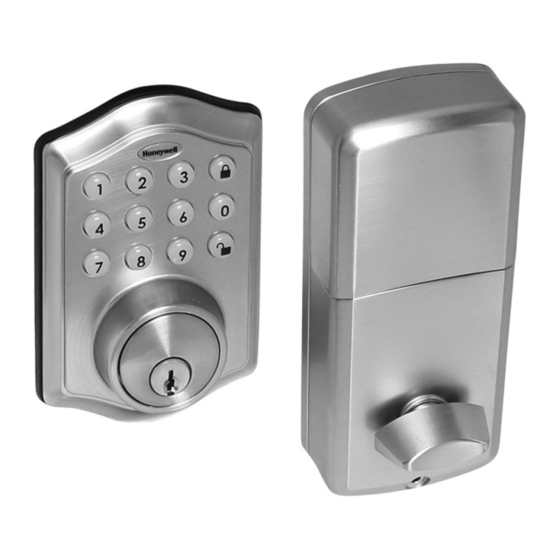
OPERATION INSTRUCTIONS EXTERIOR ASSEMBLY OVERVIEW Green • Indicates Successful Programming Step Indicator light • Indicates Unlocking is Successful • Indicates Failed Programming Step • Indicates Locking is Successful Lock button Lock - Used to lock door Clear - Used to clear wrong keypad entries Unlock button Unlock - Used to unlock door Programming - Used in programming steps... -
Page 12: Adding User Codes
LOCKING AND UNLOCKING TO UNLOCK THE LOCK Using Keypad: Enter a valid User Code (default code is 1234) and press and hear 1 beep and lights green. TO LOCK THE LOCK Using Keypad: Press and then hear 2 beeps and lights red. CHANGING PROGRAMMING CODE CHANGE CURRENT OR PRESET PROGRAMING CODE Factory default Programming Code... -
Page 13: Temporarily Disable Auto Lock
DELETING USER CODES DELETE ONE EXISTING OR PRESET USER CODE The unit comes with a factory User ID = 01 for User Code = 1234. IMPORTANT: To delete 1 User Code , the lock must have more than 1 User Code in its database. -
Page 14: Vacation Mode / Secure Lock-Out Period / Sound On And Off Restore Factory Settings / Low Battery Warning
VACATION MODE With Vacation Mode enabled, the system enters into low-power comsumption mode. During this mode, all buttons and functions including the remote controll will be invalid until they are re-enabled (see steps below). ENABLE: Hear 1 beep and Light Indicator illuminates green then lock door DISABLE: To disable the Vacation Mode, you must press and hold for more than 3 seconds,... -
Page 15: Consumer Friendly Message Guide / Programming Record
CONSUMER FRIENDLY MESSAGE GUIDE Unlock / Valid programming: 1 long beep and LED illuminates green Lock: 2 short beeps and LED illuminates red Invalid Programming: 2 short beeps and LED flashes red twice Low Voltage: Beeps for 5 seconds (7/9 times depends on operation is unlock/lock) Super Low Voltage: 4 short beeps and LED flashes red four times 4 Incorrect code entry attempts:... -
Page 16: Installation Trouble Shooting
INSTALLATION TROUBLE SHOOTING Issue Solution Latch Working Direction switch is set to incorrect setting. Backwards- Remove the Interior Assembly and move the switch to the opposite Lock unlocks when direction. lock button is pushed • Check that your switch is set in the correct position Left or Right or locks when unlock Handed door. - Page 17 Page 15...
-
Page 18: Template
BACK OF TEMPLATE Page 16... -
Page 19: Consumer Assistance
CONSUMER ASSISTANCE EMAIL: LHLPCustomerService@LHLPinc.com WEBSITE: www.honeywellsafes.com ADDRESS: Consumer Assistance Dept. LH Licensed Products, Inc., 860 East Sandhill Avenue Carson, CA 90746 USA TELEPHONE: US/Canada 1-877-354-5457 (Toll Free) Mexico 01-800-288-2872 After English voice recording stops you must then enter 800- 860-1677 to complete your call. (Toll Free) Australia 0011-800-5325-7000 (Toll Free) Germany/New Zealand 00-800-5325-7000 (Toll Free) Other Countries XX*-310-323-5722 (Toll Charges Apply) - Page 20 Manufactured by: LH Licensed Products, Inc. 860 East Sandhill Avenue Carson, CA 90746 The Honeywell Trademark is used under license from Honeywell International Inc. Honeywell International Inc. makes no representations or warranties with respect to this product. MEEDBKP-RE20160620 www.honeywellsafes.com Page 18...
Need help?
Do you have a question about the 8712009 and is the answer not in the manual?
Questions and answers
reset programming code
To reset the programming code for the Honeywell digital deadbolt model 8712009, follow these steps:
1. The factory default programming code (PC) is 123456.
2. Enter the current or preset programming code.
3. Follow the specified sequence to change the programming code.
4. Complete all programming steps within 5 seconds.
5. Use the key to clear entries if a wrong button is pressed.
For security, change the programming code as soon as possible after installation.
This answer is automatically generated
Changed batteries in my Tru-Bolt 8712009 the key pad lights when I put the batteries in then goes off when I push the numbers on the key pad nothing happens and I don't know what it doesn't work now its been installed for about 2 years
reset to factory specs