
Subscribe to Our Youtube Channel
Related Manuals for SWR Envea M-Sens 2


Summary of Contents for SWR Envea M-Sens 2
- Page 1 M-Sens 2 M-Sens 2 Online moisture measurement Online moisture measurement Online moisture measurement for solids for solids...
-
Page 2: Table Of Contents
CONTENTS Page System overview ..........3 Function . -
Page 3: System Overview
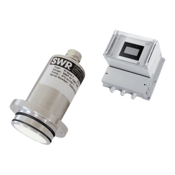
1. System overview A complete M-Sens 2 unit consists of the following components: Flange (mounting in screw, hopper) • 1 to 3 sensors with 2 m connecting cable • Transmitter MME 300 for 2 to 3 sensors in a fi eld housing •... -
Page 4: Function
2. Function The M-Sens 2 sensor functionality is based on precise high-frequency measurement and direct digitalization of measured values, where from results a high resolution. As the material surface and capillary moisture influences strongly its specific conductive capacity, the moisture can be measured exactly by a constant averaged bulk density. -
Page 5: Safety
If a damage is found, it is to repaired before further operation of the instruments. Technical progress ENVEA - SWR engineering reserves the right to adapt technical data to the technical progress without • particular advance notice. If you have any questions, ENVEA - SWR engineering will be pleased to... -
Page 6: Mounting And Installation
4. Montage and installation 4.1 Delivery parts Transmitter in the field housing • Sensor • Operating instructions • C1-box (optional) • Welding flange • 4.2 Auxiliary Screw driver 2.5 mm • Allen key 5 mm • 4.3 Mounting of the sensor M-Sens 2 is designed for continuous moisture measurement. - Page 7 APPLICATIONS - PRACTICAL EXAMPLES Installation in a screw • The installation of a moisture sensor in screw feeders proved to be very advantageous, since the material passes by the sensor window in even intervals and with relatively constant bulk density. 13,1 Moisture Screw feeder...
- Page 8 Installation in a bin • Another installation alternative is to mount a sensor at a bins outlet. Due to constant bulk density in case of a filled bin, the sensor finds an almost unchanging measuring field for monitoring the residual moisture.
- Page 9 Moisture measurement in a mixer • M-Sens 2 can be installed, even later on, in all types of mixers. The measuring values logging is done by within the moving material during the mixer procedure. With the measured moisture value of the material in the dryer process parameters like detention time and dosage quantity can be controlled.
-
Page 10: Mounting Of The Transmitter
4.4 Mounting of the transmitter The whole electronic equipment can be installed at a maximum distance of 300 m from the sensor. The housing is prepared for wall mounting. Fig. 9: Field housing for the transmitter Sensor 1 Transmitter Cable gland M 16 x 1,5 Fig. -
Page 11: Use In Ex Hazard Array
4.5 Use in Ex hazard area Marking DustEx: II 1D Ex maD iaD 20 T120 °C - Group of equipment 2 - Equipment category: 1 - Zone 20 - For combustible mixtures from air and inflammable type of dust - Allowable process temperature 0 ... 80 °C - Maximum surface temperature 135 °C with Ta = 60 °C Marking GasEx: II 1G Ex ma ia CII T4... -
Page 12: Electrical Connection
5. Electrical connection Fig. 12: Electrical connection Transmitter Terminal no. Connection Connection of the power supply L / +24 V Input power supply 230 V / 50 Hz, 110 V / 60 Hz (optional 24 V DC) N / 0 V Input power supply 230 V / 50 Hz, 110 V / 60 Hz (optional 24 V DC) Protected earth Sensor connection... -
Page 13: Commissioning
Correct installation of the sensor in respect to the wall thickness. • In case of negative results in spite of consideration of the points as stated above, please contact SWR. Commissioning of the M-Sens 2 After the delivery the sensor is not calibrated to the product(s), so each calibration and parameterization has to be executed during the commissioning. - Page 14 Digital inputs Under menu point 3 you define the digital inputs. Every digital input can be used to start and stop the moisture measurement. Alternated the digital inputs can be used for change of 4 different products. Basic points The measurement can be checked for linearity by means of varying moisture values.
-
Page 15: Menu Structure Of M-Sens 2
In the following there is the menu structure: 7. Menu Structure of M-Sens 2 Products Products 1 to 4 Measurement range 1.1.1 Product name Choice of material (8 char) 1.1.2 Unity Choice unit text, e. g. % H O / % TS 1.1.3 Decimal place Decimal place position... - Page 16 1.4.6 Calibration point 1 Measurement range start and end 1.4.7 Measured value Record of input value 1.4.8 Calibration point 2 ... (depends on the number of the 1.4.9 Calibration calibration points) 1.4.10 Calibration point N Measurement range init and end 1.4.11 Measured value Record of input value...
-
Page 17: Menu Parameters
8. Menu parameters 1.1 Measurement range 1.1.1 Product name Measurement range £ Select the name of medium and location Product name ¤ (max. 8 char). Material £ ¤ Choose the characters with ¡ ¢ the each corresponding position (1 ... 8) with ¢... - Page 18 1.1.6 Filter value Measurement range Filter Setting of the damping time between (range between 0.1 ... 999.9 s). With you set the value to 0.0. With the numbers you input the beginning value and with the input is accepted and you quit the menu level.
- Page 19 1.2.4 Alarm hysteresis Alarm 1 Choose the value for clearing the alarm. Hysteresis Range between 0.1 ... 99.9 % in the defined 1.0 % measurement range. With you set the value to 0.0. With the numbers you input the beginning value and with the input is accepted and you quit the menu level.
- Page 20 Only necessary in case of disturbing nonlinearity (see chart). The base points of the ideal characteristic curve are entered and calibrated down to the actual characteristic curve. If the following adjustment is done, the signal output will be linear. 1.4.3 Calibration factor Calibration for sensor 1 Factor 1...
- Page 21 1.4.8 Calibration point 2 Choose the measured value in physical unities - beginning and end of measurement range. 1.4.9 Measured value 2 Input value is collected and assigned to the shown measured value. 1.4.10 Calibration point N . . . depends on the number of calibration points 1.4.11 Measured value Input value is collected and assigned to the shown measured value.
- Page 22 5.4 MAX limit Analogue output MAX limit Choose the minimal output value in the range of 0 ... 22 mA (Standard 20 mA). 20.0 With you set the value to 0.0. With the numbers you input the beginning value and with the input is accepted and you quit the menu level.
- Page 23 Digital inputs 6. Digital inputs £ It is only necessary for stopping and starting 6.1 Digital input ¤ the measurement via an external control line 6.2 Digital input (for wiring see 9) £ ¤ With you make a choice according to the display. With you quit the menu point without any change and with the input is accepted and you...
- Page 24 System 7. System £ Setting of the ModBus interface parameters 7.1 Baud rate 960 9600 ¤ when connecting to the system bus. 7.2 Address 7.3 Contrast 7.4 Language £ ¤ With you make a choice according to the display. With you quit the menu point without any change and with the input is accepted and you arrive 1 menu point lower to make your settings.
-
Page 25: Wiring Example
7.6 Display temperature System £ Determine if the temperature is shown in the Temperature display ¤ display - the values are on and off. The temperature of the sensor is not available via current output. This value do not represents the temperature of the product. -
Page 26: Warranty
Replaced parts turn into the property of ENVEA - SWR engineering. If desired by the costumer that the parts should be repaired or replaced in its factory, then the costumer has to take over the costs for the ENVEA - SWR engineering-service staff. -
Page 27: Technical Data
Digital inputs 2 inputs for active external control signals Data protection Flash SWR engineering Messtechnik GmbH Gutedelstraße 31 · 79418 Schliengen (Germany) Fon +49 7635 827248-0 · Fax +49 7635 827248-48 · www.swr-engineering.com PART OF THE ENVEA GROUP EN 07/06/2018...
Need help?
Do you have a question about the Envea M-Sens 2 and is the answer not in the manual?
Questions and answers