Table of Contents
Advertisement
Quick Links
Service
Manual
CLASS D MONO AMPLIFIER
GM-D510M
GM-D510M
GM-D510M
For details, refer to "Important symbols for good services".
PIONEER CORPORATION
PIONEER ELECTRONICS (USA) INC.
PIONEER EUROPE NV
Haven 1087 Keetberglaan 1, 9120 Melsele, Belgium
PIONEER ELECTRONICS ASIACENTRE PTE.LTD. 253 Alexandra Road, #04-01, Singapore 159936
C PIONEER CORPORATION 2004
GM-D510M/X1R/EW
/X1R/UC, /X1H/UC
/X1R/ES, /X1H/ES
4-1, Meguro 1-Chome, Meguro-ku, Tokyo 153-8654, Japan
P.O.Box 1760, Long Beach, CA 90801-1760 U.S.A.
ORDER NO.
CRT3223
/X1R/EW, /X1H/EW
K-ZZB. FEB. 2004 Printed in Japan
Advertisement
Table of Contents

Related Manuals for Pioneer GM-D510M/X1R/EW


Summary of Contents for Pioneer GM-D510M/X1R/EW
- Page 1 PIONEER ELECTRONICS (USA) INC. P.O.Box 1760, Long Beach, CA 90801-1760 U.S.A. PIONEER EUROPE NV Haven 1087 Keetberglaan 1, 9120 Melsele, Belgium PIONEER ELECTRONICS ASIACENTRE PTE.LTD. 253 Alexandra Road, #04-01, Singapore 159936 C PIONEER CORPORATION 2004 K-ZZB. FEB. 2004 Printed in Japan...
-
Page 2: Safety Information
By following the instructions in this manual, be sure to apply the prescribed grease or glue to proper portions by the appropriate amount.For replacement parts or tools, the prescribed ones should be used. GM-D510M/X1R/EW... -
Page 3: Table Of Contents
• Specifications and the design are subject to possible modification without notice due to improvements. *Average current drawn • The average current drawn is nearly the maximum current drawn by this unit when an audio signal is input. Use this value when working out total current drawn by multiple power ampli- fiers. GM-D510M/X1R/EW... -
Page 4: Exploded Views And Parts List
2. EXPLODED VIEWS AND PARTS LIST 2.1 PACKING GM-D510M/X1R/EW... -
Page 5: Gm-D510M/X1R/Ew
- For the applying amount of lubricants or glue, follow the instructions in this manual. ( In the case of no amount instructions, apply as you think it appropriate.) - PACKING SECTION PARTS LIST Part No. GM-D510M/X1R/EW GM-D510M/X1R/UC GM-D510M/X1R/ES Mark No. Description GM-D510M/X1H/EW... -
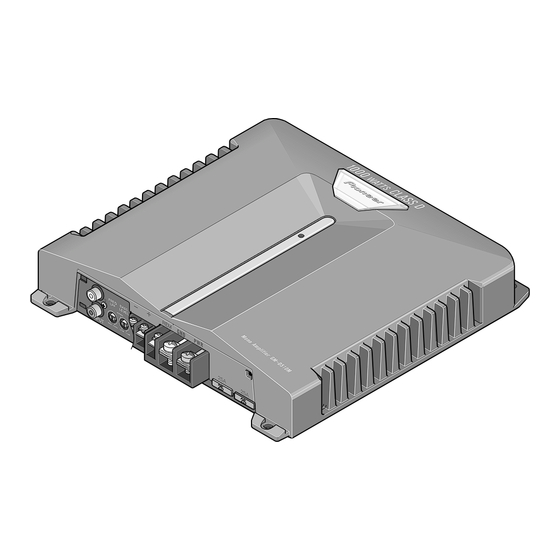
Page 6: Exterior
2.2 EXTERIOR GM-D510M/X1R/EW... -
Page 7: Gm-D510M/X1R/Ew
2SB1566 41 Thermistor(TH601,602) HCX0002 42 Diode(D610) FML22R 43 Diode(D611) FML22S 44 FET(Q610-615) IRF2807 45 FET(Q401,402,405,406) SPP18P06P 46 FET(Q403,404,407,408) SPP21N10 47 Volume(VR101) HCS0002 48 Variable Resistor(VR201) CSS1265 49 Spacer HNM0006 50 ••••• Not used 51 LED(D910) DB3804X 52 Screw ISS30P060FTC GM-D510M/X1R/EW... -
Page 8: Schematic Diagram
Note: When ordering service parts, be sure to refer to " EXPLODED VIEWS AND PARTS LIST" or "ELECTRICAL PARTS LIST". Large size SCH diagram AMP PCB Guide page Detailed page AMP UNIT Consists of AMP PCB CONNECTOR PCB Switch GM-D510M/X1R/EW... -
Page 9: Gm-D510M/X1R/Ew
The > mark found on some component parts indicates ← 0.022 R022 Symbol indicates a capacitor. the importance of the safety factor of the part. No differentiation is made between chip capacitors and Therefore, when replacing, be sure to use parts of discrete capacitors. identical designation. GM-D510M/X1R/EW... -
Page 10: Gm-D510M/X1R/Ew
GM-D510M/X1R/EW... -
Page 11: Gm-D510M/X1R/Ew
A-b B GM-D510M/X1R/EW... -
Page 12: Gm-D510M/X1R/Ew
GM-D510M/X1R/EW... -
Page 13: Gm-D510M/X1R/Ew
A-b B GM-D510M/X1R/EW... -
Page 14: Pcb Connection Diagram
For further information for respective destinations, be sure to check with the schematic dia- gram. 2.Viewpoint of PCB diagrams Capacitor Connector SIDE A SIDE B P.C.Board Chip Part FRONT CN703 CN702 CN701 GM-D510M/X1R/EW... -
Page 15: Gm-D510M/X1R/Ew
SIDE A GM-D510M/X1R/EW... -
Page 16: Gm-D510M/X1R/Ew
AMP PCB GM-D510M/X1R/EW... - Page 17 SIDE B GM-D510M/X1R/EW...
-
Page 18: Connector Pcb
4.2 CONNECTOR PCB SIDE B CONNECTOR PCB SIDE A CONNECTOR PCB CN601 CN601 CN601 GM-D510M/X1R/EW... -
Page 19: Electrical Parts List
HCX0003 Thermistor HCX0003 IRF2807 Switch(BFC)(EW,ES) HSH-156 IRF2807 Volume 20kΩ(E) HCS0002 Transistor KSA1175 Variable Resistor 10kΩ(A) CCS1265 Transistor KSA1175 Transistor KCS2785 Semi-fixed 100kΩ(OB) RH063MC15R RESISTORS Transistor KCS2785 Transistor 2SD2395 Transistor 2SB1566 RS1/16S432J Transistor KSR2102 RS1/16S432J Transistor DTC114TK RS1/16S432J RS1/16S432J RS1/16S432J GM-D510M/X1R/EW... - Page 20 RN1/16SE6201D RD1/4PU223J RN1/16SE6201D RS1/16S124J 24Ω HCN0006 RS1/16S472J 6.80Ω HCN0002 RS1/16S472J RS1/16S103J RS1/16S123J RS1/16S103J RS1/16S182J RS1/16S103J RS1/16S223J RS1/16S103J RS1/16S182J RS1/16S101J RS1/16S153J 0.01Ω HCN0003 RS1/2PMF100J 0.01Ω HCN0003 RS1/2PMF100J 0.01Ω HCN0003 RS1/16S272J 0.01Ω HCN0003 RS1/16S222J RS1/2PMF102J RS1/16S471J RS1/2PMF102J RS1/16S471J 24Ω HCN0006 RS1/16S223J GM-D510M/X1R/EW...
- Page 21 CQMA472J50 CKSRYB183K50 CQMA102J50 3900µF/16V HCH0018 CQMA471J100 3900µF/16V HCH0018 4.7µF/63V HCH0017 4.7µF/63V HCH0017 3900µF/16V HCH0018 1.0µF/100V HCH0019 CFTNA154J50 1.0µF/100V HCH0019 220µF/35V HCH0032 220µF/35V HCH0032 CFTNA104J50 CEATR10M50 CFTNA104J50 CFTNA474J63 CEATR10M50 CEANP4R7M63 CEAT470M50 CFTNA103J50 CEAT470M50 CFTNA103J50 CFTNA103J63 CFTNA103J50 CKSRYB103K50 CKSRYB103K50 CEAT1R0M50 CEAT1R0M50 GM-D510M/X1R/EW...
-
Page 22: Adjustment
3300µF/16V HCH0006 CFTNA103J50 CKSRYB103K50 CKSRYB103K50 CKSRYB103K50 CKSRYB103K50 CKSRYB103K50 CKSRYB103K50 CKSRYB103K50 CEAT2R2M50 CKCYB472K50 CKSRYB222K50 CKSRYB222K50 CKSRYB471K50 CKSRYB471K50 CEAT100M16 CEAT100M16 CQMA472J50 CQMA472J50 CCSRCH470J50 CCSRCH470J50 CCSRCH271J50 CCSRCH271J50 CKSRYB222K50 220µF/10V HCH0012 6. ADJUSTMENT There is no information to be shown in this chapter. GM-D510M/X1R/EW... -
Page 23: General Information
Removing the Case (Fig.1) Case Remove the screw. Remove the six screws and then remove the Case. Fig.1 Removing the Amp PCB (Fig.2) Remove the six screws. Remove the screw and then remove the Amp PCB. Amp PCB Fig.2 GM-D510M/X1R/EW... -
Page 24: Connector Function Description
7.1.2 CONNECTOR FUNCTION DESCRIPTION GM-D510M/X1R/EW... - Page 25 25 -Vs+VRefl -Vs+VRefr 60 CHANNEL LEFT CHANNEL RIGHT CHANNEL RIGHT CHANNEL LEFT LSD + HSD + HSD + LSD + 24 SNL1 SNR1 61 PROTECTIONS PROTECTIONS PROTECTIONS PROTECTIONS 23 SNL2 SNR2 62 22 GNLS GNRS 63 21 GNL GNR 64 GM-D510M/X1R/EW...
-
Page 26: Operations
(standard output of 500 mV), set to The power indicator lights when the NORMAL position. When using with an RCA equipped Pioneer car stereo with the power is switched on. max. output of 4 V or more, adjust level to match the car stereo output level.
Need help?
Do you have a question about the GM-D510M/X1R/EW and is the answer not in the manual?
Questions and answers